
Abstract
Laser polishing is widely employed to reduce the surface roughness of products with complex geometries. Traditional laser polishing techniques use a single high-power Gaussian beam to melt and smooth a thin layer of surface material. However, the reliance on high power lasers can present practical challenges such as minimizing surface evaporation or reducing overall cost. In this work, we combined two identical low-power laser beams with a spatial offset in between them to construct an elliptical beam. By changing the spatial offset, combined beams with different lengths along the major axis can be created. We observe over 20% improvement in line roughness reduction using this approach compared to a single Gaussian laser beam with the same total power. Additionally, both experiment and simulation results suggest such improvement is because this dual-laser set-up can create a longer molten pool compared to a single laser.
Export citation and abstract BibTeX RIS

Original content from this work may be used under the terms of the Creative Commons Attribution 3.0 license. Any further distribution of this work must maintain attribution to the author(s) and the title of the work, journal citation and DOI.
1. Introduction
Laser polishing is widely used to reduce the surface roughness of products with complex geometries, as those geometries are often challenging for conventional manual polishing methods [1–4]. In laser polishing, a thin layer of surface material is melted by laser heating. The melted material is then redistributed by surface tension and solidified to form a smoother surface [5]. Recently, Krishnan and Fang have reviewed various laser polishing techniques along with their advantages and disadvantages [6]. One of the major challenges identified in this review is the difficulty to optimize the laser energy density in the polishing process.
In conventional laser polishing with only one Gaussian-shaped laser beam, laser power, scan speed and beam diameter change the beam energy density and can subsequently affect the polishing results [7]. On one hand, a smaller beam with higher laser power can generate large energy density, which leads to localized high temperatures, evaporation of the surface material and steep temperature gradients inside the molten pool [8]. Strong thermo-capillary fluid flow can also occur with large temperature gradients and deteriorate the polishing outcome [9, 10]. On the other hand, defocusing the laser beam by a small focal offset to enlarge the beam diameter can decrease the peak intensity. Larger beam size sometimes improves polishing results but requires very high laser power, often above 100 W to ensure the energy density meets the melting threshold [11–14].
Because of the limitations of using a single Gaussian beam, several other methods have been explored to more precisely control the beam energy distribution in laser polishing. For example, Nüsser et al and Rosa et al tested laser intensity profiles other than Gaussian. Rosa et al used circular top-hat energy distribution [15] while Nüsser et al studied both top-hat circular and square distributions [16]. Additionally, Nüsser et al investigated the effect of adding a continuous-wave laser as a preheating source before a pulsed laser in the polishing process [17]. Recently, Zhou et al used a similar dual-laser set-up including a continuous-wave and a pulsed laser but changed both beams' intensity profiles to top-hat [18]. While some improvements were observed with these beam shaping techniques, high laser powers are still required for optimal polishing results.
Here, we report a method to shape the laser beam by combining two equal-power continuous-wave lasers. In contrast to the methods used by Nüsser et al and Zhou et al where one auxiliary beam is used only for preheating, both lasers in our system have enough power to melt surface material. The two beams are separated by a small spatial offset so that the superposition of the two beams generates an elliptical beam moving along its major axis. In the past, elliptical beam was modulated in other applications by using a cylindrical lens [19] or by an anamorphic prism pair [20]. However, tilting the laser beam might become physically challenging to construct a very long elliptical spot. Furthermore, we use this method because this dual-laser set-up expands our parameter space.
With our set-up, we expect improved polishing performance with this geometry compared to the single beam as the combined beam creates a longer molten pool and smaller temperature gradient. At the same time, because the combined beam distributes more energy along the scanning direction, such configuration could reduce the minimum required laser power for desired polishing results. Experiments with a single Gaussian beam at various focus offset distances are performed to serve as a reference for the dual-laser experiments.
2. Experimental setup
2.1. Dual-laser set-up
Figure 1 shows the set-up in the dual-laser experiments. Two 1070 nm wavelength lasers with Gaussian-shaped beams operated in continuous-wave mode are used as the laser sources in this experiment. A focusing telescope is placed after each laser output to reduce the laser beam diameter. The shrunk beams then enter the 3-D scanning systems including beam expanders, 2D scanners and F-θ lenses. Each of the scanning system has a scan field of 178 × 178 mm2. By putting two scanners side-by-side, an overlapping scan area of 20 × 178 mm2 is created. Both lasers and scanners are controlled by control cards installed in a PC. A pulse generator is used to control the firing time delay between two lasers and thus create a small spatial offset between the two laser beams. A high-speed camera captures the image at 10 000 fps with 7 µm exposure time.
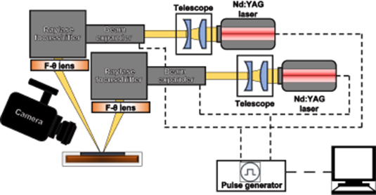
Figure 1. The dual-laser experimental set-up.
Download figure:
Standard image High-resolution image2.2. Polishing method
The initial rough surface is created by laser melting a SS316 sheet. Surface roughness is measured using a confocal microscope with a 50 × objective at vertical and horizontal resolution of 60 nm and 250 nm respectively. One set of height profiles collected from confocal microscope is shown in figure 2. Ra of the initial rough surface is around 5 µm and Rz is around 20 µm. In addition, figure 3 shows the SEM images of the line polishing results. Figure 3(a) shows the morphology of the molten track from the top angle while figure 3(b) is from a tilted angle for a clearer view on the polishing performance.

Figure 2. Confocal images of the polished line and height profiles.
Download figure:
Standard image High-resolution image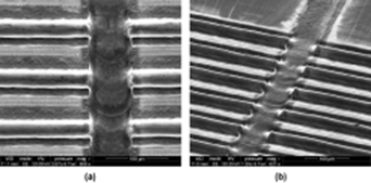
Figure 3. SEM images of the line polishing result. (a) is from the top angle and (b) is from a tilted angle.
Download figure:
Standard image High-resolution imageIn the single-laser polishing experiment, the beam size is controlled by defocusing the beam away from the focal plane. The relationship between beam flux and beam diameter is described in equation (1), where P is the beam power and D is the beam diameter (measured at 1/e2 of the peak intensity, as shown at the left plot in figure 4). For single beam laser polishing, energy density is calculated using equation (2) where v is the scan speed. Table 1 lists the parameters in the single laser polishing experiment.
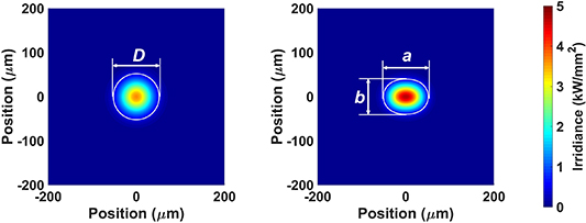
Figure 4. Schematic beam irradiance from the single laser set-up (left, 15 W power with 3.5 mm focal offset distance) and dual laser set-up (right, 2 × 7.5 W power, 30 mm s−1 speed with 1 ms time delay). White contour line represents 1/e2 of the peak power. Both beams have lengths of 100 µm.
Download figure:
Standard image High-resolution imageTable 1. Single laser polishing experimental design.
| Power (W) | Scan speed (mm s−1) | Beam diameter (µm) | Beam flux (kW mm−2) | Energy density (J mm−2) |
|---|---|---|---|---|
| 11 | 30 | 78–93 | 2.30–1.68 | 4.70–4.01 |
| 12 | 30 | 78–116 | 2.51–1.14 | 5.13–3.45 |
| 15 | 30 | 78–138 | 3.14–1.00 | 6.41–3.61 |
| 18 | 30 | 78–146 | 3.77–1.07 | 7.69–4.10 |
| 22 | 30 | 78–180 | 4.61–0.879 | 9.40–4.08 |
| 40 | 30 | 78–197 | 8.38–1.32 | 17.1–6.77 |
The experimental parameters of dual-laser set-up can be found in table 2. In the dual-laser set-up, both laser beams are focused to a diameter of 78 µm. Each laser contains half of the power reported in table 2 as table 2 reports the combined laser power. Both lasers move in the same direction at the same speed. A pulse generator introduced a small time offset (⩽5 ms) between the firing of these two lasers and thus created a spatial offset (⩽125 µm) between the two laser beams. An elliptical beam is then constructed from the superposition of these two laser beams.
Table 2. Dual laser polishing experimental design.
| Power | Scan speed | Time delay | Spatial offset | Beam length | Beam flux | Energy density |
|---|---|---|---|---|---|---|
| (W) | (ms) | (mm s−1) | (µm) | (µm) | (kW mm−2) | (J mm−2) |
| 12 | 30 | 0–1.95 | 2–58.2 | 78–136 | 2.52–1.44 | 5.13 |
| 15 | 30 | 0–2.05 | 0–61.5 | 78–140 | 3.14–1.75 | 6.41 |
| 22 | 20 | 0–2.38 | 0–47.6 | 78–125 | 4.61–2.88 | 14.1 |
| 22 | 25 | 0–2.00 | 0–50.0 | 78–128 | 4.61–2.82 | 11.3 |
| 22 | 30 | 0–2.25 | 0–67.5 | 78–146 | 4.61–2.47 | 9.40 |
| 22 | 40 | 0–1.00 | 0–40.0 | 78–115 | 4.61–3.13 | 7.05 |
| 30 | 25 | 0–5.00 | 0–125.0 | 78–203 | 6.28–2.41 | 15.4 |
| 30 | 30 | 0–1.75 | 0–52.5 | 78–130 | 6.28–3.77 | 12.8 |
| 30 | 40 | 0–1.05 | 0–42.0 | 78–118 | 6.28–4.17 | 9.62 |
| 36 | 30 | 0–2.25 | 0–67.5 | 78–146 | 7.54–4.04 | 15.4 |
| 36 | 40 | 0–1.00 | 0–40.0 | 78–115 | 7.54–5.12 | 11.5 |
The combined beam is quantified by the length a of its major axis and length b of its minor axis (both measured at 1/e2 of the peak intensity, as shown at the right figure in the figure 4). The length a changes with different spatial offsets while the length b remains at 78 µm. Again, with beam power P and scan speed v, beam flux and energy density are calculated using equations (3) and (4)
It is noted that as the length b of the constructed beam is not affected by the change in the spatial offset, energy density remains the same for beams with the same laser power and scan speed. Therefore, we focus more on the influence of beam flux in the following analysis and discussion.
After each polishing experiment, the line profile of the polished region is measured with the confocal microscope, as shown in figure 2. The roughness reductions reported are calculated as

where Ra i is the average roughness of the central line before polishing and Ra f is the average roughness of the central line after laser polishing.
2.3. Simulation methods
Simulation of the laser polishing experiment was conducted on COMSOL®5.4
Two modulus including heat transfer in fluids with phase change and laminar flow are coupled with nonisothermal flow Multiphysics in the model. Marangoni effect Multiphysics is also used to simulate the surface tension change with various temperature. Material properties including density, heat diffusivity and surface tension at different temperatures are obtained from previous literature [21, 22]. Viscosity of the solid phase is set at 15 Pa s while the liquid phase viscosity is set at 0.05 Pa s.
In the simulation, a 1 × 1 × 1.7 mm3 block with a symmetrical plane on one of the 1 × 1.7 mm2 planes is constructed, as shown in figure 5. Mesh with sizes smaller than 5 µm is only used in the laser-material interaction region to save computation time. The laser interaction is modeled with two Gaussian-shaped heat flux sources and a small spatial offset between the sources using the experimental parameters. The heat influx is deposited along the long axis defined by the upper surface and the symmetrical plane. In the laser interaction zone, Tetrahedral elements with a maximum elect size of 10 µm are used to resolve the pulse shape. All the planes have open boundary conditions except the symmetrical plane and the upper plane which has a surface-to-ambient radiation condition. A time-dependent study with a 10 ms time period and a 10 ns step is simulated to ensure that the stationary conditions are reached. The resulting temperature distributions are then collected from the simulation.

Figure 5. Building block in COMSOL simulation. Region with the smallest mesh is the laser-metal interaction area.
Download figure:
Standard image High-resolution image3. Results and discussion
3.1. Single laser polishing results
Figure 6 shows the roughness reduction of the single laser experiments. Figure 6(a) plots the roughness reduction with respect to the beam diameter at different laser powers. In all experiments the laser beam moves at a velocity of 30 mm s−1. When the laser power is small (e.g. 11 and 12 W), the highest roughness reduction is below 70%. The maximum reduction reaches 90% when the laser power increases to 15 W. Higher laser power provides higher average beam flux and also larger area with beam flux above the melting threshold. Therefore, increasing the laser power from 12 W to 15 W creates larger molten pool and longer melting duration, which improves polishing results. Higher laser powers (>18 W) do not further increase the highest reduction percentage because the beam flux exceeds the ablation threshold. In such case, evaporation is observed with laser power higher than 18 W.

Figure 6. Single-laser roughness reduction with different total powers.
Download figure:
Standard image High-resolution imageGenerally, at each laser power, increasing the beam diameter from 78 µm to around 100 µm improves the roughness reduction. This is because a larger beam creates a larger molten pool and redistributes more material. However, further increasing the beam diameter above 100 µm leads to a rapid drop in the roughness reduction as the beam flux is too small to sustain a sufficiently large molten pool. This rapid decrease in performance can be observed in the figure 6(a) for 12 W, 15 W and 18 W beams with diameters increasing from 100 to 150 µm. On the other hand, the roughness reduction percentage remains above 80% for high power beams (22 W and 40 W in this case), as the high laser power provides enough beam flux to create a large molten pool even when the beams are defocused. However, evaporation occurs at this high laser power as discussed before.
Figure 6(b) shows the same results as (a) but with respect to the beam flux. No polishing is observed when beam flux is below 1 kW mm−2 as such small beam flux is below the melting threshold. Elevating the beam flux from 1 to 2 kW mm−2 forms a sufficiently large molten pool and improves the polishing performance. Increasing beam diameter reduces the beam flux according to equation (1). Thus, the improvement of polishing results from increasing beam flux corresponds to the part in figure 6(a) where roughness reduction drops rapidly due to the increasing beam diameter (>100 µm). Conversely, when the beam flux is sufficiently high, the roughness reduction percentage starts to drop with further increasing beam flux. In such case, further reducing beam size leads to a smaller molten pool, which restricts the amount of material to be redistributed and thus less able to smooth surface.
3.2. Dual laser polishing results
Figure 7 shows the roughness reduction of the dual-laser experiments as a function of beam length. The power listed in the figure represents the total power of the two lasers, and each laser in the dual-laser set-up carries half of that total power. For example, 12 W total power represents both lasers with a power of 6 W. Furthermore, data points at the same total power but various scanning speeds are grouped together in figure 7. It is because that scanning speed does not have a significant effect on polishing results when laser power is held at constant (see figure A1 in the supplementary appendix A (available online at stacks.iop.org/IJEM/2/035101/mmedia)). We also use beam length of the major axis to quantify the combined beam as presented in figure 4.
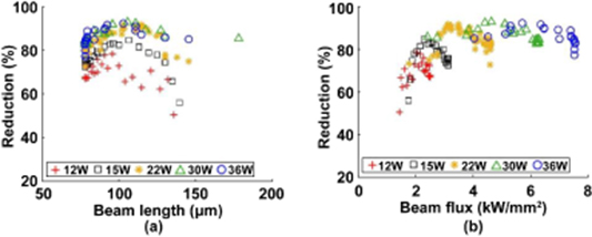
Figure 7. Dual-laser roughness reduction with different total powers.
Download figure:
Standard image High-resolution imageSimilar to the results in the single-laser experiment, the dual-laser set-up has a maximum roughness reduction increasing with higher laser power when laser power is below 22 W. The maximum roughness reduction then saturates around 90% at a total laser power of 22 W. Beyond this laser power, beam flux exceeds the ablation threshold and a small amount of surface material evaporation is observed when two 11 W lasers overlap.
For a constant total laser power, the roughness reduction first increases then decreases with longer beam length. Longer beam length creates a longer molten pool and a longer period of time for melted material to move. However, when the beam length is too long, two separate hot spots exist in the combined 'stretched' beam. In such case, two separated molten pools could lead to the decrease in the polishing performance.
In figure 7(b), the roughness reductions are plotted with respect to the beam flux. The beam flux for constructed beam is defined in the equation (3). Similar to the results in figure 6(b), beam flux below 1 kW mm−2 results in no polishing. Roughness reduction generally increases from 50% to 90% with beam flux increasing from 1 to 3 kW mm−2 as longer molten pool is created with the higher beam flux. For each power, the reduction percentage peaks at 90%. Then the reduction starts to drop with further increasing beam flux. This is because the high beam flux corresponds to the short beam length in figure 7(a) and such short length limits the size of the molten pool.
3.3. Comparison between single laser and dual laser results
Figure 8 examines the roughness reduction at total powers of 12, 15 and 22 W between the single and dual laser experiments. The scanning speed is 30 mm s−1 for both single-laser and dual-laser experiments. Results are characterized with respect to the beam length as defined in figure 4. Each individual data point is averaged over eight results. Standard deviation is <5% so we only show the average value for clarity.
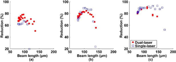
Figure 8. Overall roughness reductions between single beam and two beams set-ups at (a) 12 W, (b) 15 W and (c) 22 W.
Download figure:
Standard image High-resolution imageAt 12 W laser power, as in figure 8(a), the dual-laser set-up has a clear advantage over the single-laser set-up. While the single-laser set-up only has a peak roughness reduction around 65%, the dual-laser set-up elevates the peak performance to above 80%. The dual-laser set-up also extends the usable beam length. For example, at the beam length of 110 µm, dual-laser set-up retained a decent amount of roughness reduction (>60%) while the reduction percentage falls below 20% for the single-laser experiment. This is because the constructed beam from the dual-laser set-up distributes more energy along the scanning direction. Therefore, the dual-laser set-up creates a longer molten pool compared to the single-laser at the same beam length.
With laser power increasing from 12 W to 15 W, the difference in roughness reduction between the dual-laser and single-laser becomes negligible as shown in figure 8(b). Higher beam flux at 15 W laser power diminishes the significance of rearranging the beam energy distribution, as the beam flux can sustain a large enough molten pool for the defocused single-laser beam. Therefore, both the single-laser and dual-laser can achieve peak reduction around 90 %.
With an even higher laser power of 22 W, single-laser and dual-laser set-ups show similar trends with respect to beam length. The reduction percentage of the dual-laser set-up begins to fall with longer beam length whereas the single-beam set-up remains 90% reduction until 150 µm beam length. The drop in performance of the dual-laser is because the large distance between the two laser beams results in separated hot spots in the combined beam, while high laser power provides sufficient beam flux for the single-beam set-up even when the beam is defocused to 150 µm diameter. However, evaporation exists at 22 W laser power. Therefore, smaller laser energy is required to avoid evaporation.
We believe the improved roughness reduction at 12 W shown previously is a result of longer molten pools created by the combined beams. To demonstrate this, a closer look at the surface features with distinctive wavelength is shown in figure 9. A fast Fourier transform (FFT) converts the height profiles from the spatial domain into the frequency domain and reveals the two wavelengths at around 85 µm and 40 µm (see figure B1 in appendix B in the supplementary material). The original rough surface with two the wavelengths can also be observed in figure 2(c). The amplitudes of the 85 µm and 40 µm wavelengths before and after polishing are recorded from the FFT to calculate the reduction percentage at these two specific wavelengths.
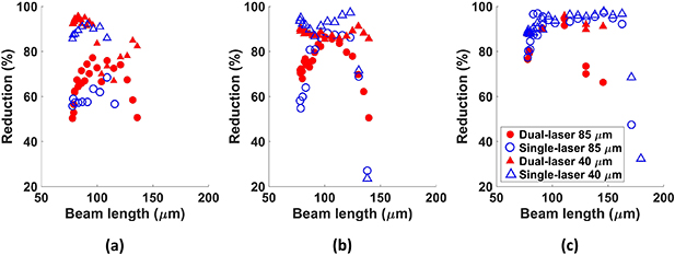
Figure 9. Roughness reductions at 85 µm and 40 µm surface wavelengths between single beam and two beams set-ups at (a) 12 W, (b) 15 W and (c) 22 W.
Download figure:
Standard image High-resolution imageAt 12 W total laser power, the reduction percentages for the 40 µm wavelength surface roughness are similar between the single-laser and dual-laser set-ups, as shown by the blue and red triangles. These results suggest both the single-laser and the dual-laser create molten pools larger than 40 µm to smooth the 40 µm wavelength surface features. Therefore, the main contribution to the improvement of the overall reduction in figure 8(a) is from the difference in reduction percentages at the 85 µm wavelength spatial regime, as shown by the red and blue circles in the figure 9(a). Clearly the dual-laser set-up both achieves higher maximum reduction percentage and extends the usable beam length region for the 85 µm wavelength features. The reduction percentage at the 85 µm wavelength regime indicates that the dual-laser set-up creates a sufficiently long molten pool to redistribute the 85 µm wavelength features as the combined beam rearranges the beam energy along its moving direction.
At 15 W total power, the results for both 85 µm and 40 µm wavelengths collapse together, aligned with the results in the overall reduction from figure 8(b). The increase in the beam flux from the higher laser power helps both single-laser and dual-laser beams to create molten pools longer than 85 µm. Therefore both set-ups reach maximum roughness reduction above 80% for the 85 µm features.
At 22 W total power, the roughness reduction for 40 µm wavelength surface features are similar between the single-beam and dual-beam experiments, while reduction to 85 µm drives the difference in the overall reduction percentages. It is believed that two hot spots exist in the dual-laser's combined beam when the beam length is beyond 120 µm and cause the polishing performance to decline.
3.4. Simulation results
Figures 10 and 11 show the results from COMSOL® simulations for the dual-laser set-up at 12 W total power and 30 mm s−1 speed. Figure 10 shows the temperature distribution of the symmetrical plane at different beam length in the dual-laser experiment. It is clear that with the increasing in the beam length from 78 µm to 121 µm, the molten pool becomes longer and shallower. However, with further increasing the beam length, the energy density is no longer large enough to sustain a molten pool and two small, separated molten pools are observed. Thus, substantial melting does not occur when the beam length is stretched to 146 µm.
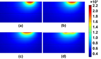
Figure 10. Simulation results of temperature (in K) distribution on the symmetrical plane, at beam lengths of (a) 78 µm, (b) 100 µm, (c) 121 µm and (d) 146 µm. Laser is moving from left to right.
Download figure:
Standard image High-resolution image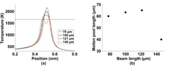
Figure 11. Simulation results of (a) molten pool temperature for different beam lengths and (b) molten pool length vs beam length at 12 W dual-laser set-up. Dash line in (a) represents the melting temperature at 1660 K. In (b) the molten pool length at 146 µm is the summation of the lengths of the two separated molten pools.
Download figure:
Standard image High-resolution image
Figure 11(a) plots the temperature at the centerline of the molten track at different beam lengths and the dash line is the melting temperature for SS316. When the beam length is longer, the maximum temperature drops and temperature gradient is smaller. A longer molten pool also provides a longer melting duration for the molten materials to relocate, corresponding to improved smoothening when the beam length increases in figure 8(a). However, when the beam length is too large, two hot spots are created and smaller molten pools are resulted as shown in figure 11. This is consistent with the drop in polishing performance when the beam length is too long.
Figure 11(b) shows the molten pool length with respect to the beam length. The molten pool length increases with longer beam length until the beam length over 130 µm. As the distance material can travel in the molten pool is proportional to the total length of the molten pool, polishing performance, especially for the 85 µm wavelength regime improves when beam length increases from 78 µm to 120 µm. Further increasing the beam length reduces the beam flux and creates two small, separated molten pool polishing. The molten pool then is not long enough to redistribute the 85 µm surface features. Therefore, performance decreases dramatically in experiments when beam length is above 120 µm as shown in figure 8(a).
In summary, the simulation results, especially the modeled molten pool lengths explain the roughness reduction change with respect to beam length of the dual-laser set-up at 12 W power and 30 mm s−1 scanning speed. Increasing the beam length up to 120 µm creates a longer molten pool that improves the polishing results. Above that critical polishing performance is worse as smaller, separated molten pools are created.
4. Conclusion
In conclusion, we present a method to combine two relatively low-power continuous-wave laser beams into a single elliptical beam for laser polishing. By carefully controlling the scan speeds and time delays between the two continuous wave beams, we can adjust intensity distribution of the combined beam. Experiments with a single laser beam at different focal offset distances are also conducted to compare the results with those using two beams.
For single laser beam experiments, the roughness reduction first increases then decreases with increasing beam diameters when the power and scan speed are constant. The maximum roughness reduction for a constant power increases with larger power, and saturates at around 90%, when the laser power is larger than 15 W.
For the dual-laser set-up, the correlation between roughness reduction and beam length is similar to the correlation in the single beam experiment. The maximum roughness reduction is also capped at around 90% when total laser power is higher than 15 W. During our experiments, various scan speeds do not affect the reduction percentage significantly.
We observe improvements of the dual-laser set-up over the single-laser set-up at lower total power, for example at 12 W. When we increased laser power, the dual-laser set-up does not show significant improvement over single-laser set-up in polishing performance. A detailed FFT analysis shows that the main difference is the polishing results at longer (85 µm) rather shorter (40 µm) spatial wavelength roughness. The FFT analysis, together with the simulation results, suggested that the dual-laser setup is efficient in rearranging the laser beam energy, thus creating a longer molten pool to redistribute the 85 µm wavelength features at 12 W laser power.
At the same time, evaporation is observed with a high-speed camera when the laser power is at or above 22 W. Therefore, dual-laser set-up improves the performance at low laser power and is able to avoid the surface material evaporation. The dual-laser set-up is also particularly useful for low-power laser polishing processing, for example when the laser sources are limited to low-power laser diodes.
Acknowledgments
This study was supported by Princeton University Eric and Wendy Schmidt Transformative Technology Fund. This simulation was funded by Comunidad de Madrid Project ADITIMAT-CM (S2018/NMT-4411) and Universidad Politécnica de Madrid Research Grant (EST-PDI-19-A1JMBI-26-T4MNY9). The authors also want to thank Luc Deike for valuable discussions. The authors acknowledge the use of Princeton's Imaging and Analysis Center, which is partially supported by the Princeton Center for Complex Materials, a National Science Foundation (NSF)MRSEC program (DMR-1420541), for the SEM image acquisition.