
Abstract
Difficult-to-machine materials (DMMs) are extensively applied in critical fields such as aviation, semiconductor, biomedicine, and other key fields due to their excellent material properties. However, traditional machining technologies often struggle to achieve ultra-precision with DMMs resulting from poor surface quality and low processing efficiency. In recent years, field-assisted machining (FAM) technology has emerged as a new generation of machining technology based on innovative principles such as laser heating, tool vibration, magnetic magnetization, and plasma modification, providing a new solution for improving the machinability of DMMs. This technology not only addresses these limitations of traditional machining methods, but also has become a hot topic of research in the domain of ultra-precision machining of DMMs. Many new methods and principles have been introduced and investigated one after another, yet few studies have presented a comprehensive analysis and summarization. To fill this gap and understand the development trend of FAM, this study provides an important overview of FAM, covering different assisted machining methods, application effects, mechanism analysis, and equipment design. The current deficiencies and future challenges of FAM are summarized to lay the foundation for the further development of multi-field hybrid assisted and intelligent FAM technologies.
Highlights
The recent advancements of the field-assisted machining techniques are reviewed.
Basic principles, equipment design, and typical applications of different field-assisted machining methods are summarized.
The rational selection and effectiveness of energy field in field-assisted machining are presented.
Challenges and prospects of field-assisted machining are orchestrated.
Export citation and abstract BibTeX RIS

Original content from this work may be used under the terms of the Creative Commons Attribution 4.0 license. Any further distribution of this work must maintain attribution to the author(s) and the title of the work, journal citation and DOI.
1. Introduction
Improving product quality and precision is the eternal pursuit of modern manufacturing science and technology [1]. With the rapid development of advanced optical and electronic technologies in semiconductor, photonics, aerospace, and other fields, core components made of difficult-to-machine materials (DMMs), including crystals, ceramics, superalloy, glass, etc, have emerged as significant consumption items for numerous international research projects. To meet the application requirements within these fields, core components necessitate achieving ultra-precision machining with extremely low damage. Its obvious characteristics are surface roughness Ra < 1 nm and almost damage-free surface and subsurface [2].
The characteristics of DMMs include high strength, chemical inertness, and good wear resistance. Consequently, they have long been considered difficult to machine due to their limited surface integrity, increased tool wear, and lower machining efficiency. The traditional machining process route for DMMs components involves grinding for forming, followed by lapping to remove damage and finally modifying and polishing [3]. While this process can generally meet the requirements of high-precision and low-damage surface processing, it faces a contradiction between material removal efficiency and damage removal effectiveness. Grinding forming introduces micron-scale surface damage which necessitates small removal amounts to achieve high-quality and low-damage surface processing. This inevitably reduces processing efficiency and increases costs [4]. In addition, traditional process routes are not suitable for DMM components with complex curved surfaces and diverse functional micro-nano structures. Diamond cutting can achieve a high degree of freedom, high efficiency, and high precision machining, and is an effective method for machining DMMs components [5]. It is an effective method to replace the grinding forming process to prepare DMMs with complex surfaces. Nevertheless, the machined surface is prone to defects such as cracks and sub-surface damage during the cutting process, which compromises the surface integrity of the workpiece thereby limiting performance improvement of DMMs components [6]. Additionally, severe tool wear occurs during diamond cutting leading to reduced tool service life [7]. Therefore, it is urgent to break through the bottleneck of traditional machining technology.
In recent years, non-traditional machining technology that introduces laser, ultrasonic vibration, magnetic field, plasma, and other fields upon traditional machining technology has been gradually proposed, which is called field-assisted machining (FAM) technology. FAM, as an advanced manufacturing technique, has drawn emerging interests for its capability of reducing the influence of harmful factors in the machining process and enhancing machinability of DMMs. Depending on the process flow, FAM can be divided into two categories: field-assisted cutting (FAC) and field-assisted surface quality improvement methods. FAM can also be categorized based on the form of energy field application: applied to the workpiece (laser radiation [8], magnetic magnetization [9], ion implantation [10], etc), applied to the tool (tool vibration [11] and tool magnetization [12]), and applied to the workpiece and tool at the same time [13–15].
Figure 1 shows the milestone timeline and tendency of FAM development. In terms of FAC, it began with ultrasonic vibration cutting (UVC) technology [16] in the 1960s, and has since developed into various techniques such as laser-assisted cutting (LAC) [17], magnetic field assisted cutting (MFAC) [18], and elliptical vibration cutting (EVC) technology [19] in subsequent decades. After entering the 21st century, technologies such as plasma assisted cutting (PAC) have been proposed successively, which have promoted the development of FAM technology. Especially in the past ten years, with the continuous progress of field control technology, in-situ laser assisted cutting (In-LAC) technology based on laser field high-precision regulation came into being [20], and hybrid FAC (HFAC) technology continuously emerged [14, 15], which further improved the surface machining quality and material removal rate of DMMs. Although FAC technology can achieve higher forming accuracy and suppress surface damage, it is not the final process for high-precision components. On the one hand, the multiple cutting of the tool will leave cutting textures on the workpiece surface [21], as well as the residue of damages [22], which will affect the machining accuracy and performance. On the other hand, the high-precision space trajectory of the machine tool determines the forming accuracy of the workpiece. In theory, the accuracy of the workpiece surface cannot exceed the accuracy of the machine tool [23]. Therefore, since the 1980s, non-contact field-assisted surface quality improvement methods represented by laser melting polishing (LMP) technology [24], magnetic field assisted polishing (MFAP) technology [25], ion beam figuring (IBF) technology [26], and atmosphere plasma processing (APP) technology [27] have been gradually proposed and finally realized ultra-precision, damage-free, and efficient machining of DMMs components.
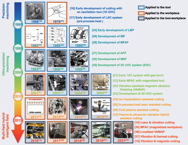
Figure 1. The milestone timeline and tendency of FAM development. Reprinted from [16], Copyright © 1968 Published by Elsevier Ltd. Reprinted from [17], with the permission of AIP Publishing. Reproduced with permission from [24] © The optical Society. Reprinted from [28], Copyright © 1990 CIRP. Published by Elsevier Ltd. All rights reserved. Reprinted from [26], Copyright © 1988 CIRP. Published by Elsevier Ltd. All rights reserved. Reprinted from [27], Copyright © 1993 Butterworth-Heinemann. Published by Elsevier Inc. All rights reserved. Reprinted from [29], Copyright © 1999 CIRP. Published by Elsevier Ltd. All rights reserved. Reprinted from [30], with the permission of AIP Publishing. Reprinted from [31], Copyright © 2000 Elsevier Science Ltd. All rights reserved. Reprinted from [12], Copyright © 2002 Elsevier Science B.V. All rights reserved. Reprinted from [32], Copyright © 2004 Elsevier Ltd. All rights reserved. Reprinted from [33], Copyright © 2005 CIRP. Published by Elsevier Ltd. All rights reserved. Reprinted from [10], Copyright © 2011 CIRP. Published by Elsevier Ltd. All rights reserved. Reprinted from [20], Copyright © 2012 Elsevier Inc. All rights reserved. Reprinted from [34], Copyright © 2012 Elsevier B.V. All rights reserved. Reproduced from [13], with permission from Springer Nature. Reproduced from [14]. CC BY 3.0. Reprinted from [35], © 2017 Elsevier B.V. All rights reserved. Reproduced from [36]. CC BY 4.0. Reproduced from [37], with permission from Springer Nature. Reprinted from [15], © 2021 The Society of Manufacturing Engineers. Published by Elsevier Ltd. All rights reserved.
Download figure:
Standard image High-resolution imageThis paper provides a critical overview of the wide range of applications of FAM and its current achievements and limitations, providing a basis for future research. The content organization of this paper is shown in figure 2. Section 2 introduces the characteristics of DMMs and their machining challenges. Sections 3 and 4 give a detailed introduction to the basic principles and processing performance of FAM, covering different FAM methods, material removal mechanisms, and equipment design. The common characteristics of different energy field assisted methods are analyzed and summarized in section 5. The future development directions of FAM are envisaged in section 6.

Figure 2. Content organization diagram of this review paper.
Download figure:
Standard image High-resolution image2. Difficult-to-machine materials
The continuous innovation of DMMs plays a crucial role in driving the advancement of FAM. DMMs, which refer to materials that generate excessive heat, exert large cutting force, and pose challenges in chip formation during machining operations, include functional crystals, structural ceramics, glasses, metal alloys, and composites. It is difficult to achieve ultra-precision machining of DMMs by conventional methods, as shown in figure 3. The main challenges are (1) poor surface integrity characterized by surface defects such as cracks, scratches, delamination, etc, (2) serious subsurface damage involving cracks beneath the surface layer along with amorphization and dislocations, and (3) shorten tool life resulting from issues such as tool breakage, tool wear, tool adhesion, etc. This section provides a comprehensive overview of the material properties, application areas, and machining challenges of DMMs, as shown in table 1.

Figure 3. Application fields of DMMs and their ultra-precision machining challenges. (a) Subsurface damage of single crystal silicon. Reprinted from [72], Copyright © 2008 Elsevier Inc. All rights reserved. (b) Surface defects in fused silica. Reproduced from [73], with permission from Springer Nature. (c) Serve tool wear in machining composite materials. Reproduced from [74], with permission from Springer Nature. (d) Large cutting force, thermal load and hardening of Ni-based alloys. Reprinted from [75], Copyright © 2008 Published by Elsevier Ltd.
Download figure:
Standard image High-resolution imageTable 1. Summary of the characteristics, application fields and machining challenges of DMMs.
| Classification | Characteristics | Application fields | Challenges | |
|---|---|---|---|---|
| Functional crystals | Si |
|
| Brittle fractures, sub-surface damage, flank tool wear, etc |
| KDP |
|
| ||
| ZnSe |
|
| ||
| Structural ceramics | SiC |
|
| Surface cracks, sub-surface damage and fast tool wear, etc |
| Al2O3 |
|
| ||
| ZrO2 |
|
| ||
| Glasses | Fused silica |
|
| A large number of brittle fractures, etc |
| Sapphire |
|
| ||
| BK7 |
|
| ||
| Metal alloys | Titanium alloy |
|
| Severe chilling and hardening, leading to fast tool wear |
| Ni-based alloy |
|
| Serious tool flank face wear and poor surface integrity | |
| WC |
|
| Brittle fracture and excessive tool damage | |
| Composite materials | SiCp/Al |
|
| Extremely severe tool wear, delamination, and poor surface quality |
| Cf/SiC |
|
| ||
| CFRP |
|
| ||
2.1. Functional crystals
Functional crystals such as Si, Ge, KDP, and ZnSe are kinds of materials with special optical and electrical properties, which have been widely applied to high-end industrial domains [38]. Si has superior semiconductor properties and optical properties. It has been commonly used in the production of semiconductors, photonics, and infrared optical components [39, 40]. KDP is mainly employed in high-power laser systems, optical instruments, and semiconductors due to their high transmittance and photoelectric coefficient [41]. ZnSe is an attractive infrared optical material with a high transmission rate at infrared wavelengths. It has been commonly used in lenses for night vision systems and windows of high-power CO2 laser [42]. However, this kind of material has the problems of low toughness and high brittleness [43]. It is extremely hard to achieve ductile machining without cracks on the workpiece surface [44].
2.2. Structural ceramics
Structural ceramics such as SiC, ZrO2, and Al2O3 are ceramic materials with various superior features that include high hardness and strength, good corrosion resistance, low thermal conductivity, and thermal expansion coefficient [45]. Therefore, ceramics are used extensively in aerospace, automotive, and photonic [46]. Specifically, SiC is used to fabricate optical mirrors due to their large specific stiffness and thermal stability. It is considered the most promising material in aerospace [47, 48]. ZrO2 is usually used to make high temperature bearings and human teeth due to their excellent friction resistance and biocompatibility [49]. Al2O3 has good insulation. It has been mainly used to manufacture electrical parts [50]. However, due to the low fracture toughness and high hardness of ceramic materials, it is difficult to process. There are serious problems in the machining process, e.g. surface cracks, sub-surface damage, and fast tool wear, thus, it is difficult to obtain high-precision surfaces and meet industry demand [51].
2.3. Glasses
Glasses are an amorphous material with an open network structure consisting of silica molecules and a small amount of metal ions [52]. They have excellent mechanical, optical, and electronic characteristics. They have usually been prepared as precision optical components [53]. Specifically, BK7 glass and K9 glass, as typical hard brittle materials, have obvious high hardness and brittleness. They are widely used as reflecting mirrors [54, 55]. Sapphire has excellent corrosion resistance and transmittance. It is widely applied to optical displays and colorful LED [56]. Fused silica glasses have low thermal conductivity and expansion coefficient due to the irregular internal chemical bond connection structure. They are used extensively in optical devices, aerospace, and other fields, such as reflectors in astronomical telescopes and high-power laser optical lenses [57]. However, the high brittleness and hardness of glass cause a lot of brittle fractures during cutting. To prevent fracture cracks from extending to the target surface, glasses should be processed in ductile mode [58].
2.4. Metal alloy
The metal alloy represented by titanium alloy, Ni-based alloy, and tungsten carbide (WC) has good wear resistance and excellent strength, and is widely employed in the industry. Titanium alloy is used extensively in engine parts, medical implants, and high-speed aircraft parts due to its good corrosion resistance and high specific strength [59], but its machining deformation coefficient and thermal conductivity are small, serious chilling and hardening, leading to fast tool wear [60]. Ni-based alloy is widely used in aviation impellers, turbine disks, and high temperature fasteners due to its excellent oxidation resistance and good fatigue performance at high temperatures [61]. However, the work hardening and large cutting force lead to high cutting temperature, which is conducive to the propagation between carbon and Ni, accelerates the tool flank face wear and deteriorates the surface integrity [62]. WC, as a kind of hard-metal, is an ideal material widely used in forming tools, drilling bites, and electronic communications fields, because of its high hardness and good abrasion resistance [63]. Due to the brittle fracture of the workpiece surface and extensive tool wear, it is really difficult to use the traditional machining method for ultra-precision machining of WC [64].
2.5. Composite materials
Composite material is a kind of application material with great potential, including metal matrix composites (MMCs), ceramic matrix composites (CMCs), and carbon fiber composites (CFCs). MMCs (such as SiCp/Al) are mostly heterogeneous mixtures with metal as the matrix and non-metallic particles, whiskers, or fibers as the reinforcing phase [65]. So, it is distinguished by its high specific strength and low coefficient of thermal expansion [66]. It is widely used in defense weapons, aerospace parts, braking systems, etc. CMCs represented by Cf/SiC use continuous carbon fiber to toughen the ceramic matrix, which not only retains the advantages of light weight and good wear resistance of the ceramic material, but also prevents the material from violent fracture failure. It is gradually applied to aircraft, braking systems and other fields [67]. CFCs (such as CFRP) have the benefits of a high specific strength and small thermal expansion coefficient. Therefore, it is widely used in aerospace, national defense and other fields [68]. However, due to the addition of the reinforcing phase, traditional machining of composite materials has a large cutting force, severe tool wear, and easy to generate machining defects such as burrs [69], delamination [70], and microcracks [71].
3. Field-assisted cutting technologies
FAC technology integrates energy fields such as thermal, ultrasonic, magnetic, and flow fields to make up for the shortcomings of traditional machining techniques in DMMs. At present, a series of research on FAC has been carried out on the processing principle, material removal mechanism, equipment, and other aspects. In this section, FAC technologies such as laser assisted, ultrasonic vibration assisted, magnetic field assisted and plasma assisted are summarized in detail.
3.1. Laser assisted cutting technology
As temperature increases, the hardness and brittleness of materials generally decrease. This makes thermal assisted cutting (TAC) an attractive option for improving the machinability of DMMs. Several practical heat sources such as laser beam, gas torch, furnace and induction heating have been widely used in TAC. The laser gets the most attention because it is easier than other heat sources to guide and focus on a point in the micron scale to achieve precise control of the thermal field. LAC has already proven successful in machining a variety of DMMs, including engineering ceramics [76], superalloys [77], and hard steels [78]. The position of the laser in relation to the tool is critical for LAC. Depending on whether the laser passes through the transparent tool, there are two main forms of LAC: pre-process-heat LAC (Pre-LAC) and in-process-heat LAC (In-LAC), as shown in figure 4. In the Pre-LAC scheme, the laser source is positioned ahead of the cutting tool and pre-heats the machining region prior to tool cutting [79]. This scheme inevitably introduces undesirable thermal effects and is generally applied in cylindrical turning with micron-scale material removal. In contrast, in the In-LAC scheme, the laser beam is directly delivered to the tool-workpiece contact area through a transparent diamond cutting tool. This approach is typically applied in nanometric [80]. Another difference between these two schemes is the absence of cutting fluid. To ensure effective heating of materials and prevent contamination of the light path, Pre-LAC is generally unsuitable for the use of cutting fluid. The In-LAC scheme with high integration of cutting tool and light source can solve the above shortcoming perfectly.

Figure 4. Schematic diagram of (a) Pre-LAC and (b) In-LAC.
Download figure:
Standard image High-resolution image3.1.1. Types of LAC
3.1.1.1. Pre-process-heat laser assisted cutting.
In Pre-LAC process, the laser source directly radiates the surface to be cut, achieving the softening effect of the workpiece by heating to an evaluated temperature, and the machine tool completes the cutting motion to achieve ultra-precision machining of DMMs. As a result, the heat softens the shear zone of the workpiece, making it easier to separate the cutting chips from the substrate. The distance between the laser and the tool has a direct impact on the machining effect. Scholars have applied Pre-LAC technology to the processing of DMMs such as silicon nitride [81], ZrO2 ceramics [82], and fused silica glass [73]. The softening effect of laser radiation decreases the yield strength of the material, increases the ductility, and improves the surface quality of the DMMs [8]. Song et al [73] found that the workpiece processed with Pre-LAC had fewer surface defects, such as cracks and grooves, and exhibited improved surface quality and cutting performance compared to those cut with ordinary cutting (OC), as shown in figure 5(a). A commercial laser system called ILPAC, developed by Innolite GmbH Co., has been successful in achieving improved machining quality of silicon [83], as shown in figure 5(b). In the cutting experiment, to achieve a better laser softening effect, the distance between the laser and the tool was fixed to 0.5 mm. Compared with CM, the surface roughness of LAC can be reduced by up to 90.05%. However, cutting fluid is prohibited during Pre-LAC as it can interfere with the laser beam path and cause refraction issues. Additionally, the separation of the heating and cutting regions causes a large thermal affected area.

Figure 5. The principle, device, and machining results of LAC process. (a) Precision Pre-LAC. Reproduced from [73], with permission from Springer Nature. Reprinted from [79], © 2018 Published by Elsevier Ltd on behalf of The Society of Manufacturing Engineers. (b) Ultra-precision Pre-LAC. Reprinted from [83], © 2021 Elsevier Ltd. All rights reserved. (c) In-LAC in which the laser exits from the flank face. Reprinted from [86], © 2020 Elsevier Inc. All rights reserved. (d) In-LAC in which the laser exits from the rake face. Reprinted from [94], © 2022 Elsevier B.V. All rights reserved.
Download figure:
Standard image High-resolution image3.1.1.2. In-process-heat laser assisted cutting.
Conversely, the In-LAC method has gained widespread usage because it circumvents the disadvantages described above. Micro-LAM Co. developed a commercial OPTIMUS T1 system [20, 84–86]. The OPTIMUS T1 system, as shown in figure 5(c), has been successful in achieving the optical machining of silicon with a surface roughness of 1.05 nm in Ra [87]. Additionally, germanium can retain surface roughness of less than 2 nm RMS using In-LAC method [85]. Mohammadi et al [84] conducted taper cutting experiments on silicon and observed that utilizing the In-LAC could effectively eliminate the radial spokes caused by crystal orientation effects. This, in turn, led to a significant enhancement in the surface quality of the workpiece. Ke et al [80, 88] used a self-developed In-LAC system to study the machining performance of silicon. They discovered that In-LAC can greatly enhance the material's flexibility and workability [89], and the DBT depth of silicon was raised by 364% compared with OC. Using similar experimental methods, the crucial DoC of fused silica was raised from 82.06 nm to 324.03 nm, which resulted in the development of a smooth surface with a Sa of 19.4 nm with laser assistance [90]. Huang et al [91] shown that the laser thermal effect induced by In-LAC influences nitrided mold steel's mechanical properties, in which the nano-hardness and elastic modulus are decreased by 41% and 20% at 400 °C, respectively. Based on the Taguchi method, an experimental investigation was conducted to determine the optimal finish quality for WC, achieving a surface with 3.06 nm in Sa [92]. However, the high laser power used during In-LAC has the potential to cause local graphitization on the diamond tool [93]. You and Fang [94] introduced a novel In-LAC method, known as high effective laser assisted turning (HE-LAT), which involves refracting the laser beam at the rake face and cutting edge, and total reflection at the flank face, as shown in figure 5(d). Experimental results demonstrated that HE-LAT can eliminate surface fluctuations, and prevent diamond local graphitization by using lower laser power.
3.1.2. Cutting characteristics and mechanism in LAC
3.1.2.1. Material's mechanical response to laser radiation.
DMMs are difficult to process at room temperature, mainly because the ultimate yield strength is greater than the fracture strength, resulting in uneven plastic deformation. This problem can be eliminated by heating the material to its thermoplastic stage [96]. Dislocations facilitate the ductile deformation of brittle materials when the temperature is above the ductile-to-brittle transition temperature [72]. Considering that the bonding forces among atoms and grains in the material will diminish at elevated temperatures, the laser radiation induced thermal field will remarkably improve the material machinability. Many researchers have reported that there is a sharp decline in the hardness of DMMs as the temperature increases, as shown in figure 6 [97].

Figure 6. Vickers hardness of the typical DMMs against reciprocal temperature. Reprinted from [97], Copyright © 2001 Elsevier Science B.V. All rights reserved.
Download figure:
Standard image High-resolution imageFor most DMMs, the fracture toughness experiences a significant rise when the material reaches the brittle to ductile transition temperature. Additionally, heating can improve ductile machinability by lowering tensile strength and increasing fracture toughness [98]. It is observed that all DMMs undergo a transition from ductile to brittle mode during nano-scratching as the DoC increases [99]. The critical depth of the transition from the ductile mode to the brittle mode is called the critical ductile-brittle transition (DBT) depth. When the DoC exceeds the critical depth for machining DMMs, material removal is accomplished through the propagation and intersection of cracks [100, 101]. The critical DBT depth can be estimated by the empirical formula as follows [102]:

where b is a constant that depends on the tool geometry, E is the Young's modulus, H represents the hardness, KIC is fracture toughness. Obviously, increasing KIC and decreasing H will significantly increase the DBT depth, improving the plasticity of the material. Experimental research has confirmed that laser heating could enhance the DBT depth during diamond cutting [22, 80, 91]. In this way, the material removal rate can be improved significantly.
3.1.2.2. Temperature control under laser radiation.
Cutting temperature plays an important role in the surface finish quality and tool life of LAC. If the workpiece temperature is too low, the material is not softened sufficiently, leading to poor machined surface quality and serious tool wear. Furthermore, elevated cutting temperatures can lead to the graphitization of the diamond tool and subsurface damage on the workpiece [103]. Therefore, controlling the temperature distribution precisely is one of the key technologies of LAC. Ravindra [104] utilized liquid temperature lacquers to measure the temperature during LAC of silicon. Nonetheless, the measurement accuracy may be compromised by the exceedingly low tool speed. Due to the spatial resolution limitation of current thermal instruments, it is not feasible to accurately measure the temperature field of the heat-affected zone at the nanoscale [105]. As a result, developing a precise thermal simulation model using analytical methods or finite element methods is an excellent approach to calculating the thermal field in LAC.
Analytic method considers laser energy input, radiation, convection, cutting heat, and natural convection, as illustrated in figure 7 [106, 107]. The heat conduction differential equation can be expressed by [108]:
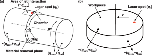
Figure 7. Thermal model during the LAM process. (a) Pre-LAC. Reprinted from [109], © 2019 Elsevier Ltd. All rights reserved. And (b) In-LAC. Reprinted from [107], Copyright © 2010 Elsevier B.V. All rights reserved.
Download figure:
Standard image High-resolution imagewhere  refers to the enthalpy in
  .
.  is the volumetric energy addition in
  .
.  is the rotational speed in
  .
.  refer to materials' density, specific heat, and thermal conductivity, respectively. And
  ,
,  , and
, and  are cylindrical coordinates.
The thermal energy input resulting from laser irradiation on the workpiece can be calculated by equation (3). qH, qconv, and qrad represent the absorbed laser energy, thermal convention, and radiation, respectively

The absorbed laser energy with a Gaussian distribution is given by equation (4), in which α, P, R represent the absorption ration, laser power and laser spot radius
Thermal convection can be described by equation (5) where  is the heat transfer coefficient

The radiation heat transfer between the surface and ambient air is calculated using equation (6) where  is Boltzmann's constant, and
  is emissivity of material

Rozzi et al [108] compared predicted surface temperature histories with measurements to verify the accuracy of the thermal model, which provides the basis for the parameters selection during LAC of nitride silicon. However, due to the complicated factors influenced the machining process, the accuracy of analytic method is not high enough.
The finite element analysis technique shows great potential in accurately calculating the temperature distribution during the LAC process, by considering the intricate boundary conditions and the thermal initial state. You et al [92] calculated the temperature distribution induced by laser heating, and applied this information to guide laser power selection for In-LAC of WC. Lin et al [90] developed a model to predict the temperature distribution of fused silica during laser heating, which was demonstrated to have high accuracy through temperature measurement with thermocouples. The findings indicated that the laser beam center had the highest temperature, which decreased rapidly with distance from the center of the beam. Ren et al [109] established a three-dimensional thermal model for Pre-LAC of fused silica. As shown in figures 8(a) and (b), the temperature in the cutting zone of the workpiece reaches 1490 K during Pre-LAC, while the temperature at the tool nose reaches 510 K. The temperature field during In-LAC found that there is a small influence area on the workpiece surface, with the majority of heat distributed in a semicircular region on the subsurface, as shown in figures 8(c) and (d) [80]. Compared to the temperature field produced during Pre-LAC, the heat affected zone is smaller and the temperature is higher due to the smaller diameter of the laser spot during In-LAC.

Figure 8. Simulation temperature in (a) and (b) Pre-LAC of fused silica. Reprinted from [109], © 2019 Elsevier Ltd. All rights reserved. And (c), (d) In-LAC of silicon. Reproduced from [80], with permission from Springer Nature.
Download figure:
Standard image High-resolution image3.1.2.3. Mechanisms of laser assisted material removal.
The high temperature produced by laser irradiation during LAC improves the ductile machinability of DMMs. Macroscopically, the effect of the laser changes the material removal mechanisms from brittle fracture to ductile removal. Microscopically, laser irradiation might cause phase transition, which affects surface generation and subsurface deformation during LAC. Due to the large material removal scale of pre-LAC, the material removal mechanism at a microscopic scale is rarely discussed by scholars, and the cutting mechanism during In-LAC is discussed through systematic numerical analysis and experimental investigation [110].
Hydrostatic pressure and shear stress are created during diamond cutting, which facilitate a high-pressure phase transformation [111, 112]. The high-pressure phase exhibits excellent properties of electroconductivity and machinability due to a microstructural modification [113]. During the LAC process, the high-pressure phase transformation affects the formation of lattice structure in the chip and the machined surface. Molecular dynamics (MD) simulation and cross-sectional TEM observations found that laser assistance changes the transformation path of silicon, and the amorphous Si was directly generated from the Si-I rather than from the Si-II. The newly created amorphous Si experiences partial recrystallization and is converted into metastable Si-III and Si-XII phases through laser annealing [20]. The various pathways of phase transformation routes indicate that the material removal mechanism is dependent on temperature. Furthermore, the dislocation activity was increased by a factor of ∼8 × 10¹⁴ with laser assistance, which enhances the plastic deformability of the material, contributing to the rise of the critical DBT depth and the reduction of the subsurface damage [22, 80]. Liu et al [89] studied the subsurface damage evolution of single crystal silicon at elevated temperature by MD simulation and diamond cutting experiments, and found that as the cutting temperature increased, the shear resistance of the amorphous layer decreased and the self-lubricating effect of the amorphous layer became more prominent. This outcome is beneficial in suppressing the formation of subsurface damage, as shown in figure 9.

Figure 9. MD simulation of the machined surface (a) T = 300 K. (b) T = 1 200 K; TEM images of the subsurface in ductile cutting regions: (c) without laser-assisted cutting and (d) with laser-assisted cutting. Reprinted from [89], © 2021 The Society of Manufacturing Engineers. Published by Elsevier Ltd. All rights reserved.
Download figure:
Standard image High-resolution imageAs mentioned forward, the temperature field under different laser powers varies a lot, which influences the material removal mechanism. You et al [93, 94] found that the cutting shear band with grain slippage consistently occurs along the grain boundary due to the high toughness during diamond cutting of polycrystalline WC. When employing low laser powers in LAC, grain strength is weakened effectively due to the thermal effect, resulting in the formation of straight shear bands and improved grain refinement. Conversely, higher laser powers used in polycrystalline material removal predominantly exhibit extrusion without any discernible shear band and pure amorphous cutting chips. The difference of the surface generation process influences the subsurface damage. With laser assistance, the dense crystal defects in the affected layer of the machined WC caused by the severe grain deformation and stress release decrease, and the thickness decreases from ∼227.9 nm to ∼17.8 nm.
LAC is a highly effective approach to achieving superior machining quality on DMMs. The quality of machining is evaluated and optimized by assessing surface integrity, cutting force, tool life, and material removal rate, as summarized in table 2. The effectiveness of laser assistance is mainly from two perspectives: laser absorption rate and laser power. The workpiece material is required to have a certain absorption rate of the laser, and the critical temperature of the material softening modification is ensured by controlling the laser power. Future research on LAC can be carried out as follows: (1) exploring the tool wear inhibition mechanism through numerical simulation and molecular dynamics simulation. (2) Establishing a high precision temperature control model based on online laser absorptivity measurement. (3) Developing a LAC system that is easy to operate and more integrated, promoting its industrial application.
Table 2. Comparison of various LAC research.
| Researcher | Types | Materials | Main conclusions |
|---|---|---|---|
| Dandekar and Shin [95] | Precision Pre-LAC | SiCp/Al | Resulting in a 37% decrease in surface roughness, and an improvement in tool life ranging from 1.7 to 2.35 times compared to OC. |
| Song et al [73, 79] | Precision Pre-LAC | Fused silica | Providing a decrease in surface roughness by 13.68%, a reduction in cutting force by 53.61%, and an improvement in tool life by 38.79% at the optimal parameters. |
| Guo et al [83] | Ultra-precision Pre-LAC | Silicon (100) | Providing a 90.05% reduction in the surface roughness compared to OC at the optimal parameters. |
| Ravindra et al [20] | Ultra-precision In-LAC | Silicon (100)<110> direction | Resulting in greater depths of cut over OC and producing a machined surface with less subsurface damage. |
| Mohammadi et al [84] | Ultra-precision In-LAC | Silicon (111) | Bringing Ra down from 770 nm to 3.2 nm and eliminating the radial spokes. |
| Ke et al [80] | Ultra-precision In-LAC | Silicon (100) | Providing a 364% increase in critical DoC, an 87% improvement in surface roughness Sz and a 50% improvement in surface roughness Sa. |
| Lin et al [90] | Ultra-precision In-LAC | Fused silica | Providing a 294.9% increase in critical DoC and an 84.3% improvement in surface roughness Sa from 123.9 nm to 19.4 nm. |
| Huang et al [91] | Ultra-precision In-LAC | S136 mold steel | Providing a 61.5% improvement in the surface roughness Sa and a 29% improvement in tool life. |
| You et al [92–94] | Ultra-precision In-LAC | Tungsten carbide | Providing a 75% improvement in critical depth of no observed surface cracks, a 0.97 nm surface roughness Sa and a 40% reduction in residual stress. |
3.2. Ultrasonic vibration cutting technology
UVC technology is an innovative machining technology, which utilizes a transducer (magneto-strictive/piezoelectric ceramic) to transform electrical energy into mechanical vibration energy during the cutting process, so as to realize ultra-precision machining of DMMs [114]. UVC is an intermittent cutting method, which can achieve nanoscale material removal in each vibration cycle. UVC separation allows coolant to penetrate the tool-workpiece interface, reducing friction at the cutting interface and reducing cutting temperature. It is advantageous for achieving the high precise and high-efficient ductile mode removal, the suppression of subsurface damage, and reducing tool wear due to an increase in the material removing shear angle and a decrease in the cutting force and temperature in a primary cutting area [115]. UVC can be classified into three types based on their different vibration modes: one-dimensional UVC, two-dimensional UVC, and three-dimensional UVC, as shown in figure 10. This section summarizes the existing research results comprehensively according to different types. The recent study summary is shown in table 3.
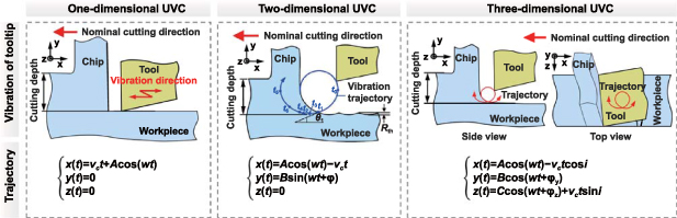
Figure 10. Schematic diagram of the UVC type.
Download figure:
Standard image High-resolution imageTable 3. Research conclusions of UVC technology.
| Researcher | Types | Material | Merits compared with OC |
|---|---|---|---|
| Zhou et al [114, 116] | 1D UVC | Glass | The critical DoC was increased to be approximately 1.5 μm. |
| Stainless steel | The application of ultrasonic vibration cutting resulted in enhancements to the cutting force, surface finish, and tool life. | ||
| Muhammad et al [117] | 1D UVC | Titanium | Enhanced machinability can be achieved by reducing cutting force, improving surface roughness of the machined workpiece, and generating shorter chips. |
| Zhang et al [118] | 1D UVC | Ni-base superalloy | The surface roughness and subsurface damage were reduced to Sa 4.815 nm and 0.190 μm from 60 nm and 2.27 μm, respectively. |
| Suzuki et al [119] | 2D UVC | Tungsten alloy | The maximum surface roughness was maintained below 100 nm Rz throughout a cutting distance of 50 m. |
| Tan et al [120] | 2D UVC | Ti6Al4V alloy | The surface finish achieved had a roughness value of less than 30 nm. |
| Zhang et al [121–123] | 2D UVC | Monocrystalline silicon | In elliptical vibration cutting of single crystal silicon, the nominal critical depth of cut for ductile brittle transition is over 12 times greater than that in conventional cutting. |
| Calcium fluoride | The critical DOC for DBT of CaF2 can be increased by 42 times with EVC. | ||
| Tungsten carbide | Realizing ductile mode machining and the finished surface is lower than 4 nm. | ||
| Kurniawan et al [124] | 3D UVC | Carbon steel | Lower cutting force and surface roughness |
| Shamoto et al [33] | 3D UVC | Harden steel | Successfully obtaining flat and spherical steel mirrors. |
| Lotfi et al [125] | 3D UVC | Ti6Al4V alloy | The surface roughness variation generated by 3D-UVC is significantly lower than that produced by OC. |
3.2.1. Types of UVC
3.2.1.1. One-dimensional UVC.
In one-dimensional (1D) UVC, ultrasonic vibration can be introduced separately to the cutting tool in the cutting direction [118], feed direction [126], and radial direction [127] according to the vibration direction; the principle schematic is depicted in figures 11(a)–(c) [128]. Skelton [16] proposed a linear vibration cutting technique, which involves machining with an assisted vibration having a linear motion in the nominal cutting direction. They found that applying a constant frequency ultrasonic vibration can significantly reduce the cutting force and temperature, improve tool life and machined surface quality. Zhou et al [114] designed a classical 1D linear UVC device. And the groove cutting experiments were applied to investigate the effect of tool vibration on the DBT of glass. The groove cutting experiments were performed in glass to study the impact of tool vibration on the DBT of glass. The results showed that the critical DoC was about 1.5 μm.
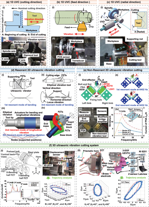
Figure 11. Schematic of the UVC system. (a) 1D UVC (ultrasonic vibration on cutting direction). Reprinted from [118], © 2022 Elsevier Inc. All rights reserved. (b) 1D UVC (ultrasonic vibration on feed cutting direction). Reproduced from [126], with permission from Springer Nature. (c) 1D UVC (ultrasonic vibration on radial direction). Reprinted from [127], © 2019 Elsevier Ltd. All rights reserved. (d) Resonant 2D UVC. Reprinted from [29], Copyright © 1999 CIRP. Published by Elsevier Ltd. All rights reserved. Reprinted from [130], © 2021 Elsevier B.V. All rights reserved. Reprinted from [135], Copyright © 2012 Elsevier Inc. All rights reserved. (e) Non-resonant 2D UVC. Reprinted from [131], © 2019 The Society of Manufacturing Engineers. Published by Elsevier Ltd. All rights reserved. (f) Schematic of the 3D UVC system. Reproduced from [124], with permission from Springer Nature. Reprinted from [137], © 2020 Elsevier Inc. All rights reserved.
Download figure:
Standard image High-resolution imageZhou et al [116] also investigated the machinability of steel alloys with UVC and the results showed that the cutting force, surface finish, and tool life were improved compared with OC. Muhammad et al [117] carried out titanium alloy with ultrasonically assisted turning and found enhancements in both the surface roughness of the machined workpiece and the generation of chips. Zhang et al [118] studied the machinability of Ni-base superalloy by UVC. And the experimental results showed that the surface roughness and subsurface damage were reduced to Sa 4.815 nm and 0.190 μm from 60 nm and 2.27 μm, respectively. However, the 1D UVC has shortcomings in that the tool edge would scratch the machined surface and suffer from severe alternating stress, which impairs surface quality and tool life in the process of separation [129].
3.2.1.2. Two-dimensional UVC.
To address the problems of 1D UVC, Shamoto and Moriwaki [19, 29] proposed the two-dimensional (2D) EVC technology which vibrating direction including parallel to cutting direction and cutting depth direction. The two dimensional elliptical vibrator device can be classified to resonant [130] and non-resonant [131], as shown in figures 11(d) and (e).
The resonant vibration device demands precise positioning of the tool (or workpiece), and the resonance frequency of the transducer must align with the working frequency [129]. Moriwak and Shamoto [132] proposed the first EVC device in the ultrasonic frequency in 1995, as shown in figure 11(d-i). The device is mainly composed of a square beam and two symmetrical cylindrical rods. Two pairs of piezoelectric plates are symmetrically arranged on the four sides of the square beam to drive the whole device to produce first-order bending in two perpendicular directions. The standing wave nodes of the square beam are selected as the supporting position, the tool tip is fixed on the edge of the cylindrical rod and generates the locus of vibration when the vibrator is working. Cutting experiments of oxygen free copper were conducted to verify the performance of the device. The results found that the cutting force of EVC is significantly decreased and the cutting thickness is thinner than that of OC. Shamoto and Moriwaki [29] developed the above elliptical device in 1999. The square beam is replaced by a six-prism beam, and the original cylindrical rod is instead by a stepped cylindrical rod (see figure 11(d-ii)). The piezoelectric plates are attached to the two sides of the six-prism beam, and the device works in two mutually perpendicular third-order bending vibration resonance modes. The fixed supporting point of the device must be selected at the node position of the bending vibration mode of the device to avoid the supporting structure affecting the bending mode of the transducer. The improved EVC device has been realized ultraprecision cutting hardened steel successfully. Suzuki et al [119, 133] cooperated with Taga Electric Co. to develop the latest EVC device, as shown in figure 11(d-iii). A bolt clamped Langevin type transducer (BLT) is used to actuate the device, which consists of PZT actuators sandwiched between metal cylindrical parts. Meanwhile, the device with a compact structure works in the composite mode of second-order longitudinal vibration (cutting depth direction) and fifth-order bending vibration (cutting speed direction). The elliptical vibration track is located in the direction of DoC and cutting speed which is convenient for tool installing and cutting experiments. The working frequency and amplitude of this device are 38 kHz–42 kHz and 0–4 μmp-p. However, the manufacturing and assembling of this device is difficult, which needs additional dedicated controllers to decouple the longitudinal-bending vibration modes in the two perpendicular directions and achieve modal degeneracy of these two vibration modes [134].
Guo and Ehmann [135] designed a tertiary motion generator by combining two longitudinal vibration modes, as shown in figure 11(d-iv). The device is composed of two sandwich-type longitudinal ultrasonic transducers crossed at 60° and coupled in the output by a flexible hinge, which can realize the tool's high-frequency elliptical vibrating with 28 kHz on the plane formed by its normal line and tangent line. The device has generated micro/meso-scale features successfully, while the coupling performance of two-direction vibration is poor, resulting in serious energy loss, and the considerable size of structure will limit its industrial application. As for the non-resonant UVC system, it operates at a frequency lower than the system's initial natural frequency [11]. Within them, Wang et al [131] designed an ultrafast 2D non-resonant cutting tool to fabricate the micro-structure surface, as shown in figure 11(e). The tool trajectory measurement experiments were carried out to evaluate the device performance. Tests were conducted at both low (200 Hz) and high (5.5 kHz) frequencies. The results showed a favorable agreement with the designed and measured trajectories. Furthermore, the effect of elliptical inclination angle on ductile cutting was analyzed, and it was found that the inclination angle of 135° is the most suitable for ductile cutting.
Based on the above innovative two-dimensional elliptical cutting vibration device, lots of scholars have carried out cutting experiments. Suzuki et al [119] used the resonant EVC device to machine tungsten alloy molds. Throughout a cutting distance of 50 m, the maximum surface roughness was maintained below 100 nm Rz. Tan et al [120] applied the EVC technology in cutting Ti-6Al-4V. The experiments indicated that the tool wear was obviously restrained and the surface quality was significantly improved when the finished surface was less than 30 nm. Zhang et al [122] studied the single crystal silicon machining in ductile by adopting the EVC technology. The grooving experiments demonstrated that the nominal DBT depth in EVC is more than 12 times higher than that in OC. Zhang et al [123] studied the machinability of CaF2 by EVC. The results demonstrated that the critical DoC for the DBT is increased by 42 times compared with that for OC. Zhang et al [121] carried out a fundamental study on the ductile machining of tungsten carbide. The results showed that the finished surface roughness is lower than 4 nm by EVC in ductile mode machining. 2D UVC has achieved micron/nano-scale surface microstructure machining of DMMs.
3.2.1.3. Three-dimensional UVC.
The three-dimensional (3D) UVC system was proposed based on the research of two dimensional EVC. Zhang and Song [136] proposed a novel ultrasonic EVC mechanism with decoupled 3D and fabricated a prototype device. And the vibration characteristics test experimental results showed that the performance of the innovative 3D EVC mechanism is satisfactory. Kurniawan et al [124] developed a sandwiched piezoelectric actuator-based holder for a resonant 3D ultrasonic elliptical vibration tool (UEVT). The 3D-UEVT produced a peak-to-peak amplitude of about 0.8 μm in two bending directions and a range of 0.3 μm to 0.5 μm in the longitudinal direction, as shown in figure 11(f-i). And the microgroove pattern experiments of AISI 1045 carbon steel were carried out. The results showed the novel 3D ultrasonic vibration tool holder has lesser cutting force and surface roughness compared with OC. Kurniawan et al [137] designed a 3D-UEVT holder based on coupled resonant modes, as shown in figure 11(f-ii). And the amplitude in the x-, y- and z-axis directions is approximately reached to 0.42 μm, 0.5 μm, and 0.6 μm at a resonant frequency, respectively. Shamoto et al [33] proposed the 3 DOF ultrasonic vibration tool technology to machine hardened die steel. And this method can achieve the machining of sculptured mirror surfaces on hardened die steel. So far, the primary focus of the 3D UVC has been on the device's structural design and output stability, while the exploration of surface microstructure processing applications is gradually gaining attention [129].
3.2.2. Cutting characteristics and mechanism in UVC.
UVC is a periodic intermittent machining method, which is different from the cutting characteristics of conventional machining. These cutting characteristics change the material removal mechanism and can significantly improve the surface quality and machinability of DMMs. It is worth noting that high-dimensional UVC includes the cutting characteristics of low-dimensional UVC. In other words, the higher the dimension of UVC, the more cutting characteristics. Therefore, in order to explain different cutting characteristics in UVC, the cutting characteristics of 1D UVC, 2D UVC, and 3D UVC are described by numerical models in detail. Furthermore, it is helpful in revealing the mechanism of UVC, improving the machinability of DMMs according to the cutting characteristics.
3.2.2.1. Intermittent cutting characteristic of 1D UVC.
As shown in figure 12(a), in the UVC process, the tool only executes cutting in the time segment ta –tb , while it is in the uncut state at other times during one vibration period. The main characteristic of 1D UVC is intermittent cutting, which changes the OC process. Nath and Rahman [138] proposed the tool-workpiece contact ratio r to analyze this property. The intermittent cutting characteristics are described as follows:


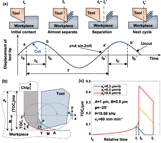
Figure 12. Characteristics of the 1D UVC and 2D UVC process. (a) Intermittent cutting state in 1D UVC process. Reprinted from [11], Copyright © 2007 Elsevier Inc. All rights reserved. Reprinted from [138], Copyright © 2008 Elsevier Ltd. All rights reserved. Mechanism of the 2D UVC process: (b) the geometric cutting model and (c) the variation of TOCt. Reprinted from [142], © 2021 Elsevier Inc. All rights reserved.
Download figure:
Standard image High-resolution imageCombining equations (7)–(9), the final equation is obtained as follows:
where  is nominal cutting speed. f (i.e. vibration period, T = 1/f) is frequency and A is vibration amplitude.
  is the time of initial tool-workpiece contact.
  is the time of initial separation of tool and workpiece.
It is worth noting that there are actual upper and lower limits of cutting speed to ensure the effectiveness of vibration cutting [129]. When the horizontal speed ratio (HSR = vc/2πAf) is less than 1, UVC is satisfied, otherwise it is OC (i.e. HSR > 1). Moreover, thanks to the existence of separation phenomenon in each vibration period, the cutting zone can be effectively cooled by air and cutting fluid, which makes the thermochemical wear of the tool to be suppressed. The ultra-precision machining of DMMs, such as ferrous metals, can be achieved by applying UVC technology [7].
3.2.2.2. Transient thickness of cut (TOCt) variation characteristic of 2D UVC.
In the 2D UVC process, the tool oscillates at an angular frequency  with vibration amplitude A of the cutting direction and amplitude B of the depth of cut direction. During the process of material removal in a cycle, the cutting path of the tool tip starts at point A, reaches the lowest point M of the trajectory, passes through the point D (i.e. initial contact between rake face and chip) and the friction reversal point E, finally separates the chip at the point F, accordingly in figure 12(b). In order to accurately clarify the tool trajectory, the displacement function of tool tip relative to workpiece in Cartesian coordinates can be described as follows:


Then, the velocity function of the tool tip can be obtained by deriving the time variable, as shown in equations (13) and (14):
where  and
and  represent the velocity of the nominal cutting direction and the depth of cut direction, respectively.
  is the cutting speed.
  is the phase shift. HSR directly affects the shape and thickness of undeformed chips. With the increase of HSR, the overlap of tool paths gradually decreases and the duty cycle gradually increases. If the HSR is greater than 0.32 and the cutting depth is greater than the vibration amplitude B, the tool will never break contact with the workpiece and the 2D UVC will no longer be effective [129].
Blake and Scattergood [139] found that when TOCt is less than a critical value (dc), the ductile-regime cutting can be achieved. Hence, it is critical to clarify the change of TOCt in 2D UVC. Zhang et al [140] proposed that TOCt represents the y-axis distance between the cutting edge and the surface remaining from the previous cutting cycle, and analyzed its numerical changes by the following equations:
where y is the displacement function of the tool tip along the y-axis. ap
is the nominal cutting depth. tp
is the time at which the tool tip passed point P during the previous cutting cycle.  is the tool rake angle.
It is evident that the value of TOCt undergoes continuous variation and is consistently less than  because of the overlapping cutting cycles. Hence, the cutting force becomes smaller because of the lesser material removal volume. Nath et al [141] found that the ductile machining of brittle materials can be achieved if the maximum value of TOCt (TOCtmax) is not greater than the dc. TOCtmax plays a critical role in the ductile-regime cutting of DMMs. Furthermore, Liu et al [142] investigated the variation of TOCtmax during one cycle. ti
was the time that TOCt reached the maximum value. When b> ap, TOCtmax would be slowly increasing with increasing ap
. Continue to enlarge ap, ti
would be a constant tD
dependent on the UVC system while TOCtmax increased quickly, as depicted in the figure 12(c).
because of the overlapping cutting cycles. Hence, the cutting force becomes smaller because of the lesser material removal volume. Nath et al [141] found that the ductile machining of brittle materials can be achieved if the maximum value of TOCt (TOCtmax) is not greater than the dc. TOCtmax plays a critical role in the ductile-regime cutting of DMMs. Furthermore, Liu et al [142] investigated the variation of TOCtmax during one cycle. ti
was the time that TOCt reached the maximum value. When b> ap, TOCtmax would be slowly increasing with increasing ap
. Continue to enlarge ap, ti
would be a constant tD
dependent on the UVC system while TOCtmax increased quickly, as depicted in the figure 12(c).
To further examine the impact of TOCt on the material removal mechanism, simulations were conducted to explore the nanoscale processing of 2D UVC on DMMs. Dai et al [143] utilized molecular dynamics simulations to investigate the subsurface quality and material removal of monocrystalline silicon during UVC processing. The simulation results indicated that UVC processing tends to induce ductile-mode cutting in silicon, which has a beneficial impact on tool longevity. However, it can also result in higher subsurface temperatures. Liu et al [144, 145] modified the classical molecular dynamics model to investigate the material removal mechanism in UVC of monocrystalline silicon. A single vibration cycle was described through an increment of the tool vibration amplitude and nominal depth of cut. The results indicated that within a single vibration cycle, the primary mechanism of material removal transitions from extrusion to shear, see figure 13. Tensile stress is the main cause of subsurface damage in the shear stage. Furthermore, increasing the radius of the cutting edge, decreasing the velocity ratio of the nominal cutting and DOC direction, and increasing the amplitude of the cutting direction will delay the extrusion-shear transition.
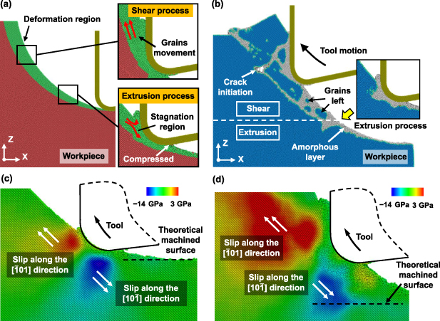
Figure 13. Illustration of the 2D UVC simulation. (a) Snapshots of extrusion and shear process. (b) Recognition of crystal structures and the analysis of the stress distribution in the subsurface of the workpiece during both the (c) extrusion stage and (d) shear stage. Reprinted from [145], © 2021 Elsevier Ltd. All rights reserved.
Download figure:
Standard image High-resolution image3.2.2.3. Oblique cutting characteristic of 3D UVC.
As illustrated in figure 14(a), there is the trajectory of the tool tip in 3D UVC. During one cycle, the tool starts to cut the workpiece at point t0, reaches the bottom point t1 in the y direction, where the velocity of the tool tip is zero. Finally, it is separated from the workpiece at the point t2. Then, the tool jump into the next cycle at point t3 [146].
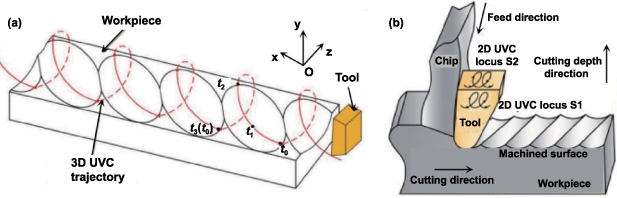
Figure 14. Characteristic of the 3D UVC process. (a) Kinematics model of tool cutting. Reproduced from [146]. CC BY 4.0. (b) The principle of 3D UVC. Reproduced from [147], with permission from Springer Nature.
Download figure:
Standard image High-resolution imageThere are three different vibration amplitudes of three perpendicular directions during the 3D UVC process. Similar to the motion analysis of the 2D UVC process, the tool tip path with the vibration can be depicted as:


The Cartesian coordinates of the relative tool and workpiece position along the nominal cutting, thrust, and feeding directions are represented by x, y, and z, respectively. The vibration amplitudes in the x, y, and z directions are denoted by A, B, and C, respectively. Time is represented by t and angular frequency by ω. The inclination angle is indicated by i, while the phase shifts of the vibrations in the y and z directions are represented by  and
and  , respectively.
Although the vibration trajectory becomes complicated, the cutting force will become smaller due to the newly added vibration direction. Compared to the orthogonal 2D UVC locus, 3D UVC also includes the oblique 2D UVC locus, as shown in figure 14(b). Due to the oblique cutting characteristic, the chip is pulled laterally, thereby decreasing the frictional thrust component that hinders the flow of the chip. In summary, not only is the friction between the tool and the chip reduced or reversed, but the thrust component is also further reduced in the 3D UVC process [33, 147].
In summary, with the change of machining mode, the contact mode between the tool and the workpiece during intermittent machining also changes. Compared to OC, UVC technology could significantly decrease cutting force, diminish tool wear, and enhance the surface machining precision of the workpiece. Nowadays, the UVC system has made a great deal of achievements. The advanced ultra-precise manufacturing companies, German Son-x, German Innolite, and Japanese Taga company have produced commercial products of UTS-2, ILSonic, and EL-50Σ, respectively. The 2D UVC has achieved micron/nano-scale surface microstructure machining of DMMs. The 3D UVC technology mainly concentrates on the structural design and output stability of the device, while research on the application of surface microstructure processing is gradually being explored. Meanwhile, attention should be given to future work on UVC technology: (1) in-depth research on the mechanism of high-precision surface formation, especially the influence of material deformation and tool impact on machining quality, (2) improving the UVC system stability, which can be conducted long time stable working, (3) increasing the vibration frequency and amplitude of the UVC system, which is beneficial to improve the machining efficiency for industrial applications.
3.3. Magnetic field cutting technology
MFAC is another energy FAM technique. At present, magnetic field assistance is mainly utilized in the processing of paramagnetic materials, such as titanium alloy, nickel-based alloy, and calcium fluoride (CaF2). In the magnetic FAM process, high-density magnetic field energy is applied to the material through non-physical contact, which has a certain impact on the performance of the material. Efficient removal of DMMs can be achieved by combining traditional processing techniques, resulting in high surface accuracy and minimal subsurface damage [148]. According to this characteristic, it can be predicted that it will have significant potential for applications in the field of material processing. Numerous researchers have carried out research on MFAC. Based on the classification of magnetized objects, MFAC is mainly divided into magnetized tool and magnetized workpiece. The recent study summary is shown in table 4.
Table 4. Research conclusions of MFAC technology.
| Researcher | Types | Material | Merits compared with OC |
|---|---|---|---|
| Xu and Liu [149] | Magnetized tool (high-speed steel) | Steel alloy | Improve tool durability by 1.5–3.0 times, under certain circumstances, tool life can be increased by 4–6 times. |
| Li and Mu [150] | W6Mo5Gr4V2 | The maximum friction coefficient is reduced by 45.8%, and the tool impact capacity is increased by about 10%. | |
| El Mansori et al [12] | XC38 | The mean width of the pits on the tool surface decreases by about 50% and the maximum depth decreases by about 75%. | |
| Jing and Tang [163] | Stainless steel | Improve tool durability by more than 4 times. | |
| Dehghani et al [151] | Steel alloy | After the magnetic field is applied, the wear on the tool flank is reduced by 94%. | |
| El Mansori et al [153] | Magnetized workpiece | 45 steel | The machinability has been improved with reduced cutting forces, improved surface roughness of the machined workpiece, and 2–3 times increase in tool life. |
| Yip and To [35, 154–158] | Ti6Al4V | The bottom surface roughness has been improved from 36.58 nm to 15 nm. Additionally, the maximum flank wear width is reduced by 23%. | |
| Wu et al [159] | Single crystal copper | The cutting-force ratio and friction coefficient on the rake surface have been reduced by 16%. Furthermore, the surface roughness has decreased on average from 16.2 nm to 15 nm. | |
| Guo et al [160, 161] | CaF2 | The surface pile-up effect was weakened by 10–15 nm. The DBT depth is increased from 512 nm to 664–806 nm when cutting along the crystal direction [122]. | |
| Single crystal copper | There was a significant decrease in cutting forces, with values decreasing from 3.2 N to 1.5 N. Additionally, the surface roughness Ra showed improvement, decreasing from 31.2 nm to a range of 22.5–10.8 nm. | ||
| Xiao et al [162] | Nickel-based alloys | The surface roughness Ra is improved from 23 to 13 nm. |
3.3.1. Types of MFAC
3.3.1.1. Magnetized tool.
Enhancing cutting tools has consistently been a crucial research subject in the whole mechanical manufacturing industry. Enhancing the wear resistance and cutting performance of cutting tools is critical in determining processing efficiency, surface quality, and component cost. High-speed steel material continues to be a vital component in the mechanical manufacturing industry due to its exceptional comprehensive performance in strength, toughness, and processing capacity. Therefore, the early magnetization treatment of tool materials is mainly concentrated on high-speed steel tools. Muju and a Ghosh [18] conducted a study on MFAC cutting steel alloys. By calculating the tool wear gain coefficient under the magnetic field, they found that the wear gain coefficient was positively correlated, and the magnetic field was conducive to reducing the wear of high-speed steel tool. Xu and Liu [149] found that magnetization treatment of high-speed steel tool can improve its durability 1.5–3.0 times, under certain circumstances, tool life can be increased by 4–6 times. Li and Mu [150] magnetized the high-speed steel tool by low frequency pulse magnetization, and discovered that the mechanical property of the magnetized tool material was improved. Magnetization can reduce the residual stress of the tool, thereby improving the durability of the tool. To further study the magnetic field on the tool to extend the life of the reasons, El Mansori et al [12] wound a 6 mm diameter DC coil outside the tool, the magnetic field intensity can be controlled by adjusting the current intensity, as shown in figure 15(a). It is found that the magnetic field can enhance the durability of cutting tools during the cutting process. Under the excitation of a high magnetic field, the mean width of the pits on the tool surface decreases by about 50% and the maximum depth decreases by about 75%.

Figure 15. The principle, device, and machining results of MFAC. (a) and (b) are magnetized tool assisted cutting. Reprinted from [12], Copyright © 2002 Elsevier Science B.V. All rights reserved. Reprinted from [151], © 2017 Elsevier B.V. All rights reserved. (c) is magnetized workpiece assisted cutting. Reprinted from [35], © 2017 Elsevier B.V. All rights reserved. Reprinted from [154], © 2017 Elsevier Ltd. All rights reserved. Reproduced from [156]. © IOP Publishing Ltd. All rights reserved.
Download figure:
Standard image High-resolution imageDehghani et al [151] designed an L-arm device for the MFAC of steel alloy. The L-arm device connects the tool to the workpiece, forming a closed-loop circuit that provides a consistently stable magnetic field for magnetizing the workpiece, as shown in figure 15(b). The findings from the experiment indicate that the wear of the tool flank is reduced by 94% after applying the magnetic field. Therefore, the current research results can show that MFAC can indeed improve the tool life. Magnetized tools can effectively inhibit tool wear and improve workpiece machining quality, but it is difficult to assess the influence of magnetic field on improving cutting performance. Meanwhile, it cannot be applied to non-magnetic cutting tools like diamond tools, so the application range is limited.
3.3.1.2. Magnetized workpiece.
In addition to the magnetization treatment of the tool, some scholars have also studied the magnetization treating workpiece during the machining process. El Mansori et al [152] studied the surface plastic deformation of MFAC steel alloys. It was discovered that as the magnetic field strength increased, the thickness of the second deformation zone increased, and the serrated degree of chips was greatly reduced. Subsequently, they also found that the utilization of the magnetic field improved the machinability of the workpiece material, altered the shear angle, shear strain, and cutting thickness ratio, and affected the contact condition between the tool and chip, and increased the tool life by 2–3 times [153]. In recent years, magnetic fields have been integrated into the ultra-precision diamond cutting process by some researchers to reduce the material swelling impact on the surface of machined titanium alloys. Yip and To [35, 154–158] installed two permanent magnets with a magnetic field intensity of 0.02 T on the machine tool. During cutting operations, the titanium alloy workpiece rotates within a magnetic field that is produced by the installation of two permanent magnets, as shown in figure 15(c). Under the influence of the magnetic field, there was a significant improvement in the surface quality of the workpiece. The accuracy of DoC, width, and radius of the cutting groove reached satisfactory over 98%. Compared with OC, the bottom surface roughness decreases from 36.58 nm to 15 nm [35]. There are many beneficial effects by introducing a magnetic field. The eddy current damping generated by the magnetic field not only dissipates the vibration energy at the tool tip but also decreases the cutting heat at the interface between the tool and titanium [158]. As a result, the negative impact on surface quality caused by brittle deformation is significantly reduced, leading to an improved surface quality in both the ductile and brittle deformation zones [155]. Moreover, the thermal conductivity of titanium alloy is low, which means that the high temperature at the processing interface makes the material melt, and the average grain diameter reduction rate is 20.3%, the grains of titanium alloy surface are effectively refined to improve the machining properties of titanium alloy [156]. The primary wear mechanism during cutting of titanium alloy is adhesive tool wear. With the assistance of a magnetic field, the adhesive wear of the tool is reduced and the maximum flank wear width is decreased by 23% [154].
Wu et al [159] introduced a magnetic field in the process of diamond cutting single crystal copper. The findings indicate that the magnetic field influences the metal cutting process by altering the cutting force, chip morphology, and surface finish. In comparison to OC, MFAC leads to an elevation in the induced Lorentz force, whilst the cutting force ratio and friction coefficient of the rake face are diminished by 16%. Additionally, the tribological behavior of the tool-chip contact interface is enhanced. Guo et al [160] attributed this process to the magneto-plastic effect, due to the application of magnetic fields, the plasticity of metals will undergo a significant alteration. Subsequently, they conducted experiments on CaF2 [161]. The micro deformation test under a weak magnetic field of 0.02 T confirmed the impact of magneto-plasticity on CaF2. Under the influence of the magnetic field, the surface stacking effect was weakened by 10–15 nm, and the dislocation density was about 30% lower than that without magnetic field, and the fracture toughness increased by 53.8%. Micro-cutting tests along the CaF2 (111) plane with different crystal orientations show that magneto-plasticity contributes to an increase in the DBT of the machined surface. The DBT depth is increased from 512 nm to 664–806 nm when cutting along the crystal direction ![$[11\bar 2]$](https://content.cld.iop.org/journals/2631-7990/6/3/032002/revision2/ijemad2c5eieqn26.gif) . Xiao et al [162] conducted the MFAC experiments on nickel-based superalloys. The experimental results indicate that the application of a magnetic field leads to an improved chip morphology in comparison to OC. The cutting force oscillations (Fc, Fa
, and Ff
) are markedly reduced by 90%, 88%, and 78%, respectively. The Ra surface roughness value increases from 23 nm to 13 nm, while the P-V value of the fan-shaped region of the machined surface undergoes a 49% reduction.
. Xiao et al [162] conducted the MFAC experiments on nickel-based superalloys. The experimental results indicate that the application of a magnetic field leads to an improved chip morphology in comparison to OC. The cutting force oscillations (Fc, Fa
, and Ff
) are markedly reduced by 90%, 88%, and 78%, respectively. The Ra surface roughness value increases from 23 nm to 13 nm, while the P-V value of the fan-shaped region of the machined surface undergoes a 49% reduction.
3.3.2. Cutting characteristics and mechanisms in MFAC.
Through the above research, it can be found that the machining process can benefit from various improvements when exposed to a magnetic field. However, the influence of the magnetic field on the properties of workpiece materials, especially the dynamic mechanical properties related to the machining process, has not yet reached a unified conclusion, which needs further study. So far, the explanation of the effect mechanism of MFAC is mainly focused on the following points:
3.3.2.1. Effect of eddy current damping.
During the OC process, the workpiece is affixed to the spindle and rotates at a predetermined speed. Vibration is an inevitable occurrence that can cause the tool tip and workpiece to deviate from their intended motion trajectory, resulting in undesired effects [164]. After the introduction of the magnetic field, as shown in figure 16(a), the workpiece rotates at a specific velocity within the magnetic field. There will be countless 'wires'cutting the magnetic induction line inside the workpiece, which will produce Lorentz force and make the workpiece in motion become a damping mechanism. The greatest role of the damping effect is to increase the difficulty of vibration of the workpiece, so the kinetic energy of the workpiece is converted into heat energy loss [165]. By reducing the vibration effect of the workpiece, the relative motion error between the tool and the workpiece is significantly decreased, which guarantees the precision of the machined surface [158]. Simultaneously, the relevant literature indicates that enhancing the strength of the magnetic field can enhance the damping effect and decrease the passive vibration during the cutting process.
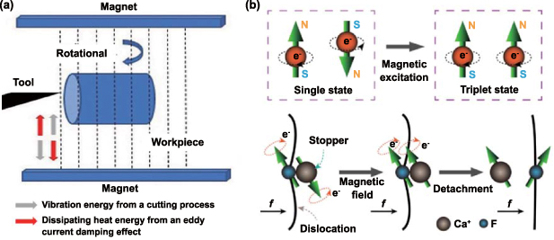
Figure 16. The effect mechanism of the magnetic field. (a) Effect of eddy current damping. Reproduced from [158], with permission from Springer Nature. (b) The magneto-plastic effect. Reprinted from [161], © 2022 Published by Elsevier Ltd on behalf of The editorial office of Journal of Materials Science & Technology.
Download figure:
Standard image High-resolution image3.3.2.2. Enhancement of thermal conductivity.
Numerous experimental investigations have demonstrated that the magnetic field utilized during cutting can considerably increase the thermal conductivity of the material. Currently, there exist two primary perspectives regarding the impact of magnetic fields on the temperature of the machining process. The first is based on the magnetic cooling effect, the magnetic domain direction confusion occurs in the demagnetization process, which absorbs a lot of heat [148]; the other is the explanation of the magnetic field heat conduction chain. This explanation is based on the phenomenon that the thermal conductivity of magnetic nanofluids in the magnetic field is significantly enhanced [166], while titanium alloy is a paramagnetic material, and a similar phenomenon can occur with titanium alloy [156]. These workpieces belong to metals or their alloys, and there are many magnetic particles inside these materials. These magnetic particles will become magnetized when exposed to a magnetic field. The particular manifestation is that these magnetic particles will align their own magnetic dipole moment with the direction of the magnetic field, thus forming a thermally conductive linear chain [35, 157]. These linear chains can promote the loss of heat generated by processing.
3.3.2.3. Effect of material properties.
In the MFAC process, the workpiece will undergo changes in material properties while under the influence of the magnetic field. From the perspective of metallographic structure, the grain size in the workpiece will change, and the magnetic field will refine the grain of the workpiece, thereby improving the surface microhardness. The enhancement of thermal conductivity inhibits the formation of accumulation edges and can also promote the refinement of workpiece grains [156]. Considering the tribological properties of the material, the application of an external magnetic field will cause the crystal's multi-domain configuration to transition to a single-domain configuration, reducing the diffusion activation energy, thereby increasing the dislocation motion inside the workpiece [12]. After the material surface accumulates defects, the wear effect is improved. From the perspective of the internal stress of the material, the magnetic treatment attributes to a rise in the dislocation activity of the workpiece, the dislocation's mobility is improved, and the material's plasticity is enhanced [167]. After the plastic softening of the material, the internal residual stress is eliminated. From the perspective of magneto-plastic effect and electron spin, there are often some lattice defects in the workpiece. These defects may also exist in non-singlet form or possess a low enough number of non-singlet states in the ground state, thus allowing them to interact with the external magnetic field [161]. When subject to a magnetic field, the free radical pair located between the dislocation and the stopper underwent a transition from a singlet state to a triplet state with minimal binding energy, as shown in figure 16(b). As a result, the dislocation is no longer bound by its spin-related forces, leading to the phenomenon of magneto-plasticity.
In summary, MFAC is a kind of FAC method that integrates materials, electromagnetic, heat transfer, and other disciplines. Compared with OC, the magnetic field can create eddy currents on the subsurface of the workpiece, which will produce damping effects during the cutting process. This damping effect can reduce workpiece surface corrugations and surface roughness caused by tip related vibration. Besides, the magnetic field can enhance the thermal conductivity between the tool and workpiece, thereby preventing localized high temperatures in the machining zone. Furthermore, the magnetic field has the ability to refine the grain structure of the workpiece material, enhance dislocation movement within the material, and induce magneto-plastic effects, ultimately enhancing the material machinability and prolonging the tool life. The key to magnetic field assistance is the effectiveness of magnetic field application on the workpiece material. In addition, the application of appropriate magnetic field intensity is the focus of ensuring the magnetic field assistance effect. The following future work on the MFAC should be noticed: (1) the mechanism of material removal under magnetic-thermal-mechanical coupling needs further elucidation. (2) The machined materials are limited by their principle, so it is necessary to expand the machining range of magnetized and non-magnetized DMMs. (3) The magnetization effect and stability of machining area need to be further improved by developing a controllable method for high-density magnetic energy accumulation.
3.4. Other field assisted cutting technology
3.4.1. Cold plasma assisted cutting.
DMMs such as ferrous metals have a chemical affinity with diamond, and cause the graphitization of diamond at high temperature, which has limited the application in diamond cutting for a long time. Previous studies have revealed that cold plasma assistance can promote the cooling conditions of the cutting region, enabling diamond cutting of ferrous metals [168]. The cold plasma with a low macroscopic temperature and abundant active particles can efficiently minimize the heat in the cutting area and enhance the machinability of the workpiece [34]. In addition, cold plasma can increase the wettability of materials and improve the lubrication condition during the cutting process. Therefore, PAC has become a widely used method for machining brittle materials and ferrous metals. Xu et al [169] developed a nitrogen plasma jet (NPJ) generating device with the ability to operate at atmospheric pressure and carried out theoretical research on the tool wear mechanism in diamond cutting of NAK80 steel with cold plasma assistance, as shown in figure 17. The friction experiment and thermal analysis experiment showed that the tool-workpiece contact interface controlled by NPJ was beneficial to suppress chemical and mechanical wear. The friction coefficient was nearly 60% lower than that in air and the graphitization temperature of the diamond was increased by 38.9% by NPJ treatment. Liu et al [170] conducted a theoretical and experimental study on the PAC of Ti6Al4V. The results indicated that the machinability of Ti6Al4V could be remarkably improved with the assistance of a cold plasma jet. From the friction experiment, it can be found that after nitrogen cold plasma treatment, the adhesion material on the tool friction surface is obviously diminished, and the surface quality of Ti6Al4V is decreased by 47.56% compared with that in the air atmosphere. Moreover, Liu et al [168] researched the PAC process of pure iron. Based on the enhancement of the wettability by plasma, the machinability of pure iron and minimum quantity lubrication (MQL) was studied. The experimental results showed that after 30 min of cutting, plasma-assisted has an effect on the tool wear suppression under the MQL atmosphere. However, after 60 min of cutting, the tool wear suppression was not obvious with the assistance of plasma under the MQL atmosphere, but still reduced by 12% with the assistance of plasma under the air atmosphere compared with dry cutting.

Figure 17. Schematic diagram of cold plasma assisted cutting experiment. (a) Friction experiment and (b) thermal analysis experiment based on the atmospheric pressure cold plasma jet generator. Reprinted from [169], Copyright © 2014 Elsevier B.V. All rights reserved.
Download figure:
Standard image High-resolution imagePAC improves the material machinability by improving the cooling and lubrication environment. The machining process is clean and supports hybrid assistance with other energy fields. The key of PAC is to maintain the concentration of active particles in the plasma jet. Because the length of the plasma jet is limited to millimeters, it is difficult to efficiently transport the active particles to the tool-workpiece contact interface. Previous research has demonstrated the superiority of PAC. However, how to efficiently transfer the plasma to the cutting area effectively faces challenges. In addition, the coupling mechanism between the hydrophilic modification of the cold plasma jet and the lubricating medium remains to be further studied.
3.4.2. Ion implantation assisted cutting.
Tool wear and surface brittle fracture have been the main issues in the field of ultra-precision machining of DMMs for a long time. Recently, researchers have presented the ion implantation technology to modify the material and solve this problem. In ion implantation assisted cutting (IIAC) process, the injection of ions changes the regular lattice structure of the surface layer of the workpiece, thus the machinability of the material is improved [171]. Fang et al [10] studied IIAC of monocrystalline silicon, and explained the surface modification mechanism and cutting modified silicon based on the extrusion theory. After surface modification, the hardness of monocrystalline silicon was reduced by about 60%. This method could prolong the tool life by more than five times, the critical DBT depth of the modified silicon was improved to 923.566 nm, and the surface roughness Ra was decreased to 0.861 nm. Liu et al [172] studied the IIAC mechanism of 6H-SiC by MD simulation. The simulation results showed that the machinability of 6H-SiC was improved by ion implantation modification. Compared with the single crystal SiC, the minimum cutting thickness of the modified SiC was increased to 1.5–1.8 nm from 0.7–0.9 nm, and there are more obvious shear effect and less stress in the modified SiC cutting process. Additionally, a thinner processing-induced subsurface damage layer is achieved in the injected SiC. Wang [173] proposed the method of plasma source ion implantation (PSII) for the free-form surface workpiece. As shown in figure 18(a), the target was loaded with a negative voltage and placed in the plasma environment. By applying a high voltage pulse, the ions were injected into the workpiece along the normal direction of the surface, avoiding the limitation of uneven injection thickness in the traditional method of free-form surface implantation. Furthermore, Wang et al [174] studied the cutting performance of single crystal Ge modified by copper ion implantation, as shown in figure 18(b). After the modification, the uniform amorphous layer was generated on the surface substrate, and the plasticity of the modified layer was enhanced. The DBT depth was increased from 59 nm without modification to 730 nm, which confirmed the improvement of machining efficiency with ion implantation assistance.
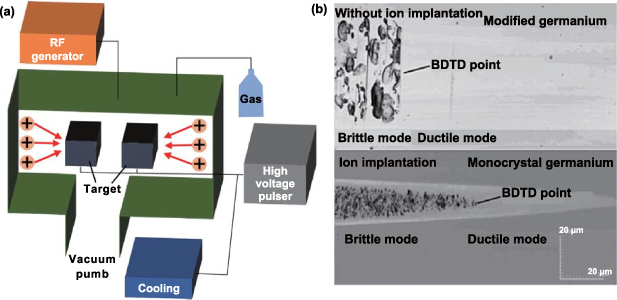
Figure 18. Schematic illustration of PSII ion implantation device and its processing effect. (a) PSII ion implantation device, (b) the critical cutting thickness of single crystal germanium after ion implantation. Reprinted from [174], Copyright © 2014 Elsevier Inc. All rights reserved.
Download figure:
Standard image High-resolution imageTo solve the problem of low efficiency for a thick modified layer due to a large injection dose, Wang et al [171] proposed a multi-implantation technology, as shown in figure 19. The channel effect induced by multi-ion implantation increases the implantation thickness by 169.35% under the same condition compared with the normal implantation. Therefore, a thicker modified layer can be obtained for brittle materials with a relatively small injection dose, further improving the DBT depth. To prove the prospect of multi-implantation in brittle material cutting, a micro-pillar array consisting of 270 orthogonal cylindrical slots was successfully fabricated on the modified Si. In addition to improving the machinability of the workpiece, ion implantation is also utilized in the modification of the diamond tool to restrain tool wear. Lee et al [175] modified the diamond tool by ion implantation using Ga as ion doping. The results indicated that the surface free energy of the diamond tool decreased after ion implantation, leading to a decrease of the reaction intensity between diamond and ferrous metal. The maximum wear width (VBmax) of the unmodified diamond tool is 12.75 μm, while the modified diamond tool only has wear in the flank face, with a VBmax of 7.5 μm.
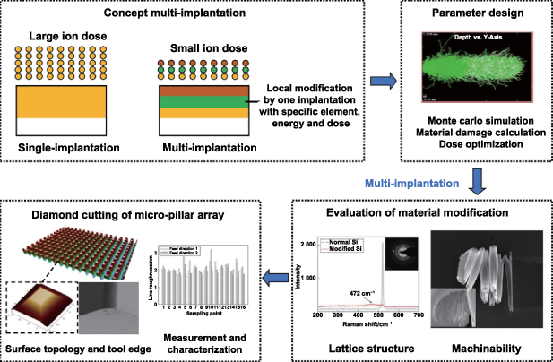
Figure 19. Multi-implantation assisted microstructure preparation process. Reprinted from [171], © 2018 Published by Elsevier Ltd.
Download figure:
Standard image High-resolution imageAt present, researchers have conducted intensive studies on the removal mechanism of IIAC, and have made more achievements in machinability improvement and tool wear suppression. However, IIAC is generally suitable for non-metallic crystals, and the materials available are limited. Because it is difficult to completely remove the modified layer during the machining process, it is difficult to apply it to the occasions sensitive to the change of lattice structure.
3.4.3. Other thermal assisted cutting.
The basic principle of TAC is to heat the surface of the workpiece to improve the machinability of DMMs. In addition to the laser as an external heat source, there are electromagnetic induction [176, 177], gas torch [31], heating with furnace [178], and others. Electromagnetic induction heating uses a coil through high-frequency current electromagnetic induction heating workpiece or tool. Baili et al [176] designed an induction heating workpiece processing system and carried out cutting experiments on titanium alloys. It is found that when the temperature is raised to 750°, the cutting force reduction amplitude can reach 34%, and the roughness Ra of the machined surface is significantly reduced by about 50%. Kizaki et al [177] studied the cutting of zirconia ceramics with induction heating tool, as shown in figure 20. When the tool temperature is heated to 500°, the cutting force is reduced by more than 50%, the cracks on the machined surface are significantly suppressed, and the tool edge has almost no wear. Maity and Swain [179] conducted cutting research on high manganese steel by burning a mixture of natural gas and oxygen to preheat the workpiece. It is found that increasing the workpiece temperature can significantly improve the tool life, but a higher temperature will affect the recrystallization process of the workpiece and limit the improvement of machining quality. Parida and Maity [180] used the same method to study the cutting of titanium alloys. It is found that the cutting force decreases significantly with the increase of heating temperature, and the machining effect of Ti-5553 is better than that of Ti6Al4V. Bermingham et al [178] studied the tool wear mechanism of high-speed cutting titanium alloys by heating the workpiece with a preheating furnace. They found that although TAC reduces the cutting force, it has a harmful effect on tool life. Proper cooling technology can prolong tool life. Although the above-mentioned TAC technology can significantly reduce the cutting force and improve the machinability of the workpiece, it is difficult to achieve precise control of the heat-affected range, which limits the improvement of the machining accuracy of the workpiece.

Figure 20. Principle, device and machining effect of induction heating tool. Reprinted from [177], Copyright © 2014 CIRP. Published by Elsevier Ltd. All rights reserved. (a) Schematic diagram of heating principle and device. (b) Cutting forces and machined groove surfaces.
Download figure:
Standard image High-resolution image3.5. Hybrid field-assisted cutting technology
As described above, single field assistance can effectively improve cutting performance. Furthermore, when different fields are combined to assist cutting, the coupling of the different technologies would result in unexpected benefits in terms of machinability. However, there is little research on HFAC technology so far. It is a promising development direction in the ultra-precision cutting field and deserves more attention. Several main technologies of HFAC were introduced in this section.
3.5.1. Laser & ultrasonic vibration assisted cutting.
LAC can reduce the hardness and improve the ductility of the workpiece with laser heating. UVC can reduce the cutting forces and inhibit tool wear. The technology combining laser and ultrasonic vibration assisted cutting can further improve the machinability of DMMs and achieve a better machining quality. Jiao et al [14, 181, 182] applied laser and ultrasonic vibration hybrid assisted cutting technology to machine WC. It was demonstrated that, with the hybrid field assistance, the machining dimension precision was improved by 65%, the tool flank wear was effectively reduced by 45%, and the thrust force was reduced by 60%. Kim et al [183] applied the hybrid machining method to cutting SiCp/Al composites. The results indicated that the average cutting force was significantly reduced by 61%, compared with LAC. The surface roughness was decreased by about 45% in Sa, compared with OC.
Peng et al [184] further explored the cutting mechanism of SiCp/Al composites and the suppression mechanism of subsurface damages using the HFAC technique, as shown in figure 21. The results demonstrated that small particle fragmentation and particle compaction were the main material removal forms, which presented an excellent plastic removal process. The hybrid machining technology could effectively inhibit subsurface damage. Molecular dynamics simulation in the in-situ laser and vibration hybrid assisted cutting of single crystal silicon have been carried out by Liu et al [185] through a modified molecular dynamics model, as shown in figure 22. They found that the introduction of the thermal field further reduced the cutting force based on UVC, and the thermal field could suppress the pull-off and cracking generated in UVC. However, the amorphous layer flow caused by the thermal field and the pulling effect caused by the tool vibration can cause the rotation of the grains, resulting in the degradation of the surface quality, and the process parameters should be optimized to avoid this phenomenon in practice.

Figure 21. Schematic of laser and ultrasonic hybrid assisted cutting principle and equipment. (a) Cutting mechanism. (b) Experimental setup. Reprinted from [184], © 2022 Elsevier Ltd and Techna Group S.r.l. All rights reserved.
Download figure:
Standard image High-resolution image
Figure 22. Molecular dynamics simulation in laser and ultrasonic hybrid assisted cutting process of silicon. Reproduced from [185]. CC BY 4.0. (a) Material deformation morphology and atomic flow state at room temperature (300 K). (b) Material deformation morphology and atomic flow state at 1 200 K.
Download figure:
Standard image High-resolution image3.5.2. Ultrasonic vibration & magnetic field assisted cutting.
To solve the problems of surface damage and side burr generated in UVC of titanium alloys, Yip et al [15] introduced a magnetic field (see figure 23). In UVC, the recovered materials were superimposed on individual recovered areas, creating visible vibration scars on the machined surface. During a single cutting cycle of UVC, the magnetic field inhibits material recovery by controlling the migration of magnetic particles toward the bottom surface of the workpiece to form metal chains. They demonstrated that significant suppression of material swelling and cutting scar area aggravated by tool vibration under the effect of magnetic field. Moreover, the error percentages of width groove and depth were decreased to 1.77% and 1.69%.
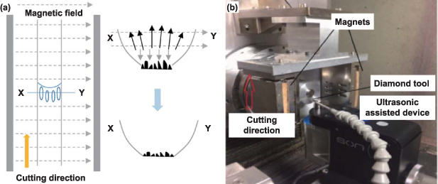
Figure 23. Schematic of vibration and magnetic field hybrid assisted cutting principle and equipment. (a) Cutting mechanism. (b) Experimental setup. Reprinted from [15], © 2021 The Society of Manufacturing Engineers. Published by Elsevier Ltd. All rights reserved.
Download figure:
Standard image High-resolution image3.5.3. Cold plasma & ultrasonic vibration assisted cutting.
To suppress diamond tool wear in cutting ferrous metals, Huang et al [13] developed an ultrasonic vibration-assisted cutting devices with cold plasma, as illustrated in figure 24. The real-time cooling was achieved using cold nitrogen plasma as the cutting medium, which could also inhibit diamond graphitization. Periodically interrupted cutting was achieved by driving the diamond tool with an ultrasonic elliptical vibrator during the cutting process. The cyclical change of tool position and cutting force results in reducing the tool wear by decreasing the cutting temperature. Real-time utilization of nitrogen cold plasma jet can adjust the properties of the workpiece surface and facilitate the entry of cold plasma jet into the cutting area during ultrasonic vibration assisted cutting of ferrous metals. The results indicated that the flank wear of HFAC was less than 50% of OC. Tang et al [186] proposed that the application of cold plasma and ultrasonic elliptic vibration assistance resulted in a decrease in cutting temperature and surface roughness. Compared with dry cutting, the diffusion wear was significantly reduced by 70.37%.

Figure 24. Schematic of cold plasma and ultrasonic vibration hybrid assisted cutting device. Reproduced from [13], with permission from Springer Nature.
Download figure:
Standard image High-resolution image3.5.4. Ultrasonic vibration & thermal field assisted cutting.
Sofuoğlu et al [187] introduced a new hybrid cutting technology that combines an ultrasonic vibration system with a hot furnace, as illustrated in figure 25. The furnace was used to heat the workpiece to a specific temperature below the recrystallization temperature, effectively softening it. This novel technology capitalized on the machining characteristics of both methods of machining. The stable cutting depth was increased by 22% with the hybrid field assistance, as compared to UVC. Compared to OC, there was a 40% reduction in surface roughness. However, the method caused higher cutting temperatures, which could reduce tool life. Muhammad et al [37] employed a resistance heater in the form of a band to encase and heat a titanium alloy. It was revealed that the HFAC can enhance the surface quality and decrease the cutting forces. Compared with OC, when the workpiece was heated to 300 °C and the DoC was 0.3 mm, the cutting force of Fx and Fy decreased by 83.2% and 84.7%, respectively. In addition, the maximum drop in surface roughness Ra can reach 62%.

Figure 25. Schematic of vibration and thermal field assisted cutting. (a) Experimental setup. (b) Detailed principle. Reproduced from [187], with permission from Springer Nature.
Download figure:
Standard image High-resolution imageTo sum up, in order to break through the limitation of conventional ultra-precision machining technology, researchers have proposed FAC technology based on laser, ultrasonic vibration, magnetic field, plasma and other related fields. It can be seen from figure 26 that the various significant developments in FAC and the burgeoning material processing applications have proven their convenience and usefulness.

Figure 26. The main challenges and progress of the FAC in surface quality.
Download figure:
Standard image High-resolution imageThe energy field acts on the cutting area to improve the machinability of DMMs, which can effectively reduce the cutting force, reduce tool wear and subsurface damage of the workpiece, and achieve the purpose of increasing tool life and improving the machining quality of DMMs components. However, there still exist a few challenges in the FAC technology: (1) due to the introduction of tool vibration, laser heating, magnetic field modification and other effects in FAC, material deformation and removal is a multi-field coupling process that integrates elastoplastic mechanics, microscopic heat transfer, material mechanics and tribology. At present, there is a lack of in-depth research on the formation mechanism of high-precision and low-damage surface of DMMs under the assistance of the energy field, especially the lack of research on the surface damage suppression of workpiece and tool wear inhibition mechanism, which affects the further improvement of the manufacturing level of DMMs components. (2) HFAC can significantly improve the machinability of DMMs. However, the equipment compatibility of multi-fields is the issue restricting the development of the HFAC technology. And the material removal mechanism under the hybrid fields still needs to be researched further. For future studies, to obtain the best possible results in terms of high-quality surface generation, the multi-FAC system, which is easy to operate and integrate needs to be urgently developed.
4. Field-assisted surface quality improvement methods
Compared with OC, FAC can achieve better forming accuracy and lower surface/subsurface damage, but it is not the final process of high-precision DMMs components, because the mechanical processing will inevitably introduce scratches, cutting texture, damaged residue, and other defects on the machined surface [21, 22]. On the other hand, the motion trajectory of the ultra-precision machine tool determines the forming accuracy of the components and limits the improvement of accuracy. Deterministic polishing is usually used as the final finishing method to obtain the desired surface quality. But the traditional polishing process has low convergence efficiency, poor long-term stability of removal function, edge effect, and large-scale machining errors [23]. In order to enhance the production efficiency and precision of DMMs components, various research institutions have put forward the non-contact field-assisted surface quality improvement methods such as LMP, MFAP, IBF, and APP. Field-assisted surface quality improvement methods are the subsequent surface treatment process of FAC. By virtue of the gain effect of the energy field on the machining process, the machined surface by FAC can be post-processed to achieve sub-nanometer accuracy and almost damage-free surface and subsurface. In this section, the types, principles, and equipment of these methods are summarized in detail.
4.1. Laser melting polishing technology
4.1.1. Principle of LMP.
LMP is a polishing method that uses laser irradiation to reshape the surface topography by melting or peeling [188], so as to obtain a desired surface without cracks or defects. Therefore, the polishing principles can be divided into surface melting polishing and removal polishing according to the interaction between laser and materials.
LMP takes advantage of the photothermal effect of laser. When the temperature of the material irradiated by the laser rises above the melting point, the fused material will flow to the depression or crack, forming a flatter surface after solidification. Ramos et al [189] divided melting polishing into the following two types according to melting depth: surface shadow melting (SSM) and surface over melting (SOM). The surface topography can be regarded as a combination of several peaks and valleys. When the laser irradiates on the rough surface, peak is most likely to have significant melting first. In the SSM state, the melting depth is less than the height of peak. The fused material flows from peak to valley under the effect of gravity, surface tension and thermocapillary force, thus reducing peak-to-valley (PV) and surface roughness. On the contrary, the melting depth of SOM is larger than PV, and the surface layer is completely melted, i.e. 'over melted'. A strong SOM will also be accompanied by a ripple structure formed on the solidified surface by the Marangoni effect. Ramos et al [190, 191] found that with the increase in laser energy density, there will be a transition from SSM to SOM. It is worth mentioning that no one is between SSM and SOM. For some rough surfaces, a suitable SOM will not only not bring ripple, but also achieve a smoother effect than SSM. And even if ripples are formed, as long as the PV is lower than the original surface, the polishing effect can be achieved [192].
4.1.2. Types and machining characteristics of LMP
4.1.2.1. Types of LMP.
The concept of LMP first appeared in the 1980s [24], and was initially applied to the surface treatment of fused silica. It eliminates microcracks and improves the energy threshold by laser melting. But in fact, the technology of improving surface quality by laser melting has appeared earlier [193]. After decades of development, LMP has been widely applied in the surface treatment of metals [194, 195], alloys [196, 197], glasses [198–200], ceramics [201], and other materials (table 5), and has become a new polishing technology and shine in semiconductor, optoelectronics, aerospace and other fields [202–204]. Depending on the initial roughness and spatial wavelength, different kinds of lasers should be selected for polishing.
Table 5. Summary of typical LMP literature.
| Researchers | Types | Materials | Initial roughness/μm | Roughness after LMP/μm | Processing time/(cm2·min−1) |
|---|---|---|---|---|---|
| Ostholt et al [206] | CWLP | GGG40 | 1.7 | 0.4 | 1 |
| Temmler et al [195] | A1S1 H11 | 0.53 | 0.05 | 15 | |
| Chen et al [207] | 316L | 4.84 | 0.65 | 12 | |
| Marimuthu et al [208] | Ti6Al4V | 10.2 | 2.4 | 3.75 | |
| Tian et al [209] | Ti6Al4V | 21.46 | 0.51 | 1.2 | |
| Zhang et al [210] | Ti6Al4V | 8.79 | 3.34 | 300 | |
| 316L | 14.52 | 3.86 | |||
| IN718 | 15.28 | 2.76 | |||
| El Hassanin et al [211] | AlSi10Mg | 21.5 | 7.53 | 1.02 | |
| Xu et al [212] | TiAl | 16.06 | 4.74 | 96 | |
| Ukar et al [190] | PLP | DIN1.2379 | 5.32 | 0.8 | 7.68 |
| Ma et al [213] | TC4 | 5.226 | 0.375 | 5.28 | |
| TC11 | 7.21 | 0.73 | |||
| Chang et al [214] | SKD61 | 0.285 | 0.155 | 9.12 | |
| Li et al [215] | MB26 | 0.525 | 0.166 | 5.28 | |
| AZ80 | 0.515 | 0.308 | |||
| Brenner et al [216] | 1.2738 steel | 0.41 | 0.21 | 12.15 | |
| Li et al [217] | IN 718 | 10 | 0.1 | 6.9 | |
| Zhang and Chen [218] | Al/PLA | 23.27 | 3.11 | 24 | |
| Niitsu et al [219] | Si | 131.3 nm | 19.6 nm | 0.144 | |
| Xiao et al [220] | Si | 1.2 nm | 0.6 nm | 24 |
In the continuous wave laser polishing (CWLP) (figure 27(a)), lasers with powers of 100–300 W scan the material surface at velocities of 10–200 s·cm−2 [221] to form a continuous melted layer along the scanning direction, usually with a depth of 20–100 μm [195]. With the movement of laser beams, new molten materials are continuously added and solidified on the opposite side of the molten pool. The melting process is only influenced by the laser power, spot diameter, and scanning velocity. Because of the flexibility of laser, it has unique advantages in polishing free surface. Ostholt et al [206] used a continuous wave laser to polish the freedom surface of an optical mold, and the roughness was reduced from 1.7 μm to 0.4 μm. Temmler et al [195] found that laser is helpful to grain refinement and hardness enhancement, and obtained the surface of tool steel with Ra = 50 nm. The improvement of the material's tensile strength and ductility after laser polishing was also found in further research [207]. CWLP is usually used to process rough surfaces with macro scale spatial wavelength and large-sized workpieces, such as selective laser melting parts [209, 222], it may not be suitable for micro scale element or structure [220].
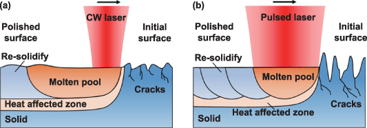
Figure 27. Schematic diagram of LMP principle. Reproduced with permission from [205]. Rights Managed by the Laser Institute of America. (a) Continuous wave laser polishing. (b) Pulsed laser polishing.
Download figure:
Standard image High-resolution imageIn contrast to CWLP, the melting process of pulsed laser polishing (PLP) is discrete (figure 27(b)). Due to the extremely tiny beam diameter (<100 μm [214]) and tens of microseconds pulse duration [200], the existence time of laser formed micron molten pool (molten depth less than 6 μm [223]) is very short, and the fused material has solidified before the forming of next molten pool. For the spatial wavelength of initial surface roughness δ< 80 μm, CWLP has little effect [188], while PLP can further reduce the roughness to nano-scale [205]. Xiao et al [220] successfully eliminated the rainbow pattern on monocrystalline silicon by nanosecond pulsed laser, as shown in figure 28, which was produced by ultraprecision cutting, and reduced the roughness to 0.6 nm. Porosity can be reduced by laser melting, and Li et al [217] found that shrinkage cavities, pores, and microcracks in the heat affected zone of IN 718 superalloy was disappeared after PLP.
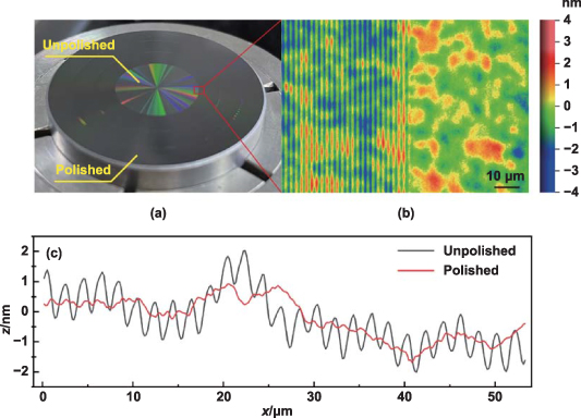
Figure 28. Laser polishing of monocrystalline silicon. (a) The rainbow pattern produced by ultra-precision cutting (inner circle) was vanished after laser polishing (outer ring). (b) Polishing boundary under White Light Interferometer. (c) Comparison of profile between original and polishing region. Reproduced from [220]. CC BY 3.0.
Download figure:
Standard image High-resolution imageIt is worth mentioning that although PLP can reduce the surface roughness to nano-scale, it does not mean that pulse is necessarily better than continuous wave, because PLP has almost no improvement in rough surface with δ > 80 μm. Therefore, it is particularly important to select the appropriate laser according to the specific conditions of the initial surface [188]. Generally, CWLP is SOM [208, 209, 211], accompanied by high frequency ripple. Interestingly, pulse laser has a very good polishing effect on high-frequency roughness, which naturally leads to dual-beam polishing technology [223]. The CW laser can be first used to remove the low frequency roughness. Followed by PLP, high frequency ripple introduced by SOM can be removed. Micro end milled Ti6Al4V with a surface roughness Sa of (172 ± 25) nm is polished to (47 ± 5) nm by this strategy. This process can also be refined into three laser beams [224]. Previous research has proved that proper SOM can lead to lower roughness compared with SSM, because properly increasing the melting pool duration is contributed to the full flattening of the melt bulk. As a result, dual-beam polishing technologies were developed to increase the duration of the molten pool [225, 226].
The LMP equipment is simple in structure and flexible in operation, and laser beam can be guided to the processing surface through optical fibers and mirrors (figure 29(a)) because of its long-distance transmission characteristics. The velocity and trajectory of the laser spot are controlled by the galvanometer (figure 29(b)), which can be set up by a computer together with the laser power and frequency. Laser system can be attached with displacement table, chamber, etc to form an independent polishing system (figure 29(c)), or integrated with machining equipment (robots, machine tools, etc) to satisfy various polishing requirements (figure 29(d)).
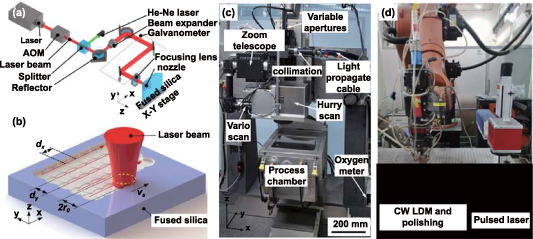
Figure 29. Schematic of LMP system and device. (a) Laser path system. Reproduced from [200]. © 2019 The Author(s). Published by IOP Publishing Ltd on behalf of the IMMT. CC BY 3.0. (b) Laser scanning beam by galvanometer. Reproduced from [200]. © 2019 The Author(s). Published by IOP Publishing Ltd on behalf of the IMMT. CC BY 3.0. (c) Laser polishing system. Reprinted from [195], © 2020 The Author(s). Published by Elsevier Ltd. Mounting on (d) robot arm. Reprinted from [212], © 2021 The Society of Manufacturing Engineers. Published by Elsevier Ltd. All rights reserved.
Download figure:
Standard image High-resolution image4.1.2.2. Machining characteristics of LMP.
For the micro scale melting pool in LMP, the surface flattening is mainly caused by surface tension and thermocapillary flow. Fluid tends to flow to the direction of high surface tension, i.e. thermocapillary or Marangoni flow [227, 228]. Temperature gradient is formed between the center and the edge of the molten pool because of the Gaussian energy distribution of laser beam. According to the positive and negative of the temperature gradient of surface tension ( ), the flow from edge to center or the opposite can occur [193, 229]. For most metal materials
  , which is why the boundary ripple occurs during SOM. But there are exceptions,
  at 2283 K for stainless steel, leading to center bulge or boundary ripple under different energy intensities [230].
The molten surface with roughness features, which owns higher surface tension because of their large curvature, oscillates as stationary capillary wave driven by surface tension and damps out due to the viscosity of molten bulk, forming a smoother surface. Therefore, two polishing regimes can be distinguished: thermocapillary regime and capillary regime, depending on the dominant drive, stationary capillary wave oscillations or Marangoni flow, as shown in figure 30.
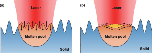
Figure 30. Mechanism of LMP. (a) Capillary regime, roughness features oscillate as stationary capillary wave and damp out, forming a smooth surface. (b) Thermocapillary regime, the thermophysical properties of materials determine whether the Marangoni flow is inward (dash arrow) or outward (solid arrow).
Download figure:
Standard image High-resolution imageThe LMP process is mainly determined by three factors: surface material properties, original surface topography, and laser energy fluence. In order to fully utilize the advantages of laser polishing, a relatively smooth surface will be prepared. The auxiliary gas, according to the material properties, can provide a more suitable environment for LMP [194, 197, 213]. The control of laser parameters is the most convenient and expeditious, so the precise control of energy density determines the quality of polishing. The energy density can be simply expressed as
where I is energy density, P is laser power, t is laser irritation duration per unit time and S is scanning area per unit time. The control of laser power can be implemented in the mode [212, 231], size [190, 214, 232, 233] and distribution [196]. Continuous laser can be modulated into pulse laser by Q-switch or mode locking [212]. Power has a positive contribution to the depth and diameter of the molten pool [234, 235]. As mentioned above, increasing power can observe the transition from SSM to SOM [190, 191], and the effect of Marangoni flow will gradually become obvious [229].
For continuous laser, the working time t is the unit time, and S= vtD, where v is the scanning velocity, and D is the beam diameter (1/e2). As for pulsed laser, t can be written as τ/f, where τ is pulse width, f frequency. The scanning area of each pulse can be expressed as πD2/4, while S is related to the overlap rate between pulses, which can be expressed as
where  is the overlap rate of the scanning direction,
  is the overlap rate perpendicular to the scanning direction, and D can be simply adjusted by the defocusing amount. Therebefore, S and t are not variables that can be considered separately in pulse laser polishing, and scanning area per unit time S/t considering pulse width, frequency, laser diameter, scanning velocity and pitch can be separated from the equation (20). Phefferkorn et al [223, 229, 232] systematically explored the effect of pulse width on surface topography, and found that long pulse width can form larger molten pool, which can reduce low-frequency roughness better. Because of the longer duration of larger molten pool, if the laser frequency is further increased until the pulse interval is less than molten pool duration, the continuous melting process will become a quasi-continuous melting process [205]. Laser diameter decreases with the increase of defocus amount [203, 235, 236]. When focus energy intensity is too much, a certain amount of defocusing will greatly help to reduce the surface roughness. Xiao et al [220] got a monocrystalline silicon surface with a surface roughness Sa as low as 0.6 nm by defocusing 0.8 mm. Better choices of scanning velocity [199, 211, 218, 237] and scanning pitch [237] can not only obtain smaller surface roughness, but also improve the surface quality. The highest hardness of 316 l stainless steel could be obtained after three passes with 100 mm·s−1 scanning velocity [207].
4.2. Magnetic field assisted polishing technology
4.2.1. Principle of MFAP.
Magnetic field assisted polishing (MFAP) is an interdisciplinary technology, which involves electromagnetics, fluid dynamics, solid mechanics, chemistry, and other related fields [25]. According to the different tools used, MFAP can generally be divided into two categories: one is the magnetic abrasive finishing (MAF) technology using magnetic abrasive particles, and the other is the magnetorheological finishing (MRF) technology using non-magnetic abrasive particles, as shown in figure 31. MAF directly acts on the magnetic abrasive through the external magnetic field, resulting in complex relative motion between the workpiece and the abrasive particle. The magnetic abrasive produces contact scratching, extrusion and cutting effects on the workpiece surface, so as to improve the surface integrity of the workpiece [238]. MRF mainly acts on the magnetorheological liquid (MRL) through the magnetic field, and then acts on the non-magnetic abrasive to realize the finishing process. The principle is as follows: under the action of gradient magnetic field, the MRL will form a solid-like structure with higher yield strength, and the non-magnetic particles will form a flexible polishing tool by the solidification of MRL to achieve the micro removal of the surface [239].
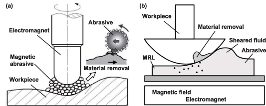
Figure 31. The principle of MFAP. (a) The material removal mechanism of MAF. Reprinted from [240], Copyright © 2003 Elsevier Science B.V. All rights reserved. (b) The material removal mechanism of MRF.
Download figure:
Standard image High-resolution imageThe advantages of MFAP technology are summarized as follows [30]: (1) MFAP is a non-contact polishing technology, with no subsurface damage layer. (2) MFAP is a kind of controllable machining technology. The distribution and motion of polishing particles can be changed by adjusting the magnetic field. (3) MFAP is a stable machining technology. In actual processing, the polishing particles can achieve self-sharpening, so there is no wear of the polishing head, and the removal function is stable.
4.2.2. Types and machining characteristics of MFAP
4.2.2.1. Magnetic abrasive finishing.
MAF is a flexible processing method that is not limited by the size and shape of the workpiece. It was originally developed as a machining process in the Soviet Union in the 1930s, but it was not further developed until after the 1960s [241]. In recent years, researchers have gradually designed MAFs in various forms such as cylinders, planes, and curved surfaces. Shinmura et al [28] performed the cylindrical MAF to finish the Si3N4 ceramic rod with a diameter of 2 mm. The workpiece is held between the N pole and the S pole of the magnet, and the working gap between the workpiece and the magnet is filled with magnetic abrasives. The abrasive abrasives form a flexible magnetic abrasive brush (FMAB) under the action of a magnetic field, which acts as a multi-point cutting tool. Surface roughness Ra increased from 0.45 μm to 0.04 μm after processing. Chang et al [242] conducted an experimental study on SKD11 by using the cylindrical MAF (see figure 32(a)), and the surface roughness Ra was increased from 0.25 μm to 0.05 μm after finishing. Yamaguchi and Shinmura [243] reported internal finishing of alumina ceramic components using a working rotary system. Four small permanent magnetic poles are evenly arranged on the circular yoke to generate the magnetic field required to attract iron particles to gather on the inner surface of the tube. As the tube rotates at high speed, the abrasives in the mixture perform micro-cut the inner surface of the tube. After processing, the surface roughness of alumina ceramics decreased to Ra 0.02 μm, and the residual stress was significantly reduced. Kim et al [244] used MAF to finish the planar workpiece of aluminum matrix composite. A plane MAF consists of a single permanent magnet that generates a gradient magnetic field and achieves material removal by regulating rotational and translational motion. After 60 min of processing, the surface roughness reaches Ra 0.35 μm.
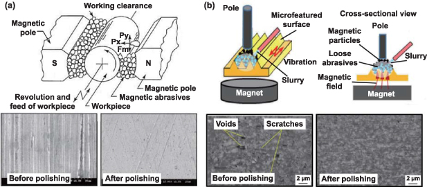
Figure 32. The principle and machining results of MAF. (a) Cylindrical MAF. Reprinted from [242], Copyright © 2002 Elsevier Science Ltd. All rights reserved. (b) Localized VAMAP. Reproduced from [36]. CC BY 4.0.
Download figure:
Standard image High-resolution imageIn addition, based on the MAF principle, the researchers found that additional ultrasonic vibrations can be used to obtain a perfectly quality workpiece surface. Yin and Shinmura [32] proposed a vertical vibration-assisted magnetic abrasive finishing (VMAF) technique, in which the workpiece was vibrated in the vertical direction. The relative motion between the FMAB and the workpiece, consisting of vertical vibration and rotation, can generate pulse pressure acting on the abrasive particles to achieve efficient micro-removal of materials. They applied this method to the finishing of stainless steel and found that the vibration-assisted deburring time was reduced by 40% compared with no vibration, and the initial surface of 2.5 μm Ry pre-polish was improved to 0.45 μm Ry after four passes of polishing. Further, Guo et al [245] proposed a vibration-assisted magnetic abrasive polishing (VAMAP) method, which could polish micro-featured surfaces. The surface roughness Ra increased from 166.9 nm to 25.4 nm and from 2.23 μm to 0.32 μm when the rectangular microstructure and the miniature V-grooves were polished, respectively. And the profile of microstructures was well maintained. However, this technique is limited to nonmagnetic or micromagnetic materials with straight microfeatures. On this basis, Guo et al [36] presented a new localized VAMAP method, as shown in figure 32(b). It can be used to polish curved microfeatures, and the workpiece material can be ferromagnetic. This method uses loose abrasives to achieve nanoscale surface roughness and damage-free surface while maintaining the morphology of the microfeatures. Using this method to polish the Fresnel-type structure, the surface roughness Ra was reduced from the initial value of 10.4 nm to 7.7 nm.
4.2.2.2. Magnetorheological finishing.
At present, there are various types of MRF devices, such as groove type [25], wheel type [25], belt type [246, 247], disk type [248, 249], cluster type [250, 251], ball head type [252, 253], etc, which are suitable for surface processing of various types and sizes, such as plane, concave, convex, inner surface, etc. The diameter of the polished workpiece is mostly more than 100 mm or even 1 m. The research status and characteristics comparison of MRF devices are shown in table 6.
Table 6. The research status and characteristics comparison of MRF device.
| Researcher | Representative structure | Main features | Material & processing quality | Deficiencies |
|---|---|---|---|---|
| Kordonski et al [25] | Groove type | Convex workpiece | Optical glass | Not suitable for the processing of small diameter concave structure workpieces |
| Ra ≦ 40 nm | ||||
| Kordonski et al [25], Kim et al [254] and Hong et al [260] | Wheel type | Flat and convex workpieces | BK7 glass | |
| Ra = 3.80 nm. | ||||
| 3Y-TZP/Al2O3, | ||||
| Ra = 1.96 nm | ||||
| Ren et al [246] | Belt type | Large size workpiece, high efficiency | BK7 glass | |
| RMS = 4.72 nm | ||||
| Pan et al [251] and Wang et al [259] | Disk type | Single crystal Si | ||
| Ra = 2.40 nm. | ||||
| K9 glass | ||||
| Ra = 1 nm | ||||
| Singh et al [252] and Bedi et al [253] | Ball head type | Free form surface workpiece | Fused silica | Complex structure and high assembly requirements |
| Ra = 0.15 nm. | ||||
| Gray cast iron | ||||
| Ra = 83 nm | ||||
| Yin et al [255] | Oblique axis type | Small curvature aspheric workpiece | Stainless steel | The circulation and renewal of MRPF are not fully considered |
| Ra = 20 nm | ||||
| Zhang et al [256] and Zhai et al [257] | Ultrasonic vibration | Axial vibration of the polishing head | K9 glass | Increase MRR by more than three times |
| Ra = 4 nm | ||||
| Sapphire | ||||
| Ra = 0.442 nm | ||||
| Yan et al [258] | Electrochemical | Electrochemical controlled etching | GaN | Synergistic effect of chemical etching and mechanical flexible removal |
| Ra = 0.9 nm |
The MRF technology was first proposed by William Kordonski, who developed the first MRF device in 1990s [25]. However, the first groove type MRF device is limited to polishing convex surfaces. William Kordonski creatively proposed a wheel type MRF device, as shown in figure 33(a) [25]. In the device, an electromagnet was used at the polishing tool to excite the gradient magnetic field, and the MRL was injected at the front end of the polishing tool. When the polishing tool rotates, it drives the MRL into the polishing area with magnetic field distribution. According to the rheological characteristics of the MRL, the MRL hardens rapidly and can be used to polish the workpiece surface. Kim et al [254] carried out research based on wheel type MRF device, and adjusted the distribution position of the polishing wheel and workpiece from vertical direction to horizontal direction. Four kinds of alumina abrasive polishing solutions with different compositions and proportions were prepared to study the surface topography and roughness obtained under different processing parameter settings such as electric current and wheel velocity. After optimizing the process parameters, it was found that the surface roughness of BK7 glass could be reduced to 3.8 nm. Yin et al [248, 249] explored the material removal rate under the influence of permanent magnet configurations by using a disc type MRF device, as depicted in figure 33(b). Permanent magnets of different configurations are placed under the polishing disc and form a gradient magnetic field distribution. The configured MRL fills the gap between the workpiece surface to be polished and the underneath of the polishing disc. A porous pad is used at the bottom of the polishing disc to increase the friction between the MRL and the disc, and the MRL is adsorbed to form a polishing die for processing. They obtained the results that the surface roughness of zirconia ceramic decreased from the original value of about 100 nm to less than 20 nm.
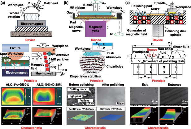
Figure 33. Types and characteristics of MRF, (a) wheel type. Reproduced from [254]. CC BY 4.0. (b) Disk type. Reprinted from [249], © 2018 Elsevier B.V. All rights reserved. Reprinted from [259], Copyright © 2014 Elsevier Inc. All rights reserved. And (c) cluster type.Reproduced from [250], with permission from Springer Nature. Reproduced from [251], with permission from Springer Nature.
Download figure:
Standard image High-resolution imagePan and Yan [250] expanded the disk magnetorheological field excited by a single permanent magnet to the cluster magnetorheological field distributed around the circumference of multiple permanent magnets, realizing the plane polishing of three kinds of hard and brittle material substrates with a diameter of about 100 mm. On this basis, they further improved the experimental device and developed a dynamic magnetic field cluster MRF device [251], as shown in figure 33(c). The deflection movement occurs in a small local range, forming a dynamic magnetic field. This method is conducive to achieving the self-sharpening of polishing particles in MRF, and obtaining a stable material removal function. In the device of literature [250], the position of the permanent magnet is fixed, so a static gradient magnetic field distribution is formed. In the device of literature [251], the permanent magnet is no longer in a fixed position, and a partial sway motion occurs in a small range, to form a dynamic magnetic field. In the annular array of permanent magnets under the polishing disc, the permanent magnets are embedded on the small eccentric shaft. The main shaft of the polishing disc rotates around the fixed axis, and the eccentric main shaft rotates to drive the eccentric rotation of the deflection disc, thus driving the small eccentric shaft and the embedded permanent magnet to rotate together. Since the spatial position of the rotating main shaft of the polishing disc and the rotating main shaft of the permanent magnet is offset, a dynamic magnetic field is formed. This method is conducive to achieving the self-sharpening of polishing particles in MRF, and obtaining a stable material removal function. The device is used to polish the single crystal silicon plane. After 5 h, the surface roughness is reduced from the initial 480 nm to 3.3 nm, and an ultra-smooth surface is obtained.
Compared with the disk type and cluster type MRF devices that are only suitable for processing plane workpieces, the oblique axis type and ball head type MRF devices are more flexible and suitable for processing complex surfaces. Yin et al [255] used an oblique axis MRF device to polish the stainless steel workpiece surface. When the MRL moves between strong and weak magnetic fields, it can realize fast switching between liquid and solid like states. After polishing, the surface roughness decreases from the original 450 nm to 20 nm. Singh et al [252] used a MRF device to polish the inner surface of cylindrical gray cast iron. After 90 min processing time, the surface roughness Ra, Rq, and Rz values decreased by 77.44%, 70.16% and 72.16% respectively. In addition, Zhang et al [256] introduced axial ultrasonic vibration into the MRF polishing head, and proposed an ultrasound-assisted magnetorheological polishing (UAMRF) method, which could further improve the MRR of MRF when applied to K9 glass. The MRR was about 3.1 times that of traditional MRF, and the surface roughness reached 4 nm. Zhai et al [257] used Fe3O4/SiO2 core-shell abrasives for UAMRF of sapphire wafers, which can achieve large MRR (1.974 μm·h−1) and low surface roughness Ra (0.442 nm). Another innovative idea of MRF is to introduce electrochemical action into the MRF process. Yan et al [258] proposed an electrochemical MRF (EC-MRF) technique combining a controlled electrochemical method and MRF. They took gallium nitride as the research object, controlled the surface processing quality by adjusting the etching potential difference, achieved a 113% increase in MRR compared to traditional MRF, and reduced the surface roughness from Ra 6.5 nm to Ra 0.9 nm.
4.3. Ion beam figuring technology
4.3.1. Principle of IBF.
IBF is a precision machining technology proposed and developed by Townsend [261]. Ion beam polishing technology has the advantages of high processing accuracy, good stability, non-contact processing, and fewer impurities compared with traditional polishing methods [262, 263]. The principle is that the ion beam with a certain amount of energy bombards the workpiece surface, and then continuously collides with the atoms inside the shallow optical surface for energy exchange, and the atoms with energy input continue to transfer energy to the surrounding atoms, forming a cascade motion. When the energy gained by the collision is large enough for the atoms to break free from the surface, they will detach from the solid surface to form sputtered atoms, thus achieving atomic-level material removal. The working principle is drawn in figure 34.
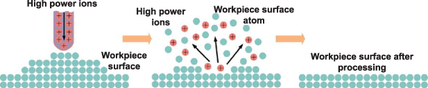
Figure 34. Principle of ion beam figuring.
Download figure:
Standard image High-resolution image4.3.2. Types and machining characteristics of IBF.
The types of IBF can be divided into the following three parts: (1) high power IBF (HPIBF), high-energy ion beam with an energy density of 107–108 W·cm−2 and 100 keV particle energy rapidly melts the workpiece surface to form the liquid phase. The surface liquid phase is driven by surface tension to flow to the low-lying areas of the surface, and finally a flat surface is obtained for polishing purposes. (2) Low energy IBF (LEIBF), the kinetic energy is transferred by the elastic collision between the incident ions and the nuclei of the surface layer, and the surface atoms are empowered to sputter out of the workpiece. Compared with HPIBF, the temperature increase of the workpiece surface during the polishing process is less than 400 K [4]. (3) Reactive IBF (RIBF), based on IBF, the inert work gas in the ion source is replaced by a reaction gas formed by one gas or a mixture of gases, combining physical and chemical action for material removal. Physical and chemical interactions reinforce each other and can increase the material removal efficiency to a greater extent [264].
At present, scholars carry out relevant research on various aspects such as material removal mechanism, process parameter optimization and figuring equipment development in IBF technology. Yuan et al [265] proposed an ion beam large interval cross-polishing process by optimizing the ion beam dwell time function for the thermal effect phenomenon in ion beam polishing. The temperature peaks and thermal stresses during polishing are reduced, and a high-quality surface of 0.040 λ (25.312 nm) PV was obtained. Li et al [266] studied the incidence angle of ion beam based on the obliquely incident IBF (OI-IBF) [267] process, and conducted experiments, the results are shown in figures 35(a)–(d). The results show that the surface error decreases from the original values of PV 1.986 λ and RMS 0.438 λ to PV 0.215 λ and RMS 0.035 λ after three iterations using the OI-IBF process. The experimental results demonstrate the feasibility of OI-IBF for KDP crystal polishing. Li et al [268] proposed a removal function model for IBF based on the relationship between the ion beam current density distribution parameters and the removal function. IBF experiments were conducted on fused silica. Experiment results show that the offline computation time of the removal function is reduced from 2 h to 5 min, the PV value of the initial surface topography error of the workpiece is reduced from 500 nm to 15 nm, and the RMS value is decreased from greater than 120 nm to less than 1.5 nm. Zhang et al [269] studied the material removal characteristics of RIBF of optical mirrors and carried out a comparative test between RIBF and IBF. The experimental results indicate that the RIBF process has good isotropy, and can significantly improve the material removal rate and reduce surface roughness. At certain process parameters, the RIBF process improved the volumetric removal rate by 22.5% compared to IBF, as shown in figures 35(e)–(f).
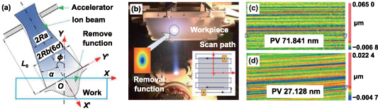
Figure 35. The principle and machining results of OI-IBF [266] with permission from [266] © The optical Society. (a) Schematic diagram of IO-IBF. (b) Raster scan model in OI-IBF. (c) and (d) Are the effects before and after IO-IBF.
Download figure:
Standard image High-resolution imageThe development of figuring equipment is a fundamental engineering problem for IBF. To meet the needs of high-performance optical part machining, many research institutions have developed IBF equipment and related supporting processes in the past nearly two decades. The IOM Institute in Germany has developed an IBF device, As shown in figure 36. The device controls the main performance index of the ion beam by changing the grid design, using an ion diaphragm, and optimizing the processing parameters to meet the demand for long-time stability of the ion source. The machining accuracy of optical devices is improved to 0.9 nm RMS by using 0.5 mm beam diameter ion beam [270].

Figure 36. Ion beam figuring equipment and tools. [270]. John Wiley & Sons. Copyright © 2007 WILEY‐VCH Verlag GmbH & Co. KGaA, Weinheim. (a) Ion beam figuring plant UPFA1, (b) material removal function under different beam diameters.
Download figure:
Standard image High-resolution image4.4. Atmosphere plasma processing technology
4.4.1. Principle of APP.
As for APP, material removal is realized by plasma etching. The plasma etching includes the following three processes: adsorption, reaction, and desorption [271] at atomic scale. And the etching processing is carried out by some chemically neutral active substances such as free radicals. The following are the basic surface reactions that are possible in plasma etching processes, as shown in figure 37. (1) Chemical etching (sputtering by ion bombardment); (2) physical sputtering (ion-assisted chemical reaction), including any other pure physical ion-related etching; (3) reactive ion etching (chemical etching and physical sputtering, (RIE)) [272]. Among them, RIE is the main process of APP.
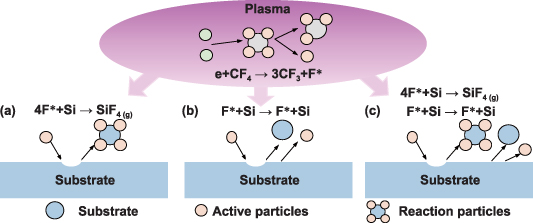
Figure 37. Surface etching process by plasma (take silicon, for example). (a) Chemical etching; (b) physical sputtering; (c) reactive ion etching.
Download figure:
Standard image High-resolution image4.4.2. Types and machining characteristics of APP.
Inductively coupled plasma (ICP) and capacitive coupled plasma (CCP) are commonly used in plasma processing [273], the schematic of the APP device is depicted in figure 38. The CCP generation mechanism is that radio frequency (RF) powers are applied to the top and bottom two opposite electrodes at the same time, or only to the bottom electrode, and the reaction gas vibrates in the electric field to generate plasma. ICP generator generates electromagnetic field by using RF current in an induction coil to accelerate electrons in torch and generate plasma to remove surface materials [274]. The induction coil consists of two coaxial quartz tubes with a quartz torch fixed in the center; the ignition and reaction gases are supplied through the inner tube. With the cooperation of the above components, the plasma can be generated in the quartz torch. As for ICP, the biggest advantage is that it is not polluted by electrode materials.
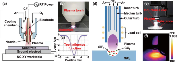
Figure 38. Schematic diagram of CCP. Reprinted from [275], © 2020 Elsevier Inc. All rights reserved. And ICP Reprinted from [276], © 2020 The Society of Manufacturing Engineers. Published by Elsevier Ltd. All rights reserved. (a) The principle of CCP. (b) Actual processing in CCP. (c) CCP tool influence function. (d) The principle of ICP. (e) Photo of ICP torch. (f) Temperature diagnostics of ICP.
Download figure:
Standard image High-resolution imageThe removal mechanism of plasma on surface materials is as follows: reactant gas is sent into the reaction chamber, electrons are collided and decomposed into active substances, and then these reactive free radicals diffuse to the substrate and react with the workpiece surface materials to generate volatile substances, so as to complete the nano removal of surface materials without causing sub surface damage. The plasma characteristics, plasma nozzle height, scanning speed and process gas composition play an important role in surface quality [277]. At the same time, adding oxygen to the plasma process gas can improve the material removal efficiency [278]. The chemical reaction between plasma active particles and workpiece is related to the surface temperature, so it is essential to analyze the effect of plasma discharge temperature on surface processing quality during processing. Ji et al [279] obtained the temperature field of the plasma by means of simulation analysis, and analyzed the nonlinearity between temperature and material removal rate, as shown in figure 39. Arnold et al [280] proposed a temperature coupling model, which improved the machining accuracy of free surface by means of finite element temperature distribution analysis and surface dwell algorithm. Su et al [281] established a method to calculate the residence time to suppress the nonlinear effect caused by the tool influence function caused by the temperature field.

Figure 39. Temperature field distribution simulation. Reprinted from [279], © 2019 Elsevier GmbH. All rights reserved. (a) The schematic diagram of heat transfer model; (b) the temperature field with different parameters.
Download figure:
Standard image High-resolution imageFor DMMs processed by plasma, atomic level smooth surface is obtained. Based on the layer-by-layer scanning dwell time solution strategy, Takino et al [282] used the CCP method to process the fused silica workpiece from 0.5 μm PV to 0.04 μm PV, and surface roughness reduced to 0.58 nm RMS. Li et al [283] treated fused silica optical elements with CCP, and the difference between the transparent and non-transparent regions of the treated surface was not caused by the various chemical composition, instead, the amount of surface roughness in the non-transparent region increased, causing the light to diffuse. Zhang et al [284] realized the preparation of ultra-smooth optical surfaces on different materials with the help of CCP. The surface roughness is reduced from 1.179 nm to 0.483 nm, and no new pollutants are introduced. The state of the whole processed surface is closer to the desired silicon surface, with better performance. Arnold and Böhm [285] used CCP to process the off-axis SiC mirror with a surface roughness of 4972 nm PV and 984 nm RMS through several iterations to surface shape accuracy of 89 nm PV and 8.4 nm RMS.
Luo et al [286] achieved efficient and nondestructive diamond polishing by modifying silicon plate with ICP, and obtained atomic level smooth surface with a surface roughness of 0.86 nm. Xin et al [287] removed the fused quartz subsurface damage by plasma, which can open the subsurface damage and realize the damage removal. The damage removal process is shown in figure 40. Laliotis et al [288] processed silicon mirror substrates using ICP with a surface roughness up to 1 nm, and after coated with high reflectivity dielectric, it drops to 0.5 nm. ICP processing is a promising polishing technology that provides both high material removal rate and is atomically smooth, with no surface damage. Fang et al [289] can quickly and smoothly grind the Si surface with the help of plasma etching technology, and the surface roughness was reduced from 195 nm to lower than 1.0 nm within 5 min, with a good lattice structure. Li et al [276] used plasma to process fused quartz. The reduction of surface roughness caused by plasma processing is mainly due to the combination and overlapping of etching pits. The internal surface roughness of the pits after processing was reduced to 0.145 nm. Plasma polishing processing is a promising polishing technology that provides both high material removal rate and atomically smooth, damage-free surfaces.
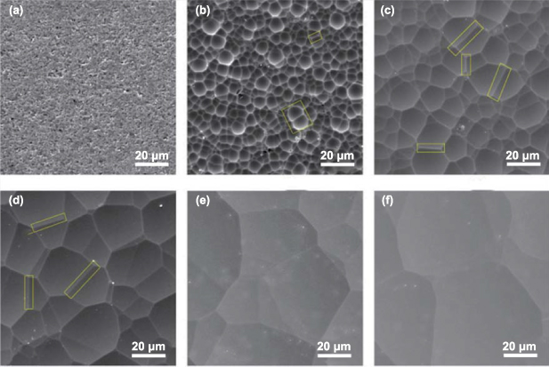
Figure 40. The topography of the etched surface characterized by SEM. Reprinted from [287], Copyright © 2015 Elsevier B.V. All rights reserved. (a) Original surface; (b) 20.6 μm; (c) 45.3 μm; (d) 95.2 μm; (e) 164.6 μm; (f) 300 μm.
Download figure:
Standard image High-resolution imageTo sum up, the non-contact machining of LMP, MRF, IBF, and APP greatly helps to improve the surface quality of DMMs components after FAC. Their main features, advantages, and disadvantages are listed in table 7. LMP uses the laser to heat the workpiece surface and reshape the surface morphology by melting or spalling, so as to obtain a smooth surface without cracks or defects. This method has the advantages of high efficiency, high precision, easy integration, and no pollution. But it has little effect on improving the shape accuracy, and it is easy to generate oxide deposition on the workpiece surface. MRF is a FAM method that inputs high density magnetic field energy into the processing area and cooperates with traditional machining methods to achieve efficient removal of difficult to process materials. The removal function of MRF is stable, but for large gradient surfaces, the error smoothing ability is poor, with low efficiency and high cost. IBF achieves non-destructive removal of materials through physical atom sputtering in a vacuum environment. This method has the advantages of good stability and less impurity without polishing edge effects and subsurface damage, but it is inefficient and expensive. APP is to change the material properties or generate volatile substances through the reaction of active particles and the workpiece surface, so as to realize the processing of the material. A great removal effect on the damage of the machined surface and subsurface is achieved by APP. However, the processing materials are limited by the reaction between the active particles and the surface material of the workpiece, the crystal structure of the matrix surface will change, and the long-term removal stability and thermal effect will be poor.
Table 7. General characteristics of field-assisted surface quality improvement methods.
| Methods | Main features | Advantages | Disadvantages |
|---|---|---|---|
| LMP | Use laser irradiation to reshape the surface topography by melting or peeling. | Suitable to most light-absorbing materials; high efficiency, easy integration and pollution-free. | Limited improvement in surface accuracy; possible redeposition of material. |
| MRF | Magnetic field changes the flexibility of magnetic fluid to achieve material shear removal. | The removal function is stable without subsurface damage. | For large gradient surfaces, the error smoothing ability is poor. |
| Low efficiency and high cost. | |||
| IBF | In vacuum environment, atomic scale removal is realized by physical atom sputtering. | Achieve sub-nanometer surface accuracy without edge effects, frictional stress, and subsurface damage. | The processing is inefficiency and expensive. |
| APP | The materials are removed by chemical reaction between plasma and material surface. | No mechanical stress and sub-surface damage, high processing efficiency. | Poor long-term removal stability and thermal effects. |
5. Discussions and summary
In recent years, with the increasing performance of advanced optoelectronic systems such as free electron laser light source, ultraviolet lithography, and space detection, the machining accuracy of core components has been gradually improved to the nano level or even atomic level. Meanwhile, there is an expanding range of materials that need to be machined. Traditional ultra-precision machining faces challenges in meeting the requirements of advanced optoelectronic systems because of the large cutting force and high cutting temperature, resulting in tool wear and low surface quality, as summarized in figure 41(a). To overcome these limitations and deeply analyze the interaction mechanism between tools and workpieces, as outlined in figure 41(b), three main aspects can be carried out: (1) material modification, manifested as reducing the hardness and fracture toughness of the material, improving the thermal conductivity, and enhancing the machinability of the material. (2) Energizing tool, that is to change the motion state of the tool and improve the strength of the tool. (3) Tool-workpiece contact status amelioration, manifested by increased lubrication, reduced tool-workpiece contact time, and lower cutting temperatures.

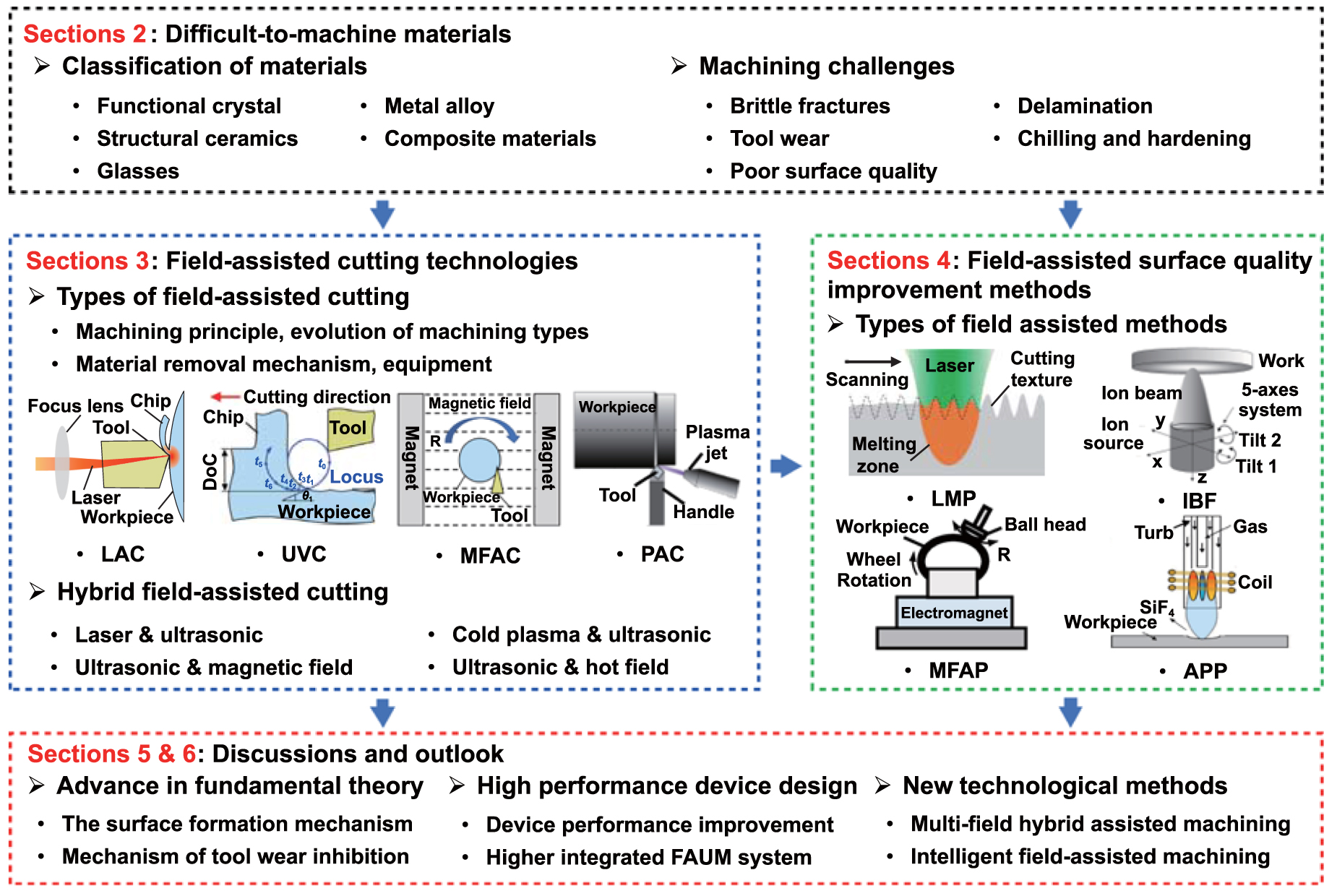
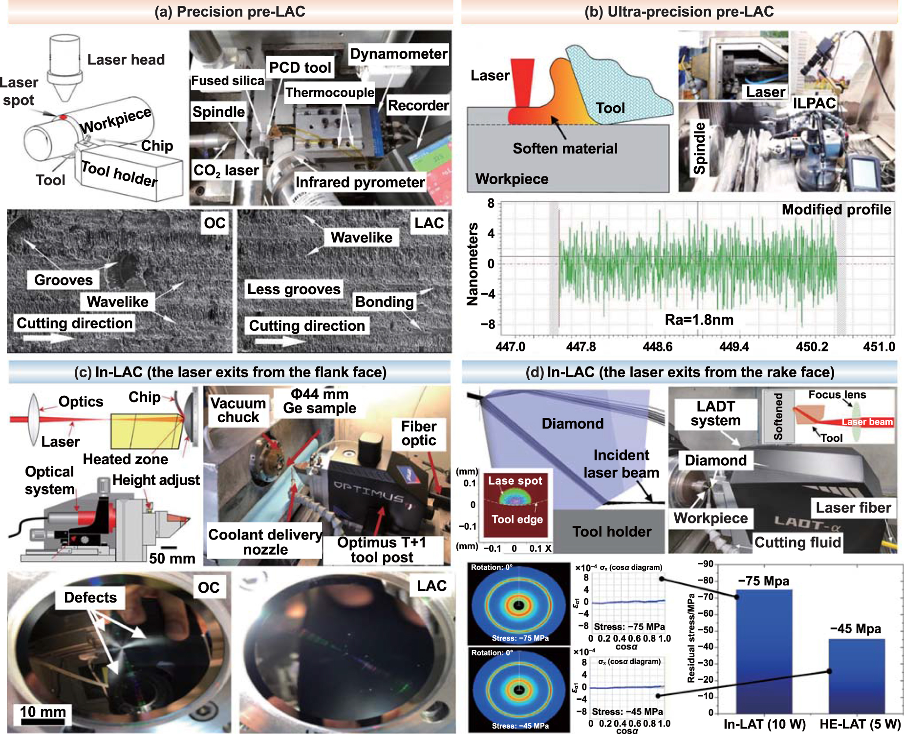
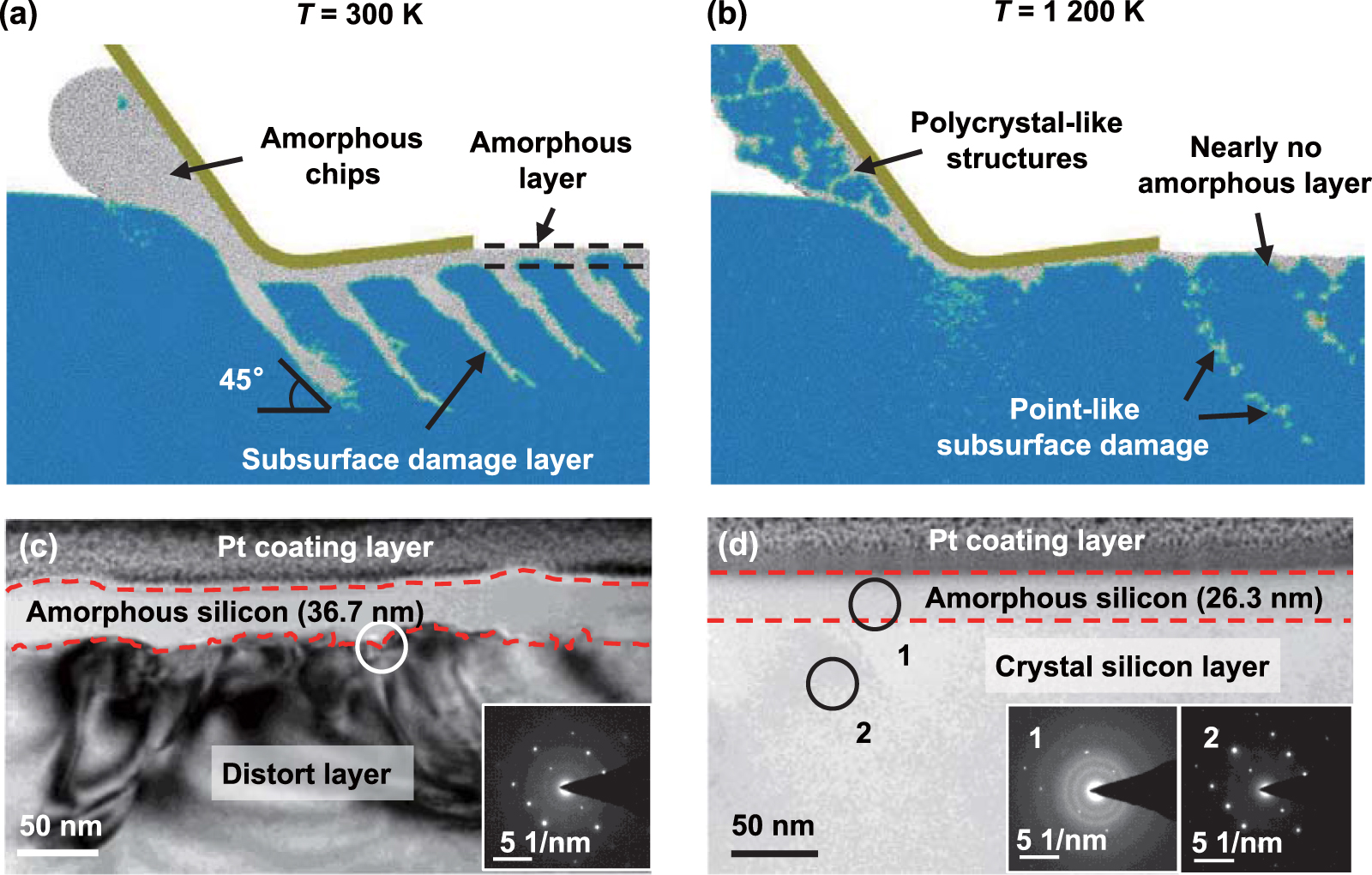
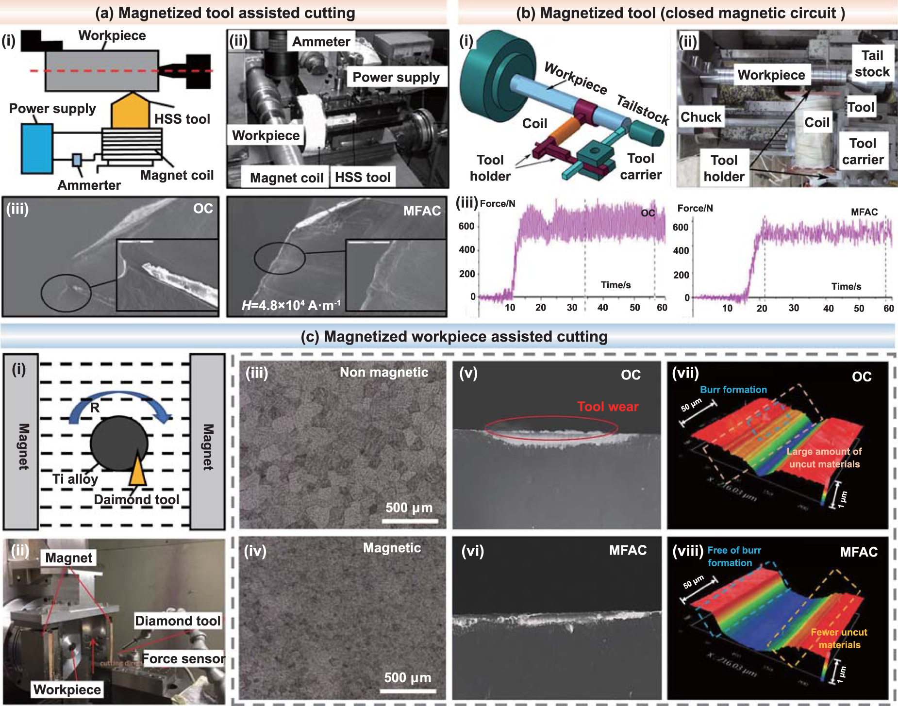
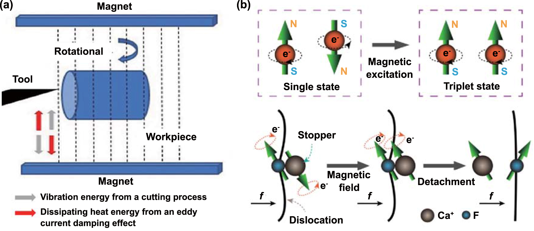
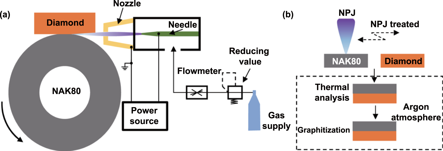
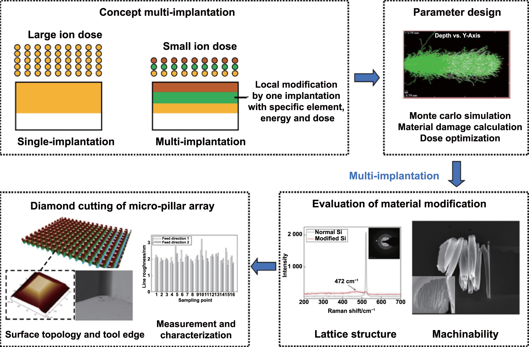
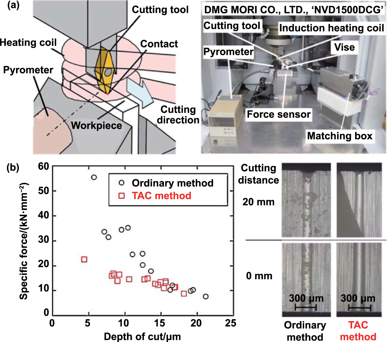
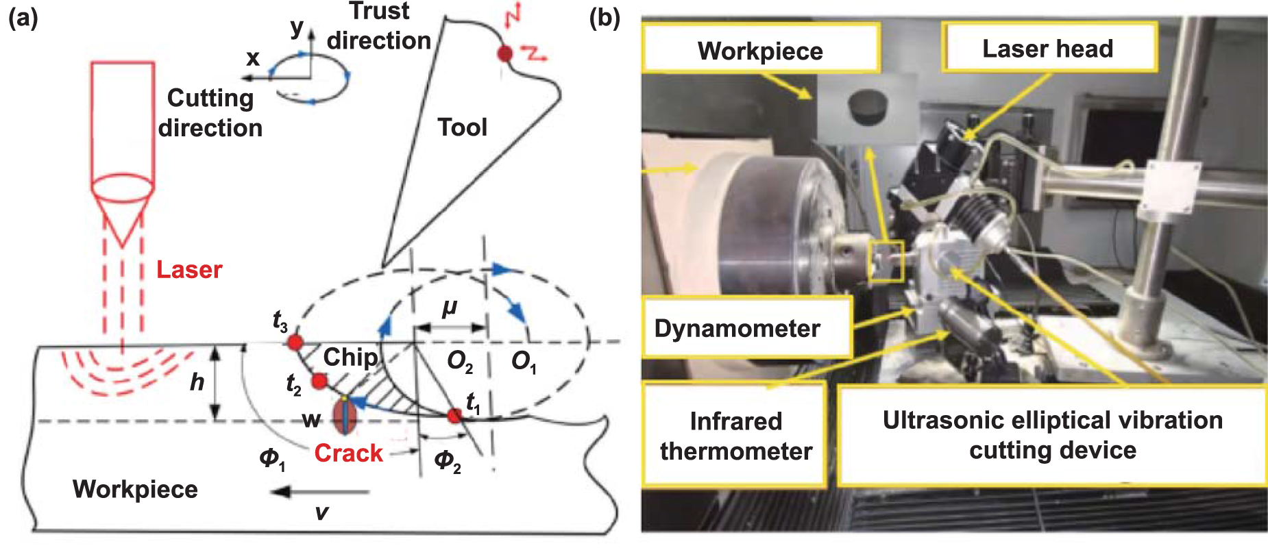
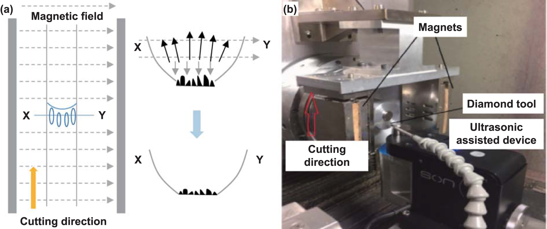
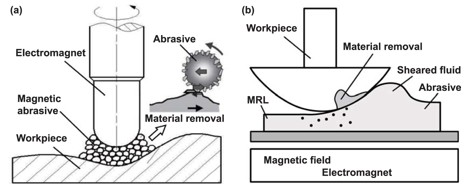
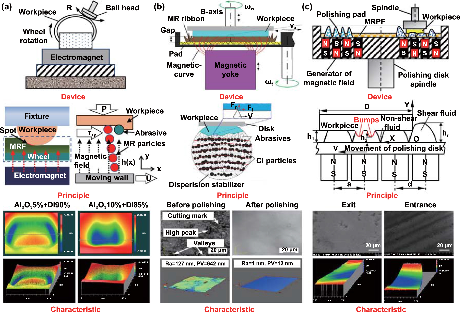
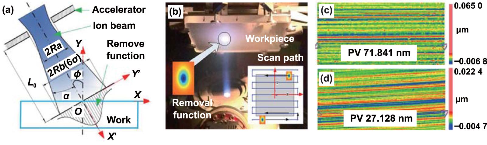
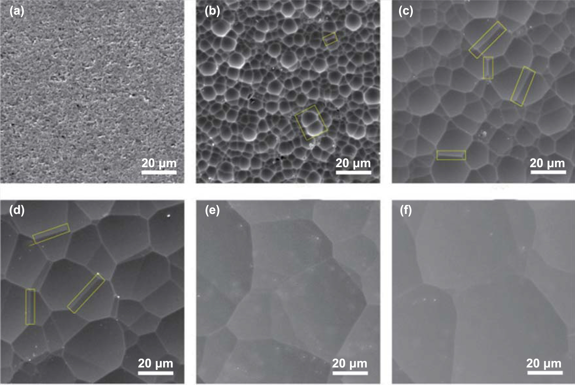
Figure 41. Summary of typical field-assisted machining strategies for DMMs. (a) Challenges of DMMs ultra-precision machining. (b) Research ideas to improve machining quality. (c) Typical field-assisted strategies. (d) Benefits and limitations of typical field-assisted strategies.
Download figure:
Standard image High-resolution image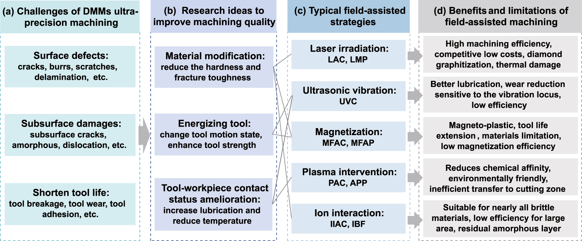
Based on the above ideas, researchers have proposed FAM based on laser, ultrasonic, magnetic field, plasma, ion implantation, etc, which significantly improve the machining quality of components, as summarized in figure 41(c). This paper discusses the research progress of FAM in recent years and systematically introduces the basic principles, equipment design, and typical applications of different assisted machining methods. It is observed that each FAM strategy has its own benefits and limitations in improving the machining quality of DMMs, as shown in figure 41(d).
Laser radiation, such as LAC and LMP, modifies materials by laser heating. Specifically, the low-power laser (LAC) softens the material to enhance the elastic-plastic deformation of the material, while the high-power laser (LMP) reshapes the surface topography by melting or peeling. For LAC, it is mainly suitable for materials with high hardness, room temperature impact brittle fracture, and high heat absorption ratio, such as crystals, ceramics, cemented carbide, etc. On the other hand, LMP can be applied to various difficult-to-process materials except those prone to gasification or oxidation under laser irradiation. Laser irradiation enables real-time surface modification with advantages of high processing efficiency and low cost, but it also carries potential risks of thermal damage like residual thermal stress and surface oxidation. UVC alters the motion state of a tool by applying high-frequency vibration, which reduces the cutting temperature and main cutting force at the position of the tool nose and increases the lubrication of the cutting area, to achieve nano-scale material removal and suppress tool wear. UVC is especially suitable for metal alloys, crystals, composite materials, etc, but not recommended for high hardness materials. In addition, UVC is sensitive to the vibration locus, requiring strict control of the cutting speed, and the processing efficiency is relatively low.
The magnetic field mainly improves the processing quality through two aspects. One is that the magnetic effect refines the grain structure of the material and induces the magneto-plastic effect to improve the machinability of the material. The other is to control the movement of the tool or enhance the strength of the tool to achieve efficient processing. MFAC is mainly employed for magnetic materials like titanium alloy and steel alloy as well as materials prone to magnetizing plasticity such as CaF2 and ZnS. The range of materials processed by MFAC is limited, and there are cases where the magnetization efficiency is too low. There is no material limitation in MFAP, and the improvement of machining efficiency is the main problem in its application. Plasma intervention such as PAC and APP, is a clean auxiliary strategy that can effectively control complex thermal conditions. PAC is suitable for materials with strong affinity for tool carbon atoms such as steel alloys and titanium alloys. But it is difficult to be effectively delivered to the machining area during micro-nano-scale machining. In ion interaction (such as IIAC and IBF), material defects caused by ion impact on the workpiece absorb the core of machining energy to prevent brittle fracture. IIAC is suitable for almost all non-metallic crystals such as Si, Ge, and SiC. IBF has no material restrictions, but for large-sized workpieces, the processing efficiency is low. Moreover, the substrate surface damage caused by ion modification, such as crystal distortion and amorphization, is difficult to completely remove.
6. Future research perspectives
The massive application of FAM still faces challenges. Continuous advances in FAM technology have been made possible by improving the understanding of DMMs ultra-precision machining requirements. The future studies of FAM technology can be summarized as follows:
6.1. Advance in fundamental theory of FAM
In the FAM process, due to the introduction of tool vibration, laser heating, magnetic field modification, and other effects, the material deformation and removal in FAM is a multi-field coupled process that integrates elastoplastic mechanics, microscopic heat transfer, tribology, and other disciplines. Currently, the investigation of FAM primarily concentrates on machining surface quality and application effectiveness, while basic theories such as surface formation mechanisms and tool wear mechanisms remain insufficient.
LAC softens DMMs for plastic removal but high softening temperatures can aggravate tool wear. Hence, it is essential to deeply analyze the tool wear mechanism under thermal field. UVC is an intermittent machining method. It effectively decreases cutting force, reduces tool wear, and enhances surface machining accuracy. The high frequency impact produced by vibrating tool cutting workpiece is easy to cause micro cracks on the workpiece surface. It is necessary to study the correlation mechanism of tool impact on surface machining quality and subsurface damage. MFAC is a processing method to achieve efficient removal of DMMs. At present, research on cutting mechanism under thermal-magnetic-force coupling is relatively scarce.
PAC significantly reduces tool wear and improves the machinability of DMMs, the coupling mechanism of cold plasma jet hydrophilic modification and lubricating medium needs to be further studied. IIAC employs ion implantation to reduce the hardness and brittleness of the workpiece. However, ion stimulation can cause crystal damage and amorphization on the workpiece surface. How to reduce the above-mentioned damage effects during ion implantation requires further research. By coupling the gain effect of different fields, HFAC could significantly improve the machinability of DMMs. However, the material removal mechanism under the hybrid fields needs further elucidation.
In field-assisted surface quality improvement methods, LMP is easily oxidizes the workpiece, affecting the surface material properties. It is necessary to investigate the oxidation mechanism and the optimization of laser parameters to inhibit oxidation. The research of the material removal model of MFAP is limited to theoretical modeling and fitting surface, which is difficult to be applied to practical processing. In the future, the real-time measurement technology can be used to measure the polishing process online, optimize the model and realize the accurate control of the polishing process. The processing efficiency of IBF is low, so it is necessary to develop a faster, more efficient, and more accurate algorithm for dividing the polishing trajectory and solving the feed speed. APP is greatly affected by temperature and long-term removal stability is poor, thus affecting the surface quality improvement. It is necessary to study the plasma discharge theory and temperature conduction mechanism to achieve accurate calculation of the removal function.
6.2. The performance enhancement and integrated design of FAM devices
Recently, a variety of FAM devices have been designed based on the field-assisted mechanism, and their usefulness has been demonstrated in various DMMs. To further improve the machining quality in the future, FAM devices can be developed in both performance enhancement and integrated design directions. In LAC, it is necessary to optimize the laser optical path and establish the mapping relationship between the tool path of complex surface tool and laser position to improve the laser control accuracy. Continuous laser heating will affect the tool life, so it is necessary to design an effective tool cooling strategy. The UVC system with high power and large amplitude needs to be further upgraded to improve the machining efficiency of industrial applications. Based on the piezoelectric crystal drive detection integration method, combined with the machining trajectory of the tool, a machining-detection-compensation integrated UVC system can be designed to promote processing accuracy. In MFAC, the effective magnetic field that can be used in the machining area only accounts for a small part of the total magnetic field. It is essential to establish a controllable method of high-density magnetic energy accumulation technology to enhance the magnetization effect. In addition to the laser field as the heat source of TAC, it is difficult to realize the precise application of the heat source in the actual processing process, which makes it difficult to accurately control the temperature and easily aggravate the wear of the tool. More efficient ways to control the application of heat sources need to be found. The equipment compatibility of hybrid fields is the issue restricting the development of the HFAC system. It is imperative to study the coupling design approach of hybrid fields and develop an HFAC system which is easy to operate and integrate.
In field-assisted surface quality improvement methods, the LMP system has high removal efficiency, but it is susceptible to generating oxidation deposits on the machined surface. Innovative methods such as water isolation and magnetic field induction can be explored. The removal function of MFAP and IBF systems is stable, but the machining efficiency is poor and the cost is high. The future system design needs to decrease the system complexity, reduce the equipment cost, and optimize the resident duration solving algorithm to promote engineering applications. There will be residual sediment on the workpiece surface processed by APP. It is necessary to improve the processing conditions, such as using a larger flow of Ar to form an atmosphere to protect the workpiece surface. In addition, the integration of FAC and surface quality improvement methods, which shorten the process flow and increase efficiency, is also the trend of future FAM devices.
6.3. Multi-field hybrid and intelligent field-assisted machining
According to the machining requirements of DMMs, multi-field hybrid assisted machining technology combines single-FAM method, which can effectively assimilate the advantages of high-performance surface forming induced by a single physical energy field, and realize high-quality machining of DMMs components. For example, combining LAC, UVC, and MFAC technologies can greatly increase the critical depth of cut, reduce surface damage, suppress tool wear, and reduce the destructive effects of high-frequency impact and active vibration of the tool. At present, multi-field hybrid assisted machining is facing new challenges such as multi-field convergence and control strategy, material removal mechanism under multi-field coupling, and integrated equipment development. With the continuous development of artificial intelligence technology, it has brought a new development direction for FAM. For example, for multi-phase DMMs (such as SiCp/Al), FAM provides new ideas for improving material machinability, but owing to the different nature of different phase materials, brittle boundary fracture defects, and other phenomena can be caused, affecting the improvement of surface quality. Selective intelligent FAM technology converging machine vision is a promising approach to achieving ultra-precision machining of multi-phase DMMs in the future. This method uses machine vision to accurately identify different phases, and controls the energy field for selective machining, thereby obtaining a high-quality processed surface. The synergistic removal mechanism of multiphase materials under the selective application of the energy field, the high-quality identification of material components, and the intelligent regulation of the energy field are the research directions that need to be broken through urgently.
Acknowledgments
This work was supported by the National Key Research and Development Project of China (Grant No. 2023YFB3407200), the National Natural Science Foundation of China (Grant Nos. 52225506, 52375430, and 52188102), and the Program for HUST Academic Frontier Youth Team (Grant No. 2019QYTD12). We would also like to thank Dr Jinyang Ke, Dr Gui Long, Dr Shanyi Ma, Dr Mao Wang, Dr Yujiang Lu, Dr Hao Sun, Dr Zongpu Wu, and Dr Yang Hu for compiling the cited literature in this paper.