Abstract
The search for gravitational wave signals from astrophysical sources has led to the current work to upgrade the two largest of the long-baseline laser interferometers, the LIGO detectors. The first fused silica mirror suspensions for the Advanced LIGO gravitational wave detectors have been installed at the LIGO Hanford and Livingston sites. These quadruple pendulums use synthetic fused silica fibers produced using a CO2 laser pulling machine to reduce thermal noise in the final suspension stage. The suspension thermal noise in Advanced LIGO is predicted to be limited by internal damping in the surface layer of the fibers, damping in the weld regions, and the strength of the fibers. We present here a new method for increasing the fracture strength of fused silica fibers by laser polishing of the stock material from which they are produced. We also show measurements of mechanical loss in laser polished fibers, showing a reduction of 30% in internal damping in the surface layer.
Export citation and abstract BibTeX RIS

Content from this work may be used under the terms of the Creative Commons Attribution 3.0 licence. Any further distribution of this work must maintain attribution to the author(s) and the title of the work, journal citation and DOI.
1. Introduction
The sensitivity of the coming generation of gravitational wave detectors currently being installed will in part be limited at frequencies between 10 and 100 Hz by Brownian motion of the mirrors and their suspensions [1]. Future upgrades to these detectors will require a reduction in suspension thermal noise, and extension of the bandwidth to lower frequencies to increase sensitivity in a region thought to contain many astrophysical sources.
Research into reducing suspension thermal noise in future detectors is primarily focused on use of cryogenics, and a switch to a more appropriate material for low temperature such as silicon [2, 3]. However it is possible that there will be further efforts before this to make incremental upgrades to the room temperature detectors, for example by increasing suspension length or mirror mass [4]. We discuss here the effects which limit the performance of fused silica fibers as a suspension material and will show improvements that can be achieved using a new technique of laser polishing the stock material from which the fiber is pulled.
Brownian noise, described by the fluctuation–dissipation theorem [5–9], can be reduced in the detection band by use of low mechanical dissipation materials, of which fused silica is currently favored for use at room temperature [10–16]. The power spectral density of this thermal noise for a pendulum, well above the frequency of its fundamental mode, may be written as

where ω is the angular frequency, m is the mass of the suspended mirror, T is the temperature, ω0 is the angular frequency of the pendulum mode, kB is the Boltzmann constant and ϕ(ω) is the pendulum loss angle. Dissipation in fused silica occurs due to internal friction and thermoelastic damping. The frictional losses can be described by two components, damping in the bulk of the material and damping in a thin lossy surface layer. The dominant source of loss depends on the surface to volume ratio of the piece. In larger pieces, such as test masses, the dissipation is dominated by a frequency dependent damping in the bulk of order ϕb ≈ 10−9 [15, 17]. In thin fibers with radius r < 0.5 mm the dissipation, which can be shown to be inversely proportional to radius [18, 19], is consistent with damping in a thin lossy surface layer

where h is the thickness of the lossy surface layer and ϕsurface is the loss angle of this layer. The exact nature of this lossy layer is not known, but it may be caused by surface cracking or contamination. Dissipation in this layer is of the order ϕsurface ≈ 10−5, assuming a lossy layer thickness of around 1μm [18, 20]. For any size piece of silica there will be contributions from both surface loss and bulk loss according to the ratio of total energy stored in each [15].
Temperature fluctuations in the fiber cause volumetric change, creating an additional source of displacement noise known as thermoelastic noise. For a fiber under tension there are two components to this, one arising from the thermal expansion coefficient [21–23] and the other from the temperature dependence of the Young's modulus [23]. The full thermoelastic loss is given by:

where Y is the Young's modulus, ρ is the density, α is the thermal expansion coefficient, C is the volumetric specific heat capacity, m is the suspended mirror mass and β is the fractional change in Young's modulus with temperature. τ is the characteristic time for heat flow across the fiber, which for a circular cross section is given by

where κ is the thermal conductivity and d is the fiber diameter. From equation (3) it can be seen that for a 40 kg aLIGO test mass suspended on four fused silica fibers, it is possible to cancel thermoelastic noise for a fiber of r ≈ 410 μm, for typical values of the material properties. Indeed the Advanced LIGO suspensions will use this effect to cancel thermoelastic losses [23–25].
The mechanical loss factor for the pendulum mode of a mass suspended on a wire may be significantly smaller than the loss factor of the wire itself, an effect known as 'dilution'. If one considers a swinging pendulum, the mass at the end of the pendulum rises and falls providing a gravitational restoring force that is without dissipation. The wire suspending the mass is deformed as the pendulum swings, and this deformation does cause dissipation of energy dependent on the material loss factor of the wire. The dilution factor is the ratio of potential energy stored in lifting the mass, to energy required to deform the wire [26] and the total pendulum loss is the material loss of the wire divided by the dilution

where L is the fiber length. In practice there are extra effects due to non-ideal fiber shape and transitions from thin fiber to test mass [27, 28]. To attach the fiber to the mass an interface piece or 'ear' is bonded on each side of each mass. The ears have shaped 'horns' to which the fibers are welded. This non-ideal transition from thin fiber to test mass results in a reduction in the dilution effect and an increase in suspension thermal noise. The full loss is given by

where ϕt is the thermoelastic loss, ϕb is loss due to damping in the bulk material, and ϕs is loss due to dissipation in the lossy surface layer.
The 4 km separation of the LIGO test masses causes a coupling between vertical and horizontal motion at the level of 6 × 10⁻⁴ due to the difference in direction of the gravitational force on the two mirror suspensions [1]. Other mechanical couplings will exist, and for our designs we conservatively round the total up 1 × 10⁻³ for our designs [1]. At the frequency of the lowest vertical bounce mode this produces a pronounced peak in the displacement noise. In order for the gravitational wave detection band to be opened up to lower frequencies, this noise source, along with others including gravity gradient and seismic noise, will need to be reduced. Under the current design, the vertical bounce mode frequency is set by the cross-sectional area and length of the fused silica fibers in the final stage of the suspension. For a mass suspended from a cylindrical fiber this is given by  . However for a multistage suspension such as those in Advanced LIGO, the test mass is suspended from a penultimate mass which itself is suspended. The final frequency for Advanced LIGO is approximately
  times this frequency, since the penultimate mass has the same mass as the test mass, and the mode of oscillation sees the two masses moving in opposing directions.
The fibers that are being installed in the Advanced LIGO gravitational wave detector suspensions have a dumbbell shape [29, 30], where the diameter of the ends of the fibers is set to cancel the thermoelastic losses. The central section of fiber is thinned down to r = 200 μm to reduce the vertical bounce frequency to 9 Hz [1]. As a result, the largest source of loss in the fiber is surface dissipation, although in practice there will be residual thermoelastic loss arising from bending energy in the fiber neck and ear and there may also be loss in the weld area [16, 28]. The diameter of fiber at the ends is thus fixed and cannot be increased or decreased without increasing thermoelastic losses. To further reduce the horizontal component of Brownian noise at room temperature in a fused silica suspension there are two remaining possibilities: increase the length of the suspension or decrease the dissipation of the surface layer.
The vertical noise contribution is ultimately limited by fiber strength, and the length of the suspensions. There are several possible ways to achieve a lower bounce frequency, including lengthening the suspension or inclusion of low loss cantilever blades in the final stage of the suspension. However such additions would not be easy, and would require significant reworking of the design and possibly infrastructure.
It has previously been shown that flame polishing fused silica fibers can increase the fracture strength [31], and CO2 lasers have also been used to achieve reduction in surface roughness of fused silica [32]. We present here a method for increasing the strength of fused silica fibers by pre-polishing the stock material from which the fiber is drawn using a CO2 laser. Increasing the fracture strength of fibers would allow the use of thinner fibers, which would in turn reduce the suspension bounce frequency without requiring any infrastructure change. Measurements of the mechanical dissipation in these fibers are given in this paper, and demonstrate a small but measurable reduction in the internal damping of the surface layer as a result of laser polishing.
2. CO2 laser polishing of fused silica
2.1. Surface cracking and flame polishing
The role of surface cracks in the strength of brittle materials was first described mathematically by Griffith [33]. He showed that for a perfectly elastic brittle material which exhibits no plasticity, the breaking stress was inversely proportional to the square root of the depth of the crack

where σ is the breaking stress, c is the depth of the crack, K is the material fracture toughness and B is a geometrical constant (∼1) dependent upon the shape of the crack. The fracture toughness of fused silica is in the region of 0.8  [34].
[34].
For practical purposes the strength of a fiber may be increased if we can either reduce the depth of the crack, or reduce the sharpness of the tip of the crack as parameterized by the geometrical constant B. This is typically achieved in glassy materials by flame polishing or etching. Flame polishing involves heating the surface to a temperature where it can flow, allowing the cracks to 'heal' under the influence of surface tension and sharp geometric features to be rounded off [31, 35]. As molten silica cools, gradients in temperature leave residual thermal stresses in the glass. To achieve the highest strength, glasses may be annealed to remove the residual thermal stresses.
It is interesting to note that in a recent strength study of fused silica fibers it was seen that there was no significant correlation between fiber length and breaking stress as would be expected from the Griffith crack propagation theory [35]. An alternative cause for fracture, stress corrosion, was postulated in which cracks form under stress in a pristine surface. In our work we cannot distinguish between these two effects. However it is clear that pre-polishing the fused silica stock material produces an effect that either reduces cracks in the pulled fiber surface, or changes the surface properties of the fiber such that it reduces the crack formation rate.
2.2. Laser polishing
Flame polishing is often used to reduce cracking in the surface of fused silica, usually for the purpose of improving strength. The flame used for flame polishing has a gas velocity that can cause distortions in the molten surface. There is also a danger that particles emitted either by the torch, or entrained in the air, can be blown onto the surface of the glass. Finally, a byproduct of hydrogen-oxygen torches, used to heat fused silica, is water. Water is known to increase sub-critical crack growth in fused silica through a process thought to involve a reduction of bond strength in stressed bonds at the crack tip [34]. However it is not clear whether the super heated water from a gas torch causes such damage since the surface of the silica is also heated to high temperature. A high power CO2 laser can also be used to heat the fused silica and thus polish the surface, bringing several advantages. The laser by comparison heats by radiation, having no gas velocity or byproducts.
Instead of polishing the fiber after pulling, a method was used whereby the stock material was polished before the fiber was pulled. The Advanced LIGO gravitational wave detectors use fibers that taper to a 400 μm diameter through the central section [1]. The fibers are so thin that the thermal stress generated by attempting to polish the fiber directly leads to a significant decrease in the ultimate strength. Attempting to anneal fibers in an oven after directly polishing the fiber surface was not found to recover the strength, and we postulate that this may be due to contamination or cracking of the surface during this extra annealing process [36].
We have found that touching the fiber surface after it is pulled easily generates surface cracks which can severely decrease the fiber strength. For this reason the fibers were not touched after production, and the fibers were only handled by the thicker stock sections at the ends. The stock material from which the fibers were pulled may not have been handled as carefully as this, and indeed the handling of the material prior to arriving from the manufacturer is unknown to us. The silica stock is stored with the surface touching the plastic packing material. After removing from this packing it is handled using gloved hands while preparing the stock for pulling. The surface must be cleaned before using the stock material to remove contaminants that would decrease fiber strength and increase mechanical loss. The cleaning process involves use of acetone and methanol applied with synthetic wipes. Surface cracking may be greatly increased by any or all of these processes.
It was found early on in testing that fibers pulled using a low laser power resulted in a weaker fiber. Existing defects in the silica stock were not removed during the pulling process. Fused silica does not have a sharp solid-liquid transition temperature, but instead the viscosity decreases exponentially with the temperature increase [37]. It is possible to heat silica to the point where the viscosity is low enough to pull into a fiber, but still high enough that during the 30 s pulling period there is not time for cracks to heal over in the highly viscous material. Heating to a higher temperature during pulling improves this by reducing the viscosity. A practical upper limit to the temperature of the surface during pulling is reached when it begins to vaporize. Instead of further increasing the temperature used during the pull, we postulated that by carefully polishing the stock material before pulling the fiber, surface defects in the resulting fiber might be reduced.
After pulling the fiber from the stock material, the end pieces of stock material are still attached and are used to clamp the fiber during strength testing. A second failure mechanism during destructive testing is for the fiber to break in one of these end pieces. This is particularly likely for fibers that have not undergone polishing since the surface of the stock is untreated, while the thin section of the fiber has been heated. The polished fibers by contrast, also had the end stock polished resulting in far fewer breaks in the ends. It should be noted that it was not always clear which section of the fiber broke since the energy in breaking is significant and often resulted in the fiber being broken along much of its length.
The machine shown in figure 1 was used to pull the fibers from a 3 mm diameter fused silica rod, using a process described in [38]. The same apparatus was also used to polish the stock material before pulling. The laser was reflected from a rotating mirror, shown in figure 2, onto a lower conical mirror. This lower conical mirror directs the laser light upward onto an upper conical mirror which reflects the beam inward, onto the fused silica stock which sits at the center of this upper mirror. This allows the silica to be heated uniformly from all sides. It can be seen in figure 2 that as the beam passes up from the lower conical mirror to the upper one, there are three spokes holding the lower clamp. These will cause three small shadow areas on the silica that are not directly exposed to laser radiation. However the polishing effect is caused by heat rather than direct exposure to laser radiation, and hence these small sections are polished by conduction of heat from the surrounding areas. To polish the length of the silica stock, the laser was turned on and the circular beam pattern was slowly moved down over the silica stock. Starting from the top the beam was moved toward the bottom before reversing the direction and moving back to the top again, with the final part of the polish always done from bottom to top to remove silica vapor from the surface. A laser power of approximately 80 W was chosen, that heated the silica to a temperature just below the point of vaporizing the surface. The vapor point fused silica is approximately 2700 C [39]. The length of time for the polishing was varied to look for a correlation with strength, with the slowest polish taking 3000 s to move the laser up and down over a 45 mm section of rod, a speed of 3 × 10⁻⁵ m s−1. A useful measure of polish is the incident energy per unit area. For an incident laser power of 80 W and beam diameter of 3 mm the energy per unit area can calculated to be approximately 6 × 10⁸ J m−2. The fibers were then pulled and carefully removed from the machine without touching their surface.
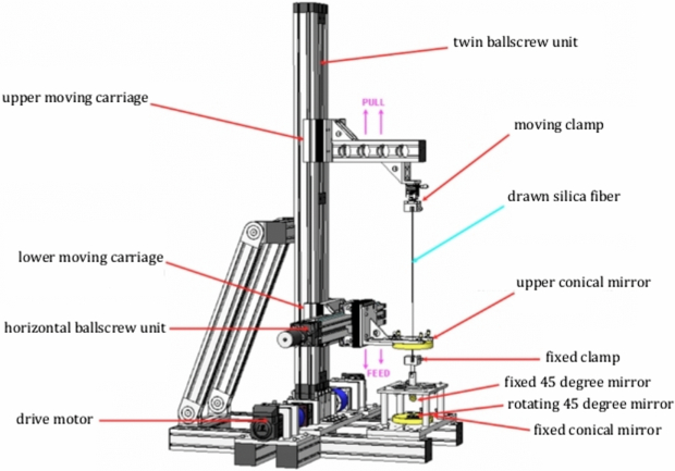
Figure 1. Diagram of the CO2 laser pulling machine.
Download figure:
Standard image High-resolution image
Figure 2. Diagram of the optical layout of the laser pulling machine. The CO2 beam is reflected from a rotating mirror onto a lower conical mirror. This reflects a cylinder of laser light upward onto an upper conical mirror which directs the beam onto the fused silica stock, heating it from all sides.
Download figure:
Standard image High-resolution imageThis apparatus is used to both polish the stock and pull the fibers for the Advanced LIGO suspensions, currently being installed. A similar machine was built by the University of Glasgow at the Virgo site in Italy where it has been used to produce fibers for the Advanced Virgo detector. Both Advanced LIGO and Advanced Virgo will use some form of laser polishing of their fibers [24, 40], with Advanced LIGO fibers being polished using the method described here.
3. Strength testing
fibers were pulled with a range of polishing times up to a maximum of 3000 s. The diameter along the length of each fiber was measured using the profiling machine described in [41]. The fiber dimensions were chosen to be close to those planned for use in Advanced LIGO, including 820 μm diameter dumbbell shaped ends, a 400 μm diameter central section, and a length of 60 cm. The fibers were then destructively tested using the apparatus shown in figure 3. The fiber is clamped at both ends using self-tightening wedge type of clamp. Before clamping the stock at the ends of the fiber, small cardboard pieces were epoxy bonded to the surface of the end pieces to increase the friction against the clamp surface. The top clamp is attached to a load cell, used to measure the maximum force applied before breaking. The lower clamp is attached to a linear drive system driven by a motor with a reduction gearbox that allowed the applied force to be increased slowly.
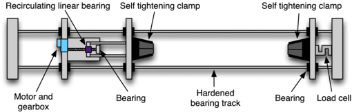
Figure 3. Destructive strength tester, used to find failure loading for fused silica fibers. The fiber is clamped in a self-tightening wedge type of clamp before being loaded along its axis using a recirculating linear bearing drive to ensure a smooth increase in load. The failure load is recorded using an s-beam type strain gauge load cell.
Download figure:
Standard image High-resolution imageThe results of this testing are shown in figure 4. Two variations on the polishing method were tested. In the first variation, the silica was polished by moving the laser down and back up over the stock material and the total time was recorded. In the second variation, the samples were prepared as in the first, but with the process repeated after cooling. The total time for the two polishings was recorded. This set of data was taken to look at whether any advantage could be gained from repeated polishing of the stock. fibers were also pulled with no initial polish, shown in figure 4 as circular points at zero seconds polishing time. Finally a set of fibers were pulled by turning the laser power down as low as possible while still being able to draw the silica, and these fibers are shown as blue crosses at zero seconds polishing time.

Figure 4. Destructive loading of 400 μm diameter laser polished fused silica fibers as a function of polishing time. Light blue diamond points are fibers that were polished once (moving the laser down over the rod and then back up to the starting point again). Orange square points are fibers that were polished twice, with the total polish time shown here. The green circular points are fibers pulled with no polish. The blue crosses show a set of fibers pulled using a low laser power and no polishing.
Download figure:
Standard image High-resolution imageFigure 4 shows a clear correlation between polishing time and strength. For comparison, the fibers that are to be used in Advanced LIGO will be under a static load of 10 kg, and a factor of three in strength, 30 kg, is required to ensure safety of the suspensions. We see from figure 4 that in order for the laser pulled fibers to achieve this strength, some form of polishing or pre-selection of fibers is required. Even a short polishing time is seen to improve the minimum strength to above the required level. This may in part be due to reducing the number of breaks in the stock material, which was typically not seen to break in the fibers that had been polished. It is apparent that there is no significant advantage to repeatedly polishing the stock, and that instead it is the total time the silica is heated that is important. The error in this measurement is taken to be the error in measured breaking load which is 0.05 N.
A number of laser pulled fibers of varying diameter were produced and strength tested, with these data being shown in figure 5. The stock material was not polished before pulling these fibers. Figure 5 shows a clear inverse relationship between breaking stress and fiber diameter. Such an inverse relationship between breaking stress and diameter can be found in the literature [42], though other studies [35] have not seen such a relationship, suggesting that this is dependent on the method of fiber preparation and measurement. The error in these data is taken to be the variation in the average of the measured diameters, approximately 0.5%.
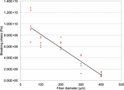
Figure 5. Diameter dependence of breaking stress of laser pulled fibers, pulled from unpolished fused silica stock.
Download figure:
Standard image High-resolution imageConsidering the improved strength from laser polishing and an inverse diameter dependence to breaking stress, it was hypothesized that the safe static overload of 30 kg could be achieved with a significantly smaller diameter of fiber. By taking the breaking load achieved for the fibers polished for 3000 s, and scaling it inversely with diameter, a thinner diameter fiber design was found that should still achieve an average breaking strength higher than that required. Five fibers were produced, with their diameters measured to be 288 μm, each having been polished for 3000 s. The results gave an average breaking strength of 32.4 kg, maximum strength of 35.1 kg and a minimum strength of 30.2 kg, just above the requirement of 30 kg.
Using a 288 μm diameter fiber in a future upgrade to the Advanced LIGO suspensions would allow the vertical bounce mode of the final stage of the suspensions to be moved from 9 Hz to just below 6.5 Hz. Perhaps most importantly, this relatively straight forward upgrade would require no infrastructure change while retaining the factor of 3 safety margin over the static loading.
4. Mechanical loss measurements
Dissipation in the fibers was measured using a mechanical ring down technique. Three fibers were chosen for analysis. The first fiber was pulled from unpolished stock. The second and third fibers were pulled from stock that had been polished for 550 s and 3000 s respectively. The fiber under test was welded into place at the bottom of a fused silica double pendulum, as shown in figure 6, and the system pumped down to below 10−7 Torr.
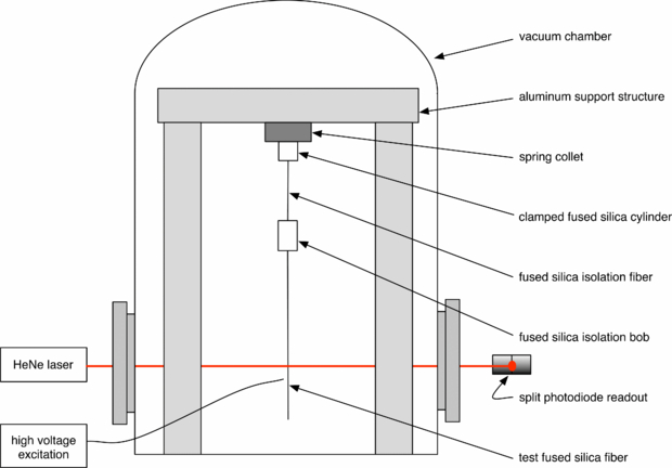
Figure 6. Ringdown measurement apparatus to measure the mechanical loss of fused silica fiber resonant modes.
Download figure:
Standard image High-resolution imageThe loss angle of individual cantilever bending modes of each fiber was measured by exciting a mode using an electrostatic driver which was then disconnected, and the ring down recorded using a shadow sensor.
For each fiber the loss of each cantilever bending mode that could be excited was measured. Some modes could not be excited due to placement of the electrostatic driver. For the unpolished fiber, 19 modes were measured. For the 550 s polish fiber, 20 modes were measured. And for the 3000 s polish fiber, 17 modes were measured. An exponential decay was fit to the data, and from the characteristic time the loss angle of the mode was found,

where f0 is the frequency of the resonant mode being measured, andδ is the characteristic time of the exponential decay.
Each mode was measured three times, with the average loss plotted as a function of mode frequency in figure 7. Small variations between the three measurements were seen at a level consistent with noise in the readout scheme. At lower frequencies, the losses were dominated by the large thermoelastic damping peak. Because of this, the effects of dissipation due to damping in the material are seen most clearly at higher frequencies. A close up of the frequency region above the thermoelastic peak is shown in figure 8. Comparing the measured losses of the unpolished fiber to either of the polished fibers, it can clearly be seen that there is a reduction in dissipation. Figures 7 and 8 also show a fit of equation (6) to these data. This fit includes a surface and thermoelastic loss term. The bulk losses in thin fibers such as these are negligible. The thermoelastic loss term is calculated based on the average measured diameter for each fiber, using material values given in table 1 which are taken from the literature [16, 43]. The mechanical loss was measured with the fibers under no load, and hence there is no dilution term. The surface loss was allowed to vary to find the best fit.
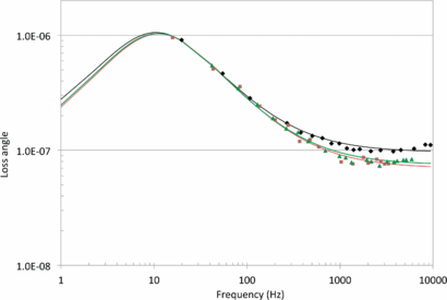
Figure 7. Measured losses for laser pulled fibers. Black diamond points show a fiber pulled without polishing the stock material. Green triangular points show a fiber pulled from stock that had been polished for 550 s. Orange square points show a fiber pulled from stock that had been polished for 3000 s. The black, green and orange lines show a fit of equation (6) to the measured losses of the unpolished, 550 s polished and 3000 s polished fibers respectively. The peak in dissipation seen just above 10 Hz is the thermoelastic damping peak frequency.
Download figure:
Standard image High-resolution image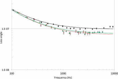
Figure 8. Close up view of fiber losses above the thermoelastic peak, in the region where losses are dominated by surface dissipation. Black diamond points are measured losses of fibers with no polish. Green triangular points are measured losses of fibers polished for 550 s. Orange square points are measured losses of fibers polished for 3000 s. The black, green and orange lines show a fit of equation (6) to the measured losses for the unpolished, 550 s polished and 3000 s polished fibers respectively.
Download figure:
Standard image High-resolution image
Table 1. Material values used for the calculation of thermoelastic losses.
| Y (N m−2) | ρ (kg m−3) | C (J kg−1 K) | κ (W m−1 K) | α (K−1) |
|---|---|---|---|---|
| 7.2 × 10¹⁰ | 2200 | 770 | 1.38 | 3.6 × 10⁻⁷ |
From these results we find that there is a small but measurable improvement in the surface loss of both polished fibers, with all measured modes seeing a reduction in loss. Using equation (2) we can calculate the value of hϕsurface, a useful quantity which allows us to compare the surface quality of fibers independent of the diameter. Table 2 shows the results for each of the three fibers. Errors for these values were calculated from the fit of the data. The unpolished laser pulled fiber gave an hϕsurface = 4.9 × 10⁻¹² m. The fiber polished for 550 s saw a reduction in loss at the level of 24%, with hϕsurface = 3.7 × 10⁻¹² m. The fiber polished for 3000 s had a reduction of approximately 31%, with hϕsurface = 3.4 × 10⁻¹² m. For comparison, previous measurements made using fibers pulled from Heraeus SUPRASIL 2 fused silica using a gas flame-pulling technique gave an hϕsurface = 5.9 × 10⁻¹² m [18]. As was described in section 1, a reduction of internal damping in the surface layer is primarily important for the horizontal component of thermal noise in the detectors. While the reduction in loss seen here is a significant percentage improvement, it is only a slight improvement in thermal noise. The fibers that are being installed in Advanced LIGO will be polished using this technique and will thus see a slight reduction in thermal noise. Considering that the surface dissipation is still several orders of magnitude higher than bulk losses in fused silica, these results may however indicate that there are still improvements that could be made to further reduce losses associated with the surface layer.
Table 2. Surface loss, hϕsurface, of laser polished fibers from fitting the loss measurements.
| Fiber 1 (no polish) | Fiber 2 (550 s polish) | Fiber 3 (3000 s polish) |
|---|---|---|
| (4.9 ± 0.3) × 10−12 m | (3.7 ± 0.4) × 10−12 m | (3.4 ± 0.3) × 10−12 m |
5. Conclusions
A method of improving the surface quality of fused silica fibers was developed. This technique involves laser polishing the stock material from which the fiber is drawn. It has been shown that this polishing significantly increases strength of the fibers, with an average breaking stress of 4.4 GPa being achieved for fibers polished for 3000 s. The technique also reduces the surface dissipation by 30%. Based on these values it should be possible to decrease the cross-sectional area of fibers used to suspend the mirrors of gravitational wave detectors, allowing a decrease in vertical bounce frequency. For the Advanced LIGO detector it would be conceivable to decrease the bounce frequency from just above 9 Hz to around 6.5 Hz, while still achieving a factor of three safety margin over the working stress. The reduction in loss seen here would in practice not give a significant improvement to the thermal noise performance of the detectors because the strain sensitivity is dependent on the square root of the suspension loss angle, making this equivalent to an improvement of 18% in strain sensitivity. Further improvement may be possible given that the surface dissipation in fused silica is approximately three orders of magnitude higher than the bulk dissipation.
Acknowledgments
We would like to thank our colleagues in the LIGO Scientific Collaboration, the GEO600 project, and the Scottish Universities Physics Alliance (SUPA) for their interest in this work. We also wish to thank the ILIAS Strega project and Leverhulme Trust for support. We are grateful for the financial support provided by the NSF in the USA and the STFC and the University of Glasgow in the UK. The LIGO Observatories were constructed by the California Institute of Technology and Massachusetts Institute of Technology with funding from the NSF under cooperative agreement PHY-9210038. The LIGO Laboratory operates under cooperative agreement PHY-0107417. STFC funding is provided under grant ST/J000361/1.