


Abstract
An optical layout of a corrected Cassegrain telescope with an aperture of 3.6 m (f/3.0) and a 2 5 field of view is proposed. The primary and secondary mirrors are standard hyperboloids; all five corrector lenses are made of fused silica and have spherical surfaces. The total length of the optical system is 4.36 m. The rms spot diameter in the "g," "r," "i" integral waveband of 0.40–0.82 μm is about 0
 3 across the flat focal surface; the D80 star diameter is about 04. Due to the low light vignetting, the effective aperture diameter reaches 3.3 m. The comparative simplicity and compactness of the optical layout allow us to consider this system promising for conducting deep sky surveys.
Export citation and abstract BibTeX RIS
1. Introduction
At the turn of the century, two main alternatives were discussed in connection with the creation of an effective system for wide-field sky tracking: a set of several telescopes of the same type with an individual effective aperture of about 1.5 m and a single telescope with an effective aperture of about 6.5 m. The first of these directions was developed in the Pan-STARRS project (Kaiser et al. 2002; Hodapp et al. 2004), whose base telescope, PS1, was commissioned in 2007; the second option is the Large Synoptic Survey Telescope (LSST; Angel et al. 2000; Starr et al. 2002; Tyson & Wolff 2002; Ivezić et al. 2019), the installation of which is nearing completion. The angular field sizes of these telescopes are, respectively, 30 and 35; the focal ratio ϕ ≡ F/D of PS1 is 4.4, whereas LSST has an extremely high speed of ϕ = 1.23 with an entrance pupil diameter of 8.4 m. The main advantages of the first direction are the simplicity of the optical system, the ease of matching it with modern radiation detectors, and the reliability of multiple identification of objects, while the second concept focuses on the depth of survey.
The factors mentioned above are quite weighty, and yet systems with an intermediate aperture of about 3.5–4.5 m and a flat field of 25–30 seem closer to the optimum. The key factor here is related to the matching of the resolving power of the optical system with the discrete structure of current radiation detectors. For survey telescopes, a scale of 3–4 pixels per second of arc is sufficient, which implies a telescope effective focal length of about 9–12 m when the pixel size is about 15 μm. The corresponding focal ratios in the range of 2.8–3.5 make it possible to create a moderate-sized telescope still relatively simple and cheap, whereas its efficiency is noticeably higher than that of a telescope with an aperture of 2 m. Probably such considerations were meant when converting the 4 m Blanco telescope into a Dark Energy Camera (DECam; Flaugher et al. 2015). It seems important that the efficiency of a set of several different wide-field telescopes of moderate size, optimized as a whole, approaches the efficiency of a highly complex LSST.
As for the optical layout of the 4 m class telescope, a lens corrector seems preferable either in primary focus, as was done in DECam, or in a secondary focus, as is the case of Pan-STARRS. All-spherical lens correctors of one glass for a prime focus of 4 m telescopes allow for the implementation of a flat field of sub-arcsec quality with a diameter up to 3° (Terebizh 2004; Saunders et al. 2014), but such telescopes are long, which entails the need for a large dome and the increased cost of the entire project, especially in its multitelescope version.
The latter circumstance induces a search for a solution in the class of corrected Cassegrain systems. Among the systems of this type, the One Degree Imager of the WIYN Observatory (WIYN ODI) and T250 telescopes can be distinguished. The aperture of the first of them is 3.5 m and a flat field is close to 1° (Harbeck et al. 2018), whereas these parameters are, respectively, 2.5 m and 30 for the second telescope. According to Cenarro et al. (2010) and Benitez et al. (2014), T250 is an f/3.6 two-mirror Cassegrain telescope equipped with a lens field corrector. The telescope provides an image quality of D80 ≤ 20 μm (045) in the waveband 0.33–1.1 μm. For all we know, only a cursory description of the optical layout of the T250 was published. The abovementioned paper (Cenarro et al. 2010) states: "The primary and secondary mirrors have an hyperbolic aspheric surface," whereas the field corrector "...consists of 3 lenses of fused silica with aspheric surfaces and diameters in the range 500–600 mm."
Obviously, in order to compete with the prime-focus correctors, it would be desirable to have a reliable corrected Cassegrain system with an aperture diameter no less than 3.5 m and a field of 25–30. In this note, such an attempt is presented in relation to the 3.6 m telescope with a field of 25 in diameter.
2. The Design
Figure 1 shows the optical layout of the proposed design of VT-137q and its main characteristics are given in Table 1. As one can see, the use of a Cassegrain system with a simple five-lens corrector provides a more than two-fold reduction in the length of the telescope compared to a prime-focus system.
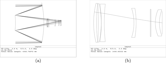
Figure 1. (a) Optical layout of the 3.6 m,  design of VT-137q with a field of 25 in diameter. The flat filter is also shown. (b) Enlarged all-spherical five-lens corrector layout. The corrector itself has a slight negative optical power at a speed of f/13.3; the last lens serves as a detector window.
Download figure:
Standard image High-resolution imageTable 1. Basic Characteristics of the VT-137q Design
| Parameter | Value |
|---|---|
| Entrance pupil diameter | 3600 mm |
| Effective focal length at 0.65 μm | 10,800 mm (f/3.0) |
| Scale in the image plane | 52.4 μm arcsec−1 |
| Field-of-view diameter | 25 (flat field of 474 mm) |
| Primary spectral waveband | 0.40–0.82 μm |
| Fraction of unvignetted light | 0.839 across the field |
| Linear obscuration | 0.40 |
| Effective aperture diameter | 3297 mm |
| Maximum distortion at 0.65 μm | 0.64% |
| rms spot diameter in the integral light | |
| of g-i bands, center–edge | 13.3–17.3 μm (025–033) |
| Diameter of a circle containing 80% of energy | |
| in a star image (D80), center–edge | |
| Integral light | 18.6–21.6 μm (035–041) |
| g band | 16.0–21.5 μm (031–041) |
| r band | 12.1–19.8 μm (023–038) |
| i band | 13.2–23.5 μm (025–045) |
| Number of lenses | 5 |
| Maximum lens diameter | 800 mm |
| Lens material | All of fused silica |
| Lens surfaces | All spheres |
| Total length of the optical system | 4363 mm |
Download table as: ASCIITypeset image
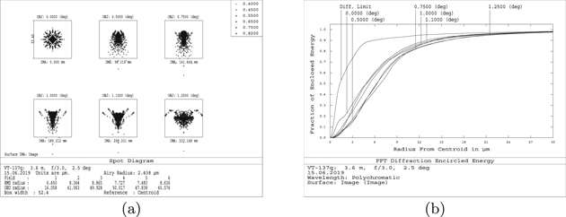
The system was optimized for the spectral range of 0.40–0.82 μm, which includes the g, r, and i wavebands. The rms spot diameter in the integral spectral range is about 03; the D80 star diameter is about 04 across the flat field of view (Figure 2). The information concerning the image quality in individual bands is given in Table 1. Note that image quality remains feasible outside the range of optimization, while the use of fused silica provides good transparency of optics.
Figure 2. (a) Spot diagrams for the VT-137q design in the integral waveband 0.40–0.82 μm; the box width is 52.4 μm (10). (b) Polychromatic encircled energy diagram in the integral waveband for VT-137q. The curves correspond successively to the diffraction limit, the axial beam, and the field angles of 05, 075, 10, 11, and 125.
Download figure:
Standard image High-resolution image
To simplify the corrector, and most importantly, to reduce the vignetting of light, the aperture stop is placed on the secondary mirror. In this way, it was possible to reduce the size of the secondary mirror, to increase the fraction of unvignetted rays to 0.84, and thereby ensure an effective aperture diameter of almost 3.3 m. Although the diameter of the primary mirror increases with this stop position up to 3844 mm, the above advantages are more substantial.
The system uses only the so-called standard forms of optical surfaces, i.e., the conic sections: both mirrors are hyperboloids, while all surfaces of the lens corrector are spheres. Table 2 gives a complete description of the optical layout.
Table 2.
VT-137q Design with 3.6 m Aperture and 25 Field
| Surf. | Comments | R0 | T | Glass | D |
|---|---|---|---|---|---|
| No. | (mm) | (mm) | (mm) | ||
| 1 | Obscuration |

|
2699.141 | ⋯ | 1440.0 |
| 2 | Primary | −8994.221 | −2699.141 | Mirror | 3843.6 |
| 3 | Secondary | −6147.061 | 2956.316 | Mirror | 1439.3 |
| 4 | Lens 1 | 1676.528 | 60.0 | FS | 800.0 |
| 5 | 3493.014 | 37.23024 | ⋯ | 789.2 | |
| 6 | Lens 2 | −7834.449 | 60.0 | FS | 786.5 |
| 7 | −1764.076 | 0.250 | ⋯ | 780.6 | |
| 8 | Lens 3 | −2684.184 | 61.0 | FS | 773.3 |
| 9 | 3527.065 | 608.4991 | ⋯ | 747.2 | |
| 10 | Lens 4 | −943.2483 | 45.0 | FS | 597.7 |
| 11 | −1800.737 | 289.6941 | ⋯ | 598.5 | |
| 12 | Filter |

|
15.0 | N-BK7 | 559.0 |
| 13 |

|
88.63177 | ⋯ | 557.7 | |
| 14 | Lens 5 | 669.9608 | 84.0 | FS | 540.5 |
| 15 | 727.1139 | 57.14807 | ⋯ | 515.2 | |
| 16 | Image |

|
⋯ | ⋯ | 474.3 |
Note. R0: the paraxial curvature radius; T: axial thickness to the following surface; D: surface diameter within the light beam; FS: fused silica. The stop is located on the secondary mirror. Conic constants of the primary and secondary mirrors are, respectively, −1.309746 and −9.75035; all other surfaces are spheres. Lens 5 is a detector window.
Download table as: ASCIITypeset image
The implementation of a flat focal surface is achieved mainly with the help of the latest corrector lens, which follows the classical Piazzi–Smith tradition. I also use the latest lens as a detector window. This possibility, which was first proposed, apparently, by B. Delabre (2002, not published) has become widespread in recent decades (Terebizh 2004; Flaugher et al. 2015).
Saunders et al. (2014) drew attention to another positive aspect of using a purely spherical lens corrector. Namely, the correction of atmospheric dispersion can be realized by a small mutual shift of a pair of spherical lenses perpendicular to the optical axis. Recall that in the presence of aspheric surfaces, it is necessary to introduce into the system a pair of additional optical elements made of special glass.
In regards to the hyperbolic mirrors, the main difficulty in making of aspheric optical surfaces is not related to the magnitude of the deviation from a nearest sphere but rather to the asphericity gradient G(r)—the rate at which the deviation changes along the radial coordinate. The function G(r) can be found numerically by means of modern programs of optical calculations, whereas an approximate formula

is useful for estimating the maximum radial asphericity gradient in a case of a standard surface of the diameter D, the paraxial curvature radius R0, and the conic constant b (Terebizh 2011, 2016). For example, Gmax ≈ 0.54 μm mm−1 for a secondary mirror of the Hubble Space Telescope (HST), i.e., the deviation of its surface from the nearest sphere increases by 0.54 μm with the increase of the distance from the mirror's center by 1 mm (see Burrows 1990 for the HST data summary).
In my case, Equation (1) gives Gmax about 3.19 μm mm−1 and 3.91 μm mm−1 for the primary and secondary mirrors, respectively. These values are quite consistent with the capabilities of modern technology, which reach nearly 20 μm mm−1 (Flaugher et al. 2015).
3. Conclusions
To illustrate the effectiveness of the design with a field of 25, suppose that the set of detectors fills the entire visible focal plane with a diameter of 474 mm, the exposure time Te is 20 s, and the dead time, Td, corresponding to reading the data and redirecting the telescope is 5 s. Then, the survey speed is  deg2 s−1. This means that nearly 14 hr is needed to cover the sky area of 104 deg2, which is a little smaller than the entire hemisphere visible above the horizon and free of absorption in the Milky Way and Earth's light pollution at large zenith angles. The corresponding limiting magnitude at typical conditions of observations is
  for the integrated waveband of 0.40–0.82 μm, the detector quantum efficiency of 0.85 photoevents/photon, and the boundary signal-to-noise ratio S/N = 7.
When compacting a telescope by installing a secondary mirror into a one-mirror system, we get not only this additional optical element, but also the need to make much more complex optical surfaces of both mirrors compared to the original primary one. Another consequence of this step is that the secondary-focus corrector allows us to reach a somewhat smaller field of view. On the other hand, besides compactness, some attractive features are inherent in the corrected Cassegrain system. In particular, let us compare the size and weight of lens correctors in the prime and secondary foci of similar telescopes. The light diameter of the first of five DECam corrector lenses with a field of 22 is 932 mm and the total mass of the lenses inside the light beam is 335 kg (Flaugher et al. 2015). These values are 800 mm and 263 kg, respectively, for the design considered here with a 10% less aperture, but with a larger field of 25. It should also be noted that the location of the corrector in the secondary focus is more preferable from a mechanics point of view. All these factors, as well as those that seem less important at first sight, should be accounted for in the choice of a telescope optical layout.