

Abstract
In recent years, one of the most important challenges of the 21st century is to satisfy the ever-increasing world's energy demand. Many efforts are being undertaken to find alternative renewable energy sources, which ideally should outcompete fossil fuel use in all its aspects. In this respect, photo-assisted microbial bioelectrochemical cells (MBECs) in which the reduction of water to hydrogen takes place have been of considerable interest in recent years. Two categories of such systems have been investigated: MBECs with a semiconductor photocathode or photoanode, and hybrid systems, in which an MBEC cell with dark electrodes is coupled to an electrochemical photovoltaic cell. A common denominator of all these systems is the need of microorganisms at the anode, the action of which results in the generation of an electron flow by organic matter oxidation. The aim of this review is to describe the general working principles, with respect to both biochemical and electrochemical aspects, and the performance of various categories of hydrogen-generating photo-assisted MBECs.
Export citation and abstract BibTeX RIS

Original content from this work may be used under the terms of the Creative Commons Attribution 4.0 license. Any further distribution of this work must maintain attribution to the author(s) and the title of the work, journal citation and DOI.
1. Introduction to microbial bioelectrochemical cells (MBECs)
MBECs known as microbial fuel cells (MFCs) and microbial electrolysis cells (MECs) have been extensively studied for the generation of electricity (MFCs), chemicals (MECs), and the remediation of effluent water (MECs or MFCs) (Scott and Yu 2016). A general MEC configuration is shown in figure 1. Among them, MBECs incorporating semiconductor photoelectrodes are new subjects in the research of bioelectric systems. They can be termed microbial photoelectrochemical fuel cells (MPFCs), and microbial photoelectrolysis cells (MPECs). At first, an introduction to MBECs operating with dark (in the sense of not needing light for their operation) electrodes, in the sense of not needing light for their operation, is presented. The difference between an MFC and an MEC consists in the final product, the first is electricity and the second one or more chemical products, hydrogen in the context of the present publication. Their operation is based most of the time on a bio-anode populated by microorganisms immersed in a cultivation medium which feeds them. These systems use electrogenic microorganisms in the role of a catalyst for organic matter oxidation. Since the respiration of these microorganisms is based on outside electron acceptors, they are defined as exoelectrogenic microorganisms. Beside an electron flux, they also generate by oxidation a concomitant proton flux that has to leave the microbes at the same time. The anode (electrochemical oxidation) compartment needs anaerobic conditions in a way enabling microorganisms to transfer electrons to the electrode. Furthermore, an oxidant species has to be reduced at the cathode. In MFCs, oxygen is usually used for this purpose. In an MEC, chemicals are produced with the possibility of using a lower external voltage than in a conventional electrochemical cell (Liu et al 2010). For example, if cathodic and anodic overvoltage (overpotential) are not considered, only 0.13 V are needed, corresponding to the electromotive force of the hydrogen evolution reaction (HER) in the case of acetate as substrate oxidatively metabolized by microorganisms, as compared to 1.23 V required for the water splitting process under ambient conditions with all species in their standard state. The development and the new research perspectives of new BEC versions with higher performances using new electrode materials are reported in this review.

Figure 1. Scheme of a microbial electrolysis cell producing hydrogen.
Download figure:
Standard image High-resolution imageSystems for solar hydrogen production by water splitting can be classified in three general categories: thermochemical, photobiological, and photocatalytic (Liao et al 2012). The thermochemical hydrogen generation is based on the fact that at a sufficiently high temperature, above 1000 K, the water splitting reaction becomes thermodynamically spontaneous, with the equilibrium shifting in favour of the hydrogen evolution to a larger extent with increasing temperatures. Both photobiological and photocatalytic methods are quantum solar method, based on the generation of electron–hole pairs upon irradiation with photons of energy exceeding a certain threshold. Photobiological methods are based on the excitation of whole photosynthetic organisms, green algae or photobacteria. Photocatalytic methods are based on the excitation of photoactive inorganic or organic compounds, including these extracted from microorganisms and used in vitro. Among photocatalytic systems for hydrogen generation, photoelectrochemical cells have attracting considerable interest. Among them, the MPEC based on interfacing microbial reactions to the primary abiotic photoexcitation process is a newcomer, having attracted limited interest up to the present time but holding considerable interest for future developments (Fischer 2018).
In the present publication, hydrogen-evolving MPECs will be described. As regards MPFCs and MPECs with alternative uses, it should be noted that the photocatalysts and microbial reactions used in them could be, in principle, applicable to hydrogen-evolving MPECs as well; therefore, the related literature should be consulted. Information about MPFC is available in a number of publications (Lu et al 2010, Du et al 2014, Sun et al 2015, Kim et al 2018b, Guo et al 2019, Jia et al 2019) and in the review of Fischer (2018). Other types of MPECs studies of interest are these discussing water effluent remediation without hydrogen evolution (Hou et al 2020a, 2020b), the reduction of carbon dioxide to methane or carbon monoxide (Fu et al 2018, Kim et al 2018b, Lu et al 2010, Xiao et al 2020a, 2020b) as well as a number devoted to fundamental photoelectrochemical studies of microbial systems not related to a particular application (Qian et al 2010, Qian et al 2014, Feng et al 2016, Liang et al 2016a, Zhu et al 2017). MECs for carbon dioxide reduction or carbon monoxide, the latter a component of syngas (mixture with H2), have been extensively studied; details are available in the reviews by Li and Liao (2013) and Villano et al (2010). However, research on their photoelectrochemical analogues has been rather limited. Interesting insights in the coupling of CO2-reducing MECs to solid-state solar cells are provided by Nevin et al (2010). The discussion of MEC systems incorporating solid-state, non-photoelectrochemical solar cells is beyond the scope of the present review.
1.1. Reactors and design
Different MFC/MEC architectures are used that comprise single and double-chambered reactors. The utilization of one type instead of another depends on the purpose (Logan et al 2006). The earlier reactors were often composed of two bottles (one per each half cell), which were connected by a tube with a cation-exchange membrane (CEM). Usually, an ion-exchange membrane (IEM) could allow the passage of either cations or anions (anion-exchange membrane). The CEM permits protons or other cations passing to the cathode, thereby avoiding oxygen diffusion to the anode (Min et al 2005). For MFC, the double-chamber configuration could be the preferred solution.
The single-chamber configuration is preferred in MECs, since an IEM may not be absolutely needed (Bond et al 2002, Kim et al 2002, Min and Logan 2004). In this case, the reactor can have different architectures, but the essential feature is that anode and cathode are immersed in the same electrochemical solution (Kim et al 2007, Call and Logan 2008, Hu et al 2008). This configuration decreases the internal resistance by eliminating that across the membrane. For this reason, in the case of a stipulated current density, e.g. at the cathode, the applied voltage is expected to be reduced, resulting to energy savings. Alternatively, in the case of a stipulated cell voltage, the current density, and consequently the rate of hydrogen generation, is expected to be enhanced. Nevertheless, some researchers prefer the double-chamber configuration, because the compartments separation avoids the uncontrolled mixing of chemicals produced by the cathode and the anode, as in the case of gaseous product generation at the cathode or of electroactive compounds generated by effluent water cleaning from hazardous chemicals. In the case of gas generation like hydrogen or methane in MECs, a membrane prevents the diffusion and reoxidation of the gaseous product at the anode, therefore avoiding the diminishment of the faradaic yield for the desired product. A disadvantage of the membrane in MECs is that a substantial pH difference occurs. The reason is that the membrane is not only permeable to protons, but also to other cations. The concentration of cations such as Na+, K+, Ca2+ and Mg2+ in microbial cultures is usually higher than that of protons, and these cations are transferred faster to the cathode, resulting to a pH gradient (Rozendal et al 2006, 2007, Kim et al 2007).
1.2. Exoelectrogenic microorganisms in bio-electrochemical cells: an overview
Bacteria transfer electrons to the anode by an either direct or indirect mechanism, which usually depends on the microorganism properties. Three mechanisms are essentially known: transfer by using a specific mediator (Rabaey et al 2004, 2005); nanowires in bacteria membranes (Reguera et al 2005, Gorby et al 2006); direct membrane-protein associated transfer (Bond and Lovley 2003).
The simplest way is the direct electron transfer from the bacterium membrane to the electrode. In this case, the most representative microorganisms that use this mechanism are: Shewanella (Bretschger et al 2007), Rhodoferax ferrireducens (Chaudhuri et al 2003), and Geobacter (Bond et al 2002). These bacteria transfer electrons by outer membrane cytochromes (Myers and Myers 1992).
A second way to transfer electrons consists in using one or more redox mediators or shuttles (Rabaey et al 2005, Rabaey and Verstraete 2005), which is able to accept electrons from the substrate at close proximity to the bacterium membrane and to the oxidase itself and then transfer them to the anode electrode. The mediators are directly produced by electrogenic microorganisms.
Other microorganisms, like Shewanella, may produce specific pili nanowires, which connect the same species of bacteria. Finally, they transfer electrons to the anode (or to a final electron acceptor) using these conductive structures, in the presence of an electron-accepting mediator (Reguera et al 2005, Gorby et al 2006). Furthermore, pili can equally connect even different species to each other (Gorby et al 2006). This system may enhance electron transfer from bacteria to electron acceptor without direct contact between the cell and the acceptor or the use of an electron shuttle. Sometimes, microorganisms are able to use more than a single electron transfer system: Shewanella can transfer electrons by means of a self-produced mediator, for example flavin mononucleotide (FMN) and riboflavin, to another mediator (Bond and Lovley 2005, Marsili et al 2008, von Canstein et al 2008). Such microorganisms are able to transfer electrons in this way because they can survive in anaerobic conditions, using other final electron acceptors, like metal ions. For instance, Fe3+ may be reduced by bacteria to Fe2+ (Logan 2009).
An MEC may work using either a pure or a mixed culture. The first solution could be of interest when researchers have to understand the operation of a BEC for a specific bacterium strain: it is usually used for research purposes. Mixed cultures are more widespread in application-oriented systems; in this case, a consortium of microbial strains constitute a biofilm on the anode and the electron transfer is guaranteed by the aforementioned mechanisms. A high number of strains in a mixed culture enhances the bioanode diversity composition (Bond et al 2002, Phung et al 2004). For instance, a specific strain, which is able to produce redox mediators, may provide them to other microorganisms (which do not produce the mediator by themselves) of the consortium, thereby enhancing the system efficiency (Rabaey and Verstraete 2005). Nevertheless, BEC performances may change because of the interplay of different parameters: microorganism metabolism, electron transfer efficiency, membrane ohmic resistance (if any), electrolyte ohmic resistance, and cathode efficiency to reduce an oxidant species (Rabaey et al 2004). The presence of a bacterium strain in a reactor may change due to its architecture and the conditions used (Logan and Regan 2006). BEC research have demonstrated that a bioanode acclimatization may occur using different sources, as marine sediment (Reimers et al 2001, Tender et al 2002) and wastewater or sewage sludge (Kim et al 2004, Pant et al 2010).
In recent years, researchers try to develop more efficient systems to produce more energy in the case of MFC or larger quantity of chemicals with MBECs. The anode is the engine of an MBEC (MFC and MEC): microorganisms able to produce electrons live there. Bioanode performances may be improved overcoming limiting factors in the system. Different parameters, such as pH, medium composition and anode potential influence the microorganism concentration, biofilm conditions and electron transfer rate. Many efforts in research have focused on studies aiming to enhance the performances of the bioanode in order to ensure a higher system efficiency (Pham et al 2009). It is possible to reach this aim by changing several relevant parameters in the two compartments. This concerns acclimatization period and substrate used, and type of electrode materials. For instance, in the case of a system works with an electrode composed of diverse carbon or metal structures and the kind of surface treatment, it was found that carbon nanoparticles on the anode surface enhanced biocompatibility and performance (Hou et al 2014). Electrode design is crucial because it enables to reduce the overvoltage in an MEC, which is a central issue in hydrogen production, where a power supply has usually to be employed. The enhanced performances are possible by using innovative materials, such as nickel alloys (Hu et al 2008) and stainless steel (Call et al 2009), which enhance the catalytic performances (Selembo et al 2009), or semiconductor photoelectrodes. Each solution described has disadvantages; for instance, carbon-based electrodes are expensive and semiconductors are not always stable (Guo et al 2015).
2. Photo-assisted MECs with metallic-conductivity electrodes
A way to enhance the performance of MBECs is by using systems which are able to produce electrical current, if exposed to light. A number of studies demonstrated a better performance, as compared to the case in absence of light, in several system configurations. In one of them, the MBEC operation is based on light harvesting by photosynthetic organisms (figure 2) in the anode compartment, which interact with electrochemically active bacteria attached in the anode electrode, resulting to organic matter production (Strik et al 2011). The cathode reaction is oxygen reduction. In such a kind of system, a microorganism selection occurs. For instance, microorganisms like Geobacter have exclusively an anaerobic metabolism, consequently they do not survive in the presence of photosynthetic organisms, which produce oxygen (Blatter et al 2020). The alternative option of hydrogen evolution at the cathode, instead of the oxygen reduction, can also be envisaged. Such systems are often denoted as photobioelectrochemical cells. However, the same term can be also used for microbial MBESs systems based on the photoexcitation of semiconductor electrodes rather than of the microorganisms themselves. The latter systems are described in the following sections.

Figure 2. General scheme of a microbial solar cell involving the following processes: (a) photosynthesis, photosynthetic organisms. (b) Organic matter transport to the anode. (c) Anodic organic matter oxidation by electrochemically active microorganisms. (d) Cathodic reduction of oxygen to water (scheme based on Strik et al (2011)). Reprinted from [Strik et al (2011)], Copyright (2011), with permission from Elsevier.
Download figure:
Standard image High-resolution image
Figure 3. Microbial photoelectrolysis cell adapted from Chen et al (2013). CB, VB are respective initials for conduction band and valence band. Solid and empty dots at the photocathode are the photogenerated electrons and holes. The black dots at the dark bioanode represent the electrons generated by microorganisms. Reprinted from [Chen et al (2013b)], Copyright (2013), with permission from Elsevier.
Download figure:
Standard image High-resolution image3. Introduction to electrolytic photoelectrochemical cells
3.1. General concepts
As electrolytic photoelectrochemical cells, or photoelectrolysis cells, will be denoted in this section cells comprising one or two photoexcited semiconductor–electrolyte interfaces in which different reactions take place at the cathode and anode so that a net chemical reaction takes place. These cells are contrasted to electrochemical photovoltaic cells converting light to electricity without any net change in the electrolyte, with the species being oxidized at the anode undergoing reduction at the cathode, such as the dye-sensitized solar cell (DSSC) mentioned in the previous section. In general, photoelectrolysis cells are classified either as photoelectrosynthetic or photocatalytic cells, depending on whether the overall reaction is endoergic (thermodynamically non-spontaneous) or exoergic (thermodynamically spontaneous). In the case of photoelectrosynthetic cells, stored energy is equal to the Gibbs free energy of the overall reaction. However, in the photoelectrolysis hydrogen-evolving MPEC cells considered in the present publication the stored energy corresponds to the endoergic water decomposition reaction

with oxygen originating from the atmosphere.
The reaction at the anode is not of interest to energy storage, with the resulting electrolyte solution after oxidation either being discarded or undergoing, in the case of water effluent remediation, further chemical or biochemical purification.
In the simplest MPEC configuration operating under short circuit with one photoelectrode, the energy storage efficiency  for hydrogen generation is

with:
I current (A),
 faradaic efficiency,
F Faraday constant (charge per mole of electrons)(C mol−1),
n number of electrons for each of the half reactions constituting the overall chemical reaction,
 the Gibbs free energy of the overall chemical storage reaction (J mol−1),
 irradiance (W m−2).
If the water decomposition reaction is formulated according to equation (1), it is n
= 4 with  equal to 4F (1.23 V) or 474.3 kJ mol−1.
It is also possible to have simultaneous solar energy storage and generation of electrical energy if an external resistance  is inserted across the cell, corresponding to electric power generation equal to
  . In this case the total energy conversion efficiency is

A series of pioneering water splitting experiments using a semiconductor electrode were conducted by Honda, Fujishima et al in the 1970s (Fujishima and Honda 1971, 1972, Fujishima et al 1975b) based on a n-TiO2 photoelectrode with a dark Pt counter electrode, with the semiconductor exposition to the sunlight enabling electron excitation from the valence to the conductive band, generating an electron–hole couple on TiO2. Given its large bandgap energy (EBG= 3.0 eV), only UV light could be adsorbed. Since UV light represents only <5% of the solar spectrum, the energy conversion efficiency of systems based on TiO2 is low, so that research efforts have been directed toward the development of materials which are able to adsorb visible light in an efficient and high-performance way. This means not only that the EG is more suitable for adsorption of a large fraction of solar photons but also that the deleterious recombination of the photogenerated electrons and holes, resulting to the evolution of heat or fluorescent radiation, is not important.
Different semiconductors may either oxidize or reduce water to gaseous oxygen and gaseous hydrogen, respectively; some may carry out both reactions, depending on the EBG as well as the position of the valence and conduction band edges at the electrode surface. The needed applied thermodynamic voltage for water splitting in photoelectrochemical cells corresponds to 1.23 V under standard conditions: if anodic and cathodic overvoltages are considered, at least 1.7–1.9 V are needed (Chen et al 2012). A material eligible such as photo-electrode semiconductor needs to have the additional feature of being resistant to corrosion in the dark and, in particular, under irradiation (photocorrosion). To avoid the latter problem, during light exposition the electrons or holes generated in the semiconductor does not have to react with the semiconductor instead of participating to useful electrochemical reactions.
A number of semiconductors used in microbial photoelectrochemical cells is presented in table 1. As discussed in the following section, the positions of the band edges are expressed in energy units (eV) rather than, as it is often the case for photoelectrochemistry publications, in equivalent electric potential (V) units.
Table 1. Semiconductors reported in literature studies of microbial photoelectrochemical cells. EBG: bandgap energy. ECS and EVS: conduction and valence band edge. RHE: reversible hydrogen electrode.
| Semiconductor | EG (eV) | ECS (eV) vs RHE | EVS (eV) vs RHE | |
|---|---|---|---|---|
| 1 | CaFe2O4 (p) | 1.9 | 0.6 | 1.3 |
| 2 | CdS (n, p) | 2.4 | 0.2 | −2.2 |
| 3 | Cu2O (p) | 2.0 | 0.7 | 1.3 |
| 4 | CuO (p) | 1.7 | 0.8 | −0.9 |
| 5 | Fe2O3 (n) | 2.0 | −0.5 | −2.5 |
| 6 | Si (n, p) | 1.1 | 0.8 | −0.3 |
| 7 | TiO2 (n)—anatase | 3.2 | 0.1, 0.2 | −3.1, 3.0 |
| 8 | TiO2 (n)—rutile | 3.0 | 0.0, 0.1 | 3.0, 2.9 |
| 9 | WO3 (n) | 2.4 | −0.4 | 2.8 |
Notes. 1 Sivula and van de Krol (2016). 2 Grimes et al (2008), at pH = 7. 3 Paracchino et al (2011). 4 Hardee and Bard (1977). 5 Sivula and van de Krol (2016), Lindgren et al (2002). 6 van der Valle and Neugebauer (2003). 7 Hengerer et al (2000), single crystal anatase, ECS = 0.1 eV, both (101) and (111) faces; Rothenberger et al (1992), polycrystalline anatase ECS = 0.2 eV. 8 Nakamura (2005), single crystal rutile, ECS = 0.0 eV for (110) face and 0.1 eV for (100) face. 9 Alexander et al (2008).
For the principles of semiconductor photoelectrochemistry, details of various electrode materials, and experimental methods the books by Myamlin and Pleskov (1967), Grätzel (1983), Schiavello (1985), Pleskov and Gurevich (1986), Finklea (1988), Sato (1998), Grimes et al (2008), Rajeshwar (2008), van de Krol and Grätzel (2012), Chen et al (2013a), Giménez and Bisquert (2016), Sharon (2016) can be consulted.
4. Photoelectrode materials
A photoelectrochemical process, like the water decomposition reaction or the oxidation of organic compounds coupled to hydrogen evolution, can be divided into three steps. The first is photon adsorption, which enables electrons–holes couple generation in the semiconductor. The second is charge separation, which depends on the semiconductors crystalline structure (the better its quality, the lower recombination probability); the last is the reaction of the photogenerated minority carrier on the semiconductor surface.
The main semiconductor photoelectrode features is the amplitude of the EG and the valence and conduction band edges EC(S) and EV(S) with respect to the redox Fermi level of the redox species Ox/Red interacting with the photoelectrode.
The redox Fermi level EF (Ox/Red) for a redox system Ox/Red is defined as the Fermi level (electrochemical potential) of electrons in a metal or semiconductor electrode equilibrating with Ox/Red or, equivalently, as the electrochemical potential of solvated electrons in the electrolyte equilibrating with Ox/Red. EF (Ox/Red) can be defined vs vacuum (EF/VAC (Ox/Red)). Alternatively, EF (Ox/Red) can be defined vs a reference redox system (EF/REF (Ox/Red)) i.e. vs the electrons in an electrode, or the solvated electrons in the electrolyte, equilibrating with the reference redox system. The most used reference electrode (REF) for aqueous systems is the standard hydrogen electrode (SHE) corresponding to the redox system H+/H2 reaction corresponding to unit hydrogen ion activity (pH = 0) and the standard ambient absolute temperature and pressure (SATP) condition of T = 298 K and p(H2) = 1 bar. The corresponding half reaction is

 are related to the electrode potential
  , commonly used in electrochemistry, as

where  is the elementary (proton) charge.
In the discussions of electrochemical energetics of the present review, redox Fermi levels will be used in preference to electrode potentials.
In place of the SHE, other REF, e.g. the saturated calomel electrode or the silver chloride REF, can be used so that in the last equations EF/SHE can be replaced by EF/REF.
If for Ox/Red all species are in their standard activity at a specified T, then EREF and EF/REF are the standard electrode potential  and the standard redox Fermi level
  . Tabulated
  data are usually given at T= 298.15 K. If for Ox/Red all species, apart from H+, are in their standard activity, then EF/REF is termed apparent standard apparent electrode potential
  and standard apparent redox Fermi level
  corresponding to the particular pH.
In the case of the SHE chosen as REF, it is for the H+/H2 reaction at T = 298.15 K

For the O2/H2O, H+ corresponding to the half-reaction

it is

The general oxidation reaction of an organic compound containing H, O, and N, can be formulated as
where z is the charge of the compound. In the case of z = 0, the dependence of standard apparent redox Fermi level is similar to that for the H+/H2 and O2/H2O, H+ according to the equation

An example of the above reaction scheme is the oxidation of acetate to carbon dioxide, of interest to MPEC applications according to

for which

Alternatively, the above reaction can be reformulated with bicarbonate as product, according to the reaction

deviating from scheme 9 for which

For several oxide semiconductors the dependence of EC(S)/SHE and  vs pH is similar to the dependence of the redox Fermi level for the hydrogen and oxygen redox couples. In this respect, at T = 298.15 K (Nozik 1978, Pleskov and Gurevich 1986). In this respect,


For several oxide semiconductors the dependence of EC(S)/SHE and  vs pH is similar to the dependence of the redox Fermi level for the hydrogen and oxygen redox couples. In this respect, at T = 298.15 K (Nozik 1978, Pleskov and Gurevich 1986)

and

EC(S)/SHE and EV(S)/SHE can be measured by several experimental approaches.
At a semiconductor photocathode (PCAT) the overvoltage  for a photoelectrochemical reaction is determined on the basis of the quasi-Fermi level
  of photogenerated electrons as

where is the proton electric charge. The above equation is analogous to that for a dark electrode with metallic conductivity. If  is the Fermi level of electrons, it is

The upper limit of  is
is  . Therefore, the limiting cathodic overvoltage
  at the photoelectrode is

In the case of the HER, since both  and
and  shift upward upon a pH change to the same extent,
  is pH-independent.
Similarly, for a semiconductor photoanode the overvoltage  for a photoelectrochemical reaction is determined on the basis of the quasi-Fermi level
  corresponding to photogenerated holes as

The lower limit of  is
is  . Therefore, the limiting anodic overvoltage
  at the photoelectrode is

Since both  and
and  shift upward upon a pH change to the same extent,
  is pH-independent. The situation is similar for the overvoltage of organic reaction (11) for uncharged species.
Usually for a p-type oxide  lies sufficiently above
  . However, it should be noted that the band levels are in a good position for the reaction taking place, quite often a co-catalyst has to be present due to the fact that the HER is kinetically slow. Therefore, it may be necessary for the semiconductor PCAT to be coated by an electrocatalyst. In recent years, a number of no-noble earth-abundant metals and metal alloys are attracting a lot of interest as hydrogen and oxygen electrocatalysts. Further information about the principles of HER electrocatalysis is provided by Trasatti (1972), Enyo (1983), Zou and Zhang (2015), Eftekhari (2017), Yu et al (2019, 2020), Zhu et al (2020), Wang et al (2021a, 2021b).
As regards the direction of irradiation, the usual situation for photoelectrolysis cells is for the light to impinge from the electrolyte side of the interface. This scheme is termed electrolyte–electrode (EE) irradiation (Lindquist et al 1983). The alternative option of irradiation from the substrate side, is termed substrate–electrode (SE) irradiation. This requires a photoelectrode of sufficient transparency. Apart from some cases of photoelectrolysis cells requiring SE irradiation, this is the preferred method of irradiation for DSSCs based on a dye adsorbed on porous electrodes: this type of electrochemical photovoltaic cell will be considered later with respect to hybrid photovoltaic, MEC systems (section 5).
4.1. P-cuprous oxide (Cu2O)
Cu2O is a p-type semiconductor and one of the most used for hydrogen evolution, with a EBG of 2 eV bias. Its conductive band, at 0.7 eV/RHE, lies above the apparent redox Fermi level of H+/H2O (Paracchino et al 2011). It can be produced in several ways: electrodeposition (Siripala et al 2003), sputtering and thermal oxidation. A photoelectrode made with this semiconductor, could produce up to −7.6 mA cm−2 at 0 V vs RHE (Paracchino et al 2011), during an air mass (AM) 1.5G (Global, it refers to the light coming from an angle −48° from the vertical, Bolton et al 1985) sunlight exposition, with the photoelectrode immersed in a 1 M Na2SO4 solution. This semiconductor has a solar to hydrogen theoretical efficiency of 18% with one sun light exposition (Paracchino et al 2011). Despite its advantageous features, the bare semiconductor is liable to poor stability and photo-corrosion in aqueous solutions, as shown in Gerischer (1977):

Different studies showed that covering the Cu2O layer with other superficial protective layers, avoiding electrolyte contact, photo-corrosion was avoided (Wang et al 2013). When the semiconductor is covered by a protective layer, the overvoltage needed for the HER increases, to limit this issue a nickel or ruthenium co-catalyst is usually needed. Effective protection is provided by layers of Al-doped ZnO (AZO) and TiO2 deposited by atomic layer deposition (ALD), as discussed by Paracchino et al (2011). The configuration of the multilayer system described by these authors is

with an Au layer deposited on transparent conducting oxide (TCO) glass serving as electrodeposition substrate, and a thin Pt layer serving as electrocatalyst for H2 evolution. The light impinges from the electrolyte side of the interface. This scheme is termed EE irradiation (Lindquist et al 1983) and for photoelectrolytic cells this is the usual type of irradiation. The alternative option of irradiation from the substrate side, termed SE irradiation. This requires a photoelectrode of sufficient transparency, and for some types of porous electrode it might be advantageous over EE irradiation; it is the preferred method of irradiation for DSSC cells.
In a further development (Pan et al 2018) a more efficient operation was achieved by replacing AZO by ALD-deposited Ga2O3, also deposited by ALD. The photoelectrode described by these authors, with the use of either ruthenium oxide or Earth-abundant NiMo as H2 electrocatalyst was of the configuration

A disadvantage of the Au layer is that it can facilitate electron hole recombination. Therefore, the photoelectrochemical performance can be improved by interposing a hole transport CuSCN layer, well known from solid-state DSSC research, as demonstrated by Pan et al (2020), who proposed the configuration

with the CuSCN layer prepared by cathodic electrochemical deposition. A further disadvantage of the Au layer is its opacity if the photoelectrode is illuminated from the TCO side (back illumination). The use of this configuration is essential in some hybrid photovoltaic–photoelectrochemical cell configurations, as described by Pan et al (2020). In this respect, CuSCN can be directly electrodeposited on TCO, with the resulting configuration

which has the additional advantage of eliminating the costly Au layer. A drawback is the higher ohmic resistance in the absence of the Au layer, resulting to a decrease of the photoelectrochemical performance in comparison to the electrode incorporating both Au and CuSCN.
An alternative method of protecting Cu2O against photocorrosion is by coating by a NiOx surface layer, in fact a mixture or NiO and Ni(OH2), as described by Lin et al (2012).
As regards microbial photoelectrochemical cell applications, Cu2O PCATs were used by Liang et al (2016b) in H2-evolving MPECs and by Guo et al (2019) and Jia et al (2019) in MPFCs.
4.2. Cupric oxide (p-CuO)
For CuO, EBG of 1.7 eV is narrower than that of Cu2O (Hardee and Bard 1977, Chauhan et al 2006). It has the same disadvantages to photo-corrosion as aforementioned for Cu2O, since CuO can photocorrode by undergoing conversion to Cu2O according to the reaction (Xing et al 2019)

possibly followed by the conversion of Cu2O to Cu according to equation (23).
Photoelectrochemical hydrogen evolution at Cu2O have been observed by Hardee and Bard (1977) and by Chiang et al (2012). Sun et al (2015) employed an oxygen Cu2O PCAT in an MPFC.
4.3. Titanium oxide (n-TiO2)
TiO2 is a n-type semiconductor and it was extensively studied in different research groups. In this respect, the pioneering research of Honda and Fujishima in the 1970s (Fujishima and Honda 1971, 1972, Fujishima et al 1975b, 1979), who conducted the first solar-assisted water splitting experiments, should be noted. Usually, TiO2 is employed as photoanode. It is photo-stable in solution, with a EBG of 3.0–3.2 eV. The main crystallographic forms of TiO2 are anatase (EBG= 3.2 eV) and rutile (EBG= 3.0). An important advantage of and several other n-type oxide semiconductors is the good stability against photocorrosion. Earlier experiments were conducted with single-crystal rutile electrodes. Later, inexpensive polycrystalline n-TiO2 forms were preferred. Several methods exist for preparation of polycrystalline TiO2. A simple method for preparing very thin layers of TiO2 is the thermal oxidation by oxygen of a Ti foil or a thin layer of Ti on quartz (Lindquist et al 1983, Lindquist and Vidarsson 1986, 1987). Thicker, porous anatase TiO2 layers, of interest to both electrolysis cells with directly photoexcited electrodes and DSSCs, can be prepared by the thermal decomposition of a metallorganic Ti compound in an alcoholic solution (Stalder and Augustynski 1979, Desilvestro et al 1985, Vlachopoulos et al 1988). The most popular anatase n-TiO2 electrode preparation method for DSSC applications is by spreading of a colloidal TiO2 layer on a conducting glass substrate and subsequent sintering, resulting to a mesoporous layer (O'Regan and Grätzel 1991, Barbé et al 1997). In addition of its use as directly excited electrode or sensitized photoelectrode, TiO2 is also used as protective layer of other semiconductors, against photocorrosion as thin layer of thickness in the nm range. A frequently used method for applying protective TiO2 layers ALD, as it is the case for Cu2O electrodes (Paracchino et al 2011). Despite its features, due to the large bandgap, visible light energy is not sufficient to produce a substantial photocurrent. Furthermore, recombination occurs between photogenerated electrons and holes (Ahmad et al 2015), further hindering efficient energy conversion.
A disadvantage if TiO2 is the limited solar light absorption, mainly to the UV region, due to the large EBG. The responsivity toward the visible can be enhanced by doping with metal cations, e.g. Be, Ni, Cr, Zn for porous TiO2 electrodes (Stalder and Augustynski 1979, Monnier and Augustynski 1980).
In recent years, one-dimensional TiO2 nanostructures like nanotubes, nanorods and nanowires have been extensively used in photoelectrochemistry and other nanostructures. An advantage of such materials is the fast electron transport through the semiconductor layer. A disadvantage is the possibility of the EBG enlargement due to quantum confinement, resulting by further shift of the light absorption spectrum toward the UV. A way to remedy this disadvantage is doping with metal ions, as explained in the previous paragraph (Pang et al 2014).
In general, n-TiO2 is used as photoanode, but occasionally also as PCAT. In standard 'textbook' photoelectrochemistry n-semiconductors are photoanodes and p-semiconductors are PCATs, but several exceptions to this rule exist. There are several investigations in which reduction reactions of photogenerated electrons in n-TiO2 have been evidenced (Lindquist and Vidarsson 1986, Lindström et al 1995, Tsujiko et al 2002). The use of n-TiO2 as PCAT is related to the increased photoconductivity upon irradiation.
As regards microbial photoelectrochemical cell applications, n-TiO2 PCATs were used in H2-evolving MPECs by Chen et al (2013b) and He et al (2014) and in MPFCs by Bhowmick et al (2018), Lu et al (2010), and Sun et al (2015). n-TiO2 photoanodes were used in a H2-evolving MPECs by Kim et al (2018a), in an MPFCs by Du et al (2014), in an MPEC effecting the reduction of CO2 to CH4 by Du et al (2014) and Kim et al (2018a), and in a photoelectrochemical cell effective both toward electricity generation and conversion of CO2 to CH4 by Kim et al (2018b).
By coating TiO2 by a lower bandgap semiconductor, higher photocurrents can be obtained, analogously to the case of dye sensitization. In this respect, a CdS-coated n-TiO2 electrode was used (Xiao et al 2020b) in an MPEC converting CO2 to CH4.
4.4. Iron oxide (α-Fe2O3)
Hematite (n-type α-Fe2O3) has, compared to n-TiO2 a lower EG of 2.0 eV. Therefore, it absorbs a significant part of the visible part solar light and has been studies with respect to water decomposition applications (Sivula et al 2009, 2011). However, contrarily to anatase TiO2, ECS lies lower than EF (H+/H2). Therefore, an auxiliary bias voltage would be needed in order to use it in an H2-evolving MPEC. The Fe2O3 photoanode has been studied for microbial oxidation reactions in three-electrode voltammetric cells by Qian et al (2014), Feng et al (2016), Liang et al (2016a), Zhu et al (2017).
4.5. Tungsten oxide (n-WO3)
Similarly to α-Fe2O3, n-WO3 has the advantage of a favourable EG of 2.4 eV and the disadvantage of a ECS below the redox Fermi level of EF (H+/H2). However, it may be possible by coating to modify the ECS by coating with a catalyst. Tahir (2019) reported the use of a NiFe2O4-coated WO3 electrode as a PCAT in a H2-evolving MPEC cell.
4.6. Calcium iron oxide (p-CaFe2O4)
p-CaFe2O4 with a EG of 1.9 eV is a promising PCAT material for water oxidation. However, it has been little studied, and according to the available publications, its photoelectrochemical performance is relatively low (Matsumoto et al 1987, Ida et al 2010, Cao et al 2011). Chen et al (2017) applied p-CaFe2O4 to an H2-evolving MPEC.
4.7. Silicon
Silicon, with an EBG of 1.1 eV close to the optimal value for solar light absorption (EBG = 1.1 eV), has been used extensively in photoelectrochemistry as both as n- and p-type semiconductor. However, it is known to be subject to photocorrosion (Gerischer 1977). A n-Si PCAT was used by Wan et al (2015) and by Zang et al (2014) in an H2-evolving MPECs: in the latter case, Si was coated by an electrocatalytic layer of MoS3.
4.8. Cadmium sulphide (CdS)
n-CdS has been extensively studied as photoelectrode and photocatalytic material in microdispersed from, due to the favourable EBG of 2.4 eV for solar light absorption and the fact that its ECS and EVS are located sufficiently below and above the redox Fermi levels of H+/H2 and O2/H2O,H+ respectively. However, it is prone to photocorrosion. Hou et al (2020a), Hou et al (2020b) used a g-C3N4/CdS heterojunction photodiode, where is a graphitic carbon nitride polymer, for the reductive degradation of organic compounds, in conjunction with a microbial abode effecting the oxidation of acetate. As mentioned above, CdS can be also used as sensitizer of TiO2, as in the case of the photoanode in the MPEC system converting CO2 to CH4 according to Xiao et al (2020b).
4.9. Methods of preparing photoelectrode materials
A large variety of methods has been used for preparing semiconductor electrodes for photoelectrochemical cells. In this section, application examples of a number of methods for materials of interest to microbial photoelectrochemical cells are presented.
4.10. ALD
ALD, also known as atomic later epitaxy, consists of forming ultrathin layers on a surface by the sequential exposure of a surface to reactants in the gas phase (Puurunnen 2014, Oviroh et al 2019). It differs from chemical vapour deposition (CVD) in the fact that in the latter the surface to be coated can be exposed to several chemical compounds at the same time. For example, for TiO2 deposition (Ritala et al 1993, Niemelä et al 2017) the surface is at first exposed to a Ti source, usually a metallorganic compound of Ti (TiL4), e.g. Titanium-isopropoxide, Ti[OCH(CH3)2]4, and then to water as oxygen source. The reaction sequence is (Niemelä et al 2017)


This method has been applied to the deposition of thin protective layers of AZO, TiO2, and Ga2O3 on Cu2O (Paracchino et al 2011, Pan et al 2018, 2020).
4.11. Chemical bath deposition (CBD)
An example of this method is the generation of an oxide layer on a surface dipped in a solution of a precursor undergoing hydrolysis. For TiO2, CBD can be applied either at ambient temperature or in an autoclave at a temperature exceeding 100 °C. In all the cases mentioned below the precursor was Titanium-butoxide, Ti[O(CH2)3CH3]4 in an acidic solution. Chen et al (2013b) used CBD for the preparation of a nanorod array PCAT on TCO glass, by the acidic hydrolysis of Ti-butoxide (in an autoclave) for a hydrogen evolving MEPC. Fu et al (2018) and Xiao et al (2020a, 2020b) used CBD for the preparation of a nanowire array photoanode (at room temperature) and PCAT (in an autoclave), respectively, for an MEPC used for the CO2 reduction to CH4.
An α-Fe2O3 nanowire array photoanode layer can be produced by dipping a TCO plate in an acidic solution of FeCl3 (Vayssières et al 2001). This electrode was used by Qian et al (2014), Zhu et al (2017) for the production of a photoanode used in their microbial photobioelectrochemical studies.
A CVD variant is the successive ionic layer adsorption SILAR. An example is the deposition of a CdS overlayer on a TiO2 nanowire array by dipping the electrode coated by the latter at first in a Cd2+-containing and then in a S2−-containing aqueous solution (Xiao et al 2020b).
4.12. CVD
This method has been applied to deposit thin layers of α-Fe2O3 on a conducting glass plate (Dotan et al 2011). The particular CVD variety used in this case was atmospheric CVD. The plate was at first heated to 420 °C and then exposed to a mixture of iron carbonyl [Fe(CO)5] and tetraethylorthosilicate (Si(OCH2CH3)4, TEOS) in a cold AVD chamber. By this method 1% Si-doped α-Fe2O3 was obtained.
4.13. Electrochemical oxidation of metal substrate
A frequently used method of preparing TiO2 nanotubes is the anodic oxidation of a Ti substrate in an acidic solution containing F− ions. Due to the high resistance of the resulting TiO2 layer, the voltage between the TiO2 anode and the cathode usually exceeds 10 V. The overall oxidation reaction for TiO2 generation is

with details on the individual steps involving Ti+, OH− and O2− as intermediate species discussed by Kim et al (2018b) and Vargas et al (2019).
The partial dissolution of the formed TiO2 by reaction with fluoride ions according to

is important for the creation of the nanotube layer (Kim et al 2018b). Du et al (2014) and Kim et al (2018b) applied this approach to the TiO2 photoanode preparation for an MPFC, Kim et al (2018a) for a H2-evolving MPEC.
The preparation nanowire layer of Cu(OH)2 was prepared by the electrochemical oxidation of Cu foam is described by Guo et al (2019). Cu(OH)2 was a precursor layer for the generation of a Cu2O nanowire layer, used as cathode in an MPFC by thermal decomposition.
4.14. Electrodeposition
Several semiconductors and catalytic layers on semiconductors can be obtained by electrodeposition. p-Cu2O is generated by reduction of CuSO4 in an alkaline medium (Golden et al 1996, Paracchino et al 2011).
Fu et al (2014) applied the electrodeposition of FeOOH by anodic oxidation of Fe2+ from an aqueous or mixed water-ethylene glycol FeCl2 solution (pH = 4.1) as a first step to the generation of a nanorod α-Fe2O3 film. FeOOH is converted α-Fe2O3 to in a subsequent thermal decomposition step. The reaction sequence in the anodic oxidation is


FeOOH is converted α-Fe2O3 to in a subsequent thermal decomposition step. This method was applied by Feng et al (2016) for the production of a photoanode used in their microbial photobioelectrochemical study.
A layer of MoS3, acting as H2-evolution electrocatalyst has been deposited on nanowire Si electrode by performing several, cyclic voltammetry scans in a Mo salt solution (Zang et al 2014).
4.15. Etching
A Si nanowire (Si-NW) layer can be generated by dissolution of a Si crystal layer in a HF solution containing Ag+ ions (Peng et al 2012, Zang et al 2014, Wan et al 2015). Si dissolution is coupled to the Ag deposition according to the reactions (Peng et al 2012)


The Si surface is partially covered by Ag particles with grow fractally, without covering the whole surface. Therefore, the part of Si not covered by the Ag particles dissolves, instead, the part of Si below the Ag particles does not dissolve, so that nanowires capped by Ag are generated. Finally, the Ag particles can be dissolved by immersion in HNO3. A Si-NW layer generated by this method was used in the MPEC experiments by Zang et al (2014).
4.16. Spray pyrolysis
Fe2O3 has been prepared by a particular variety of spray pyrolysis, ultrasonic spray pyrolysis (Dotan et al 2011). A conductive glass plate is exposed to a mixture of iron acetylacetonate [Fe(C5H7O)3, Fe(acac)3] and tetramethylorthosilicate [Si(OCH3)4, TMOS] at 540 °C. The mixture of the two chemicals is fed in the form of droplets, generated ultrasonically in an air stream.
4.17. Spreading of a layer containing semiconductor particles
This is a widely used method among scientist and technologists involved in the preparation colloidal, mesoporous TiO2 electrodes for DSSCs (O'Regan and Grätzel 1991, Barbé et al 1997, Ito et al 2007). A widespread approach is based on the deposition of a paste, slurry, or other type of mixture containing semiconductor particles, a solvent, and one or more additives, facilitating the uniform and crack-free of the layer to prepare, on a conductive glass or metal substrate. Various deposition methods can be used, including doctor blading (Barbé et al 1997), painting (He et al 2014) or, for large scale electrode production, screen printing (Ito et al 2007). After drying, the layer is often heated at a sufficiently high temperature in order to burn the additives and sinter the particles toward the formation of a continuous layer.
Examples of electrodes prepared by this method applied in microbial photoelectrochemical BECs are presented by Lu et al (2010), for the preparation of a rutile TiO2 cathode on graphite, used in an MPFC, Chen et al (2017) for the preparation of a p-CaFe2O4 PCAT on Pt, used in an H2-evolving MPEC, and by Hou et al (2020a, 2020b) for the preparation of a g-C3N4/CdS PCAT, used in an MPECs for the degradation of an organic pollutant.
The particulate oxide can be obtained from various commercial sources or prepared in the laboratory by a sol–gel method. In the case of TiO2, a colloidal solution is prepared by the acid or base hydrolysis of a metallorganic compound of Ti, e.g. Ti-isopropoxide [Ti{OCH(CH3)2}4] (O'Regan and Grätzel 1991, Barbé et al 1997). Then the colloidal solution undergoes a hydrothermal treatment in an autoclave so that the smaller particles are agglomerated to larger ones at the desired diameter of ∼20 nm (Ostwald ripening). Subsequently, a large part of the solvent is removed so that the particle concentration is significantly increased so that a viscous dispersion with a high particle concentration is obtained, which can be used for the preparation of the paste by introducing suitable additives, as mentioned above.
4.18. Thermal decomposition of an inorganic compound
Guo et al (2019) generated a nanowire p-Cu2O layer by thermal decomposition of a Cu(OH)2 nanowire layer generated by electrochemical anodization of a Cu foam electrode. This layer was used as PCAT in an MPFC.
Fu et al (2014) report the decomposition of FeOOH as a second step for the generation of an α-Fe2O3 photoanode as a second step following the electrodeposition of FeOOH:

This method was applied by Feng et al (2016) for the production of a photoanode used in their microbial photobioelectrochemical study.
4.19. Thermal decomposition of a metallorganic compound
A method for preparing porous TiO2 is based on the thermal decomposition of a thin layer of a metallorganic compound of TiO2, Ti-alkoxide [Ti(OCH2CH3)4], prepared by the addition of TiCl4 in a methanol–ethanol solvent (Stalder and Augustynski 1979, Monnier and Augustynski 1980, Vlachopoulos et al 1988). Upon heating, Ti-ethoxide decomposes to TiO2. This method was used for preparing TiO2 electrodes for photoelectrolysis based on direct photoexcitation and, until the early 1990s, as substrate for dye-sensitized electrodes. An advantage is the facility of controlled doping, by addition in the Ti precursor solution of controlled amounts of other elements amounts. A disadvantage is that in each thermal decomposition step a rather thin layer is prepared (e.g. ∼1 μm), so that in order to achieve the desired thickness (e.g. 5–10 μm), the preparation step has to repeated several times.
4.20. Thermal oxidation of metal substrate
Among the various preparation methods for polycrystalline TiO2, a simple one is the thermal oxidation of a Ti plate or a Ti thin film on a quartz plate in oxygen or air in a temperature of 400 °C–700 °C. (Lindquist 1983, Lindquist and Vidarsson 1986, 1987). Tachibana et al (2006) prepared p-Cu2O by thermal oxidation of Cu at 180 °C. p-CuO can be prepared by the thermal decomposition of a Cu(OH)2 film previously prepared by the wet chemical oxidation of a Cu substrate by (NH4)2S2O8 (Sun et al 2015).
5. Hydrogen evolving MECs with directly irradiated semiconductor photoelectrodes
In this section experimental studies of MPECs in which H2 has been quantitatively detected are discussed. A two-compartment cell was used, unless otherwise specified. In all cases, unless otherwise specified, the dark anode or photoanode involved the microbial oxidation of acetate ions with a phosphate buffer. If reported, rates of hydrogen evolution are presented either in μl h−1 cm−2 or in μmol h−1 cm−2. For the latter case, the conversion

can be applied. In the case of 100% faradaic efficiency for the two-electron H2 evolution reaction, the conversions

and

can be applied.
5.1. PCATs
The reaction sequence for an MPEC in the case of PCAT and dark bioanode, for the case of acetate oxidation at the dark bioanode, can be written in neutral solutions as

and

There are two categories of possible systems: (a) short-circuited cells; (b) cells with an auxiliary external bias voltage. Two particular cases of (b) are: (b1) cells with the external bias voltage supplied by an MFC with the possibility of simultaneous electricity generation and (b2) cells with the external bias voltage supplied by a photovoltaic cell. No examples of the latter case have been so far mentioned in the literature; the analogous case of water splitting in systems combining directly photoexcited semiconductor electrodes and coupled solar cells is well documented (e.g. Sivula et al 2011, 2013). Figures 4 and 5 show the coupling of a MPEC to an MFC, with the MPEC consisting of either a photoanode and dark photocathode (figure 4) or photocathode and dark photoanode (figure 5).

Figure 4. Microbial photoelectrolysis cell with photocathode, coupled to a microbial fuel cell with the possibility of electricity co-generation.
Download figure:
Standard image High-resolution image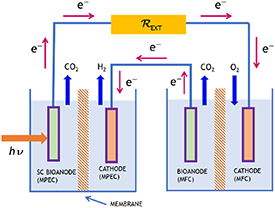
Figure 5. Microbial photoelectrolysis hydrogen-evolving cell with photobioanode, coupled to a microbial fuel cell with the possibility of electricity co-generation.
Download figure:
Standard image High-resolution imageChen et al (2013b) describe an MPEC using a nanorod n-TiO2 PCAT of 2 cm2 area in a deoxygenated 0.2 M Na2SO4 electrolyte, with electricity co-generation, operating with an external resistance between PCAT and anode. Under irradiation provided by a 300 W xenon lamp, H2 was generated at a maximum rate of 2.2 μl h−1 cm−2.
Chen et al (2017) describe an MPEC using a p-CaFe2O4 PCAT of 4 cm2 area in a deoxygenated 0.2 M Na2SO4 electrolyte, with electricity co-generation, operating with an external resistance between PCAT and anode (figure 3). Under visible light irradiation (λ > 420 nm) of intensity 100 mW cm−2 provided by a 300 W xenon lamp externally applied bias voltage, H2 was generated at a maximum rate of 6.7 μl h−1 cm−2.
He et al (2014) describe an MPEC using a n-TiO2 porous cathode of 25 cm2 area in a deoxygenated 0.1 M Na2SO4 electrolyte, operating under short circuit. The UV irradiation provided by a 30 W low-pressure mercury lamp. For an illuminated area of 15 cm2, H2 was generated at an average rate of 3.5 μl h−1; the reactor operated well for a time exceeding 200 h.
Liang et al (2016b) describe an MPEC using a Cu2O/NiOx PCAT of 1.8 cm2 area, operating with an external bias voltage of 0.2–0.4 V. Under visible light irradiation and 0.2 V external bias, H2 was generated at a rate of 5.09 μl h−1 cm−2.
Tahir (2019) describes an MPEC using a n-WO3 PCAT coated with a NiFe2O4 catalyst, operating with an external bias voltage supplied by a coupled MFC. Under visible light irradiation, H2 was generated at a rate of 10.7 μl h−1 cm−2 with a 0.3 V bias voltage.
Wan et al (2015) describe an MPEC with an external bias voltage provided by a coupled MFC, where the MPEC PCAT was a p-Si-NW PCAT. The same electrolyte was used in the cathodic and anodic compartment. Under white light irradiation, quantitative generation of H2 was detected.
Zang et al (2014) describe an MPEC with electricity co-generation using a p-Si-NW PCAT coated with MoS3 as H2-evolution catalyst, in a 0.1 M H2SO4+ K2SO4 (pH = 1) electrolyte, with electricity co-generation, operating with an external resistance between PCAT and anode. Under visible light irradiation, H2 was generated at an average rate of 7.5 μmol h−1 cm−2, corresponding to 183 μl h−1 cm−2 (SATP).
5.2. Photoanodes
The reaction sequence for an MPEC in the case of PCAT and dark bioanode, for the case of acetate oxidation at the dark bioanode, can be written in neutral solutions as

and

The possibilities (a) and (b), (b1) and (b2) mentioned in the previous subsection are also possible in the present case. However, no example of this type has been described in the literature.
An alternative system is described by Kim and Lee (2018a) consisting of a PEC using a TiO2 nanoarray photoanode (not photobioanode), and a Pt cathode, with an external bias voltage provided by a coupled MFC, with electricity co-generation, operating with an external resistance between PCAT and anode. In a strict sense, this cell is not an MPEC but a PEC coupled to an MFC. The particular MFC of these authors is based on the hydrogen evolution in place of the oxygen reduction reaction, so it could be also denoted as MEC. Their configuration uses a common Pt-coated cathode for both the MPEC and the MFC units, covered by an acrylic polymer layer as barrier to oxygen reduction so that the hydrogen evolution is the only cathodic reaction. Figure 6 shows the scheme of Kim et al and figure 7 a current flow diagram explaining the operational concept of this cell. No membrane was used to separate the electrolytes in either the MEC or the MFC subunit. Under simulated AM1.5 irradiation, the increase in the rate of H2 evolution was 1.35 μmol cm−2 h−1, based on the cathode area corresponding to 33 μl cm−2 h−1 (SATP). Under dark the respective rate is 4.39 μmol cm−2 h−1 (109 μl cm−2 h−1).

Figure 6. Microbial photoelectrolysis cell with photoanode coupled to a microbial fuel cell with dark cathode. Reproduced from [Kim et al 2018a]. CC BY 4.0.
Download figure:
Standard image High-resolution image
Figure 7. Microbial photoelectrolysis cell with photoanode coupled to a microbial fuel cell with dark cathode according to Kim et al (2018a). Current flow diagram.
Download figure:
Standard image High-resolution imageFor the optimization of the dark cathode in this type of cell the publications by and related to cathodes for microbial solar cells, as well as the references on H2 electrocatalysis mentioned in section 3.2.
6. Hybrid electrochemical photovoltaic-MECs for hydrogen evolution
The bias voltage needed to operate a PEC with both dark cathode and anode can be supplied by a solid state or electrochemical photovoltaic cell. In the context of the present review, only the latter option is of interest. At present, the most developed type of electrochemical photovoltaic cell is the DSSC, with respect to both fundamental research as well as research and development. The highest certified solar-to-electricity conversion efficiency is at present 13.0% (www.nrel.gov/pv/cell-efficiency.html, accessed 2/3/2021). Details about the DSSC are available in several reviews (e.g. Grätzel (2001), Hagfeldt et al (2010), Freitag and Boschloo (2017)) and in the book by Kalyanasundaram (2010). Figure 8 shows the connection between a DSSC and a hydrogen-generating DSSC, with the dye-coated oxide photoanode connected to the H2-evolving cathode and the dark DSSC cathode to the bioanode.

Figure 8. Dye-sensitized solar cell coupled to a hydrogen-evolving microbial electrolysis cell.
Download figure:
Standard image High-resolution image
Ajayi et al (2009), Ajayi et al (2010) and Chae et al (2009) studied an H2-evolving MEC coupled to a DSSC with a Ru dye (N719), a Pt-coated counter electrode, and, as charge-transport medium, an acetonitrile electrolyte containing the redox mediator I−/I3 −. The quantitative evolution of H2 was detected at the MEC cathode.
7. Challenges and outlooks of microbial hydrogen-evolving photoelectrochemical cells
As shown in this review, whenever a system contains photoelectrodes coupled to microorganism biofilms, an external bias in several cases is not needed, resulting in a decreasing of the operation costs. Usually, the maintenance of biofilm in a scaled-up reactor is not expensive (Blatter et al 2021). Nevertheless, further studies will give a better comprehension about the best material combination to employ in these systems to have high performances and low costs.
Energy demand is growing and hydrogen represents a carbon-free alternative to fossil fuels. Electrolytic water splitting remains a challenging technology as it is more expensive than fossil fuel-based hydrogen. Water splitting by photoelectrodes in photoelectrochemical cell is currently far from being commercially used and this mainly is due to uncertainties with respect to the cost of photocatalytic material with low stability.
Photoelectrochemical research focuses to the development of efficient, cheap and stable photoelectrodes with a narrow bandgap, allowing visible light as energy source. Usually, highly efficient photoelectrodes need multiple layers, which increases production cost in contrast to mono or bilayer approaches. If the production is expensive and the lifetime low, this technology will have no success in comparison to others. Therefore, the development of semiconductor photoelectrodes, which combine stability and low cost for the scale-up, is a research challenge to address so as to enable its obvious elegance for future application.
The use of biological systems in combination with solar water splitting technology creates a hybrid system with its own advantages. It reduces the overpotential for water splitting and allows the development of specific applications in the environmental field. In an MPEC, the reactor operation costs can be even lower than a usual PEC, if a carbon-made anodic electrode is employed. In scaled-up systems, exoelectrogenic microorganism acclimatization takes place using wastewater. The produced biofilm at the anode electrode can degrade the organic matter in wastewater effluents and, in the meantime, photoelectrodes at the cathode produce hydrogen. The number of studies in this direction is still low. Reactor performance becomes more complex. The various additional tasks to tackle are: finding the right bacterial strain, photoelectrode, membrane and possibly optimizing the kinetics. The photoelectrodes can be directly coupled with microbes, thereby developing a system with a photobioanode and PCAT. In this case a non-toxic and stable catalyst-material has to be employed. The use of biological systems, coupled with photoelectrodes, allows possibly higher current densities and faster biofilm formation, constitutes the next scientific challenge. More research efforts have to be devoted in order to identify a semiconductor material that is most appropriate to be coupled to exoelectrogenic microorganisms. On the biological side, it would be interesting to study systems where photosynthetic electrogenic bacteria are coupled to semiconductor photoelectrodes. Direct solar hydrogen production using microbial systems in combination with hydrogen evolution could open absolutely novel pathways in energy vector generation, with the additional possibility to produce carbonic fuels if the CO2 can be reduced in such systems and be transformed with specific photomicrobes into structured fuel vectors, coupling energy source production to the waste treatment.
8. Conclusions
In this review, we presented a new frontier to enhance the MBEC performance toward hydrogen generation by including the input of solar energy. Indeed, MPECs may employ various photoelectrode materials as PCATs or photoanodes. The MPEC can still be considered a novel technology, so that enhancements in term of efficiency and performance are still needed. Such systems are not considered at present a powerful source of energy, although many efforts in research are continuously leading to better results. The studies presented in this review demonstrated that the coupling of semiconductor PCATs or photoanodes to microbial oxidation reactions is feasible, resulting to the generation of hydrogen, with the possibility of coupling to the oxidative degradation of aqueous waste solutions. A further understanding of the electron transfer mechanisms from exoelectrogenic microorganisms to the electrode may give more indications to improve the performances. Additionally, fundamental photoelectrode studies are important. Finally, scale-up research and development is necessary in order to achieve sustainable MPECs operation in term of costs and half-life. In the future, MPECs technologies may provide important contributions in the generation of useful chemicals coupled to aqueous waste treatment, in an efficient, energy saving and low-cost way.
Acknowledgments
The work was financially supported by the Swiss Federal Office of Energy, Project SI/501847, and from HES-SO Valais, University of Applied Sciences Western Switzerland.
Data availability statement
No new data were created or analysed in this study.