

Abstract
We present our recent development of an integrated mesoscale digital twin (DT) framework for relating processing conditions, microstructures, and mechanical responses of additively manufactured (AM) metals. In particular, focusing on the laser powder bed fusion technique, we describe how individual modeling and simulation capabilities are coupled to investigate and control AM microstructural features at multiple length and time scales. We review our prior case studies that demonstrate the integrated modeling schemes, in which high-fidelity melt pool dynamics simulations provide accurate local thermal profiles and histories to subsequent AM microstructure simulations. We also report our new mechanical response modeling results for predicted AM microstructures. In addition, we illustrate how our DT framework has been validated through modeling–experiment integration, as well as how it has been practically utilized to guide and analyze AM experiments. Finally, we share our perspectives on future directions of further development of the DT framework for more efficient, accurate predictions and wider ranges of applications.
Export citation and abstract BibTeX RIS

Original content from this work may be used under the terms of the Creative Commons Attribution 4.0 license. Any further distribution of this work must maintain attribution to the author(s) and the title of the work, journal citation and DOI.
1. Introduction
Industrial revolutions are considered some of the most impactful socioeconomic events in human history as they have greatly benefited the economics of societies that adopted them early [1]. The third revolution started fairly recently in the 1980s and established a pervasive digital ecosystem that has matured at an exponential rate, and is itself seeding possibly the fourth revolution [2]. In this regard, metal additive manufacturing (AM), also known as 3D metal printing, is at the heart of this new development. AM holds promise for realizing innovative and rapid manufacturing of complex geometries with better control over site-specific mechanical properties and functionality [3–5]. This stands in contrast to traditional forming or subtractive manufacturing techniques which are more wasteful and can be constraining.
The Wohlers' report [6] noted an 80% rise in metal AM system sales from 2016 to 2017 and such growth rates appear to be continuing. However, to some degree, widespread adoption of AM still requires overcoming scientific challenges in addition to resolving technological and economic issues related to scaling up production and cost competitiveness [7]. In addition, more research and development work is still necessary to achieve qualification and certification of AM built parts [6, 7]. This applies to the most popular metal AM technology based on the laser powder bed fusion (L-PBF) process.
L-PBF is a layer-by-layer manufacturing process that consists of a laser beam scanning 2D patterns over a flat bed of microscopic (∼5–45 μm) metal powder particles and forming melt tracks, which fuse with the lower layer(s). A 3D object results from repeating this layer-wise process thousands of times. Despite this simplistic process, complaints about lack of precision and build quality abound, and the AM community is mystified by the 'variability' problem, where the same AM machine using the same powder and process parameters generates parts with varying quality. Barring any uncertainty about the repeatability and transferability of engineering design and toolpath between machines with varying optical setups, the laser melting process at the mesoscale is rife with random events, such as laser shadowing by large spatter. These events may introduce random defects that multiply layer upon layer.
The associated scientific challenge arises from the multiscale nature of the relevant, coupled physical processes and is exacerbated by ∼100 process parameters [8], such as laser power and scan speed, that need to be optimized. This has, in turn, implications for the uncertainty of printed metal microstructures. Therefore, it is widely believed that controlling microstructures is key for achieving desired properties and performance of the printed materials [7, 9–14]. For example, the mechanical properties are some of the most important determining factors among those that control the performance of AM structural builds. In the absence of egregious build defects, the mechanical properties and responses are largely dictated by internal microstructures at multiple length scales, including atomistic features (e.g. stacking faults, dislocations, etc) and mesoscopic features (e.g. grains, phases, and their boundaries and texture, etc). These multiscale microstructural features are highly sensitive to their processing conditions and history. Being able to harness these features for site-specific mechanical behavior control of printed metal components adds even more challenges to qualifying AM parts.
It has been widely recognized that a cost-effective approach to help solve the scientific challenge is a digital twin (DT), i.e. a digital replica [15–20] of the AM 3D printer. One general benefit of DT is its ability to streamline the procedure for understanding and optimizing the L-PBF process by reducing the number of trial-and-error tests. DT is a combination of methods, including statistical approaches (e.g. big data analytics) or numerical simulations (e.g. physics-based computational models), which bridge different physical length and time scales. Furthermore, DT simulations are becoming more affordable thanks to advances in powerful computational resources. However, there is currently no single DT that can manage all the facets of the AM challenge. Rather, several key modeling components have been developed and assembled into simulation frameworks. DebRoy et al [9, 10, 12] first laid out the building blocks of a DT. The mechanistic models block captures the main physical process from applying heat and melting to forming solidification microstructure, and it is bi-directional in that it receives process input and performs process prediction output to guide the 3D printer. A second block deals with sensing and control to check compliance with a defect-free design. A statistical model block corrects for the uncertainties in modeling by taking advantage of a data store. Yan et al [21] presented a modeling scheme to link process–structure–property–performance. The model consists of multi-scale components. At the micro-scale, the model captures powder spreading physics, high-fidelity modeling of single tracks, and microstructure development. The micro-scale model feeds into an efficient, simplified macro-scale finite element analysis code to resolve the fabrication of a full part. A data-driven mechanical component based on a reduced order model, the so-called self-consistent clustering analysis, is used along with a crystal plasticity constitutive law for material design. Herriott et al [22] presented an integrated framework that couples process, microstructure and macro-scale properties and outputs site-specific property maps. Lastly, Liu et al [23] presented a DT-enabled collaborative system that focuses on bringing together various 'Edge DTs' and data collection and management which will feed into deep learning-enabled analysis.
In this article, we present our version of a DT that specializes in the melt pool scale L-PBF process to explore AM processing–microstructure–property relationships with the goal of optimizing microstructural impacts on materials performance. As an effective vehicle for demonstrating these relationships, we exploit the fact that different laser intensity beam shapes drive distinctly different thermal processes thus allowing for distinct microstructures. We elaborate on how individual physics components are integrated in order to replicate the multiscale physics driving the interdependence of meso-nanosecond dynamical processes. Specifically, we focus on key microstructure-level phenomena such as laser–melt pool interactions, liquid–solid interface dynamics and chemistry, solidification microstructure evolution, solid-state phase transformations, and the resulting mechanical responses of metals produced by single track scans, which we find correlates with 3D parts [24–28].
2. Integrated modeling approaches for AM metal microstructures
L-PBF is a highly transient and spatially non-uniform process that couples multiple physical phenomena, including violent fluid flow in the melt pool, evaporation, rapid solidification, and solid-state phase transformation, through highly variable thermal cycling. Our DT framework has been designed as a multiscale computational framework that especially accounts for microstructure-level phenomena during AM processes (see figure 1 for key concepts and integration scheme). In particular, our approach efficiently and effectively integrates two or more of the well-established modeling capabilities that allow simulations of individual physical processes, including (a) powder-scale melt pool dynamics; (b) grain-scale solidification and solid-state phase transformation; and (c) mesoscopic mechanical responses. For the melt pool dynamics, we employ a high-fidelity model, implemented using the ALE3D (Arbitrary Lagrangian–Eulerian 3D) code (see [24, 25] for details of the model), that simulates laser–powder and laser–melt pool interactions. This serves as a main workhorse of our DT by providing high-quality thermal profiles to other physics models at finer length scales within the framework. For solidification and solid-state phase transformation processes, we rely on the highly efficient cellular automata (CA) method and/or the physics-based phase-field (PF) method, which are parameterized by well-established material models parameters and/or thermodynamic/kinetic databases (e.g. CALPHAD (CALculation of PHAse Diagram) database). For the mechanical responses, we adopt the microelasticity model and the crystal-mechanics-based constitutive model, for which the resulting microstructures simulated by CA or PF methods are used as inputs.
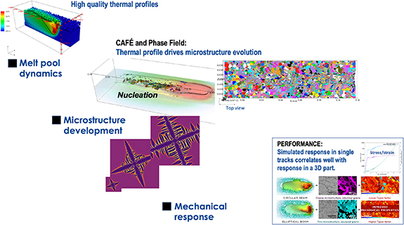
Figure 1. DT integration scheme: a high-quality thermal profile is produced using a simulation model that resolves the powder layer and accounts for laser ray tracing and melt pool dynamics. The thermal profile feeds into the CAFE method to predict the grain size distribution and orientation. This information drives a plasticity model that delivers mechanical properties. This DT was applied to a laser beam shaping study and showed that the predicted mechanical performance at the single layer correlated well with the 3D built part. Reprinted from [29], Copyright (2020), with permission from Elsevier.
Download figure:
Standard image High-resolution imageThe following sections report representative case studies demonstrating our frameworks for integrating these simulation and modeling capabilities to systematically investigate AM processing–microstructure–mechanical property relationships.
2.1. Modeling of liquid–solid interface dynamics
The kinetics of solidification is governed by liquid–solid interface dynamics for a given driving force. Gandin and Rappaz [30, 31] developed an efficient CA algorithm to describe complex solidification microstructure by relating the dendrite tip velocity  to one simple physical quantity, the thermal undercooling
  . A specific
  function is required as input. Within our DT framework, we rely on two approaches to compute
  for a given material system.
2.1.1. Analytical theory approach (Lipton–Glicksman–Kurz model)
The analytical model (i.e. Lipton–Glicksman–Kurz (LGK) model) developed by Lipton et al allows determination of a unique pair of  for a given undercooling
  , where
  with
with  and
and  being liquidus temperature and radius of curvature of the dendrite tip, respectively [32]. The total undercooling
  consists of three contributions: the thermal (
 ), solutal (
 ), and curvature (
 ) undercoolings. It is worth mentioning that the undercooling associated with attachment kinetics is neglected in the model. This assumption is thus valid for small undercooling. An expression for
  is given as follows:

where  and
and  are the latent heat and the specific heat, respectively,
  is the liquidus slope (assumed to be a constant),
  is the alloy composition,
  is the equilibrium partition coefficient (solute trapping effects are ignored),
  is the Gibbs–Thomson coefficient (namely the ratio of the solid/liquid interface energy
  to the melting entropy
  ),
),  is the thermal Peclet number:
  with
with  the thermal diffusivity, and
  is the solutal Peclet number:
  with
with  the liquid diffusion coefficient. The Ivantsov function in 3D is defined as
  , in which
  is the exponential integral.
By assuming that  can be estimated from
  derived in the linear stability analysis of a planar solidification front (namely
  with
with  being the minimum wavelength of instability), Lipton et al derived an expression for the tip radius

For a given  , equations (1) and (2) can be numerically solved using e.g. the Newton–Raphson method to find a unique pair of
  .
.
2.1.2. Numerical approach (phase-field model)
The LGK model outlined above loses validity at large undercoolings and thus may be inaccurate under some AM conditions. PF simulations provide an alternative that imposes fewer approximations and restrictions on the solidification process, permitting more accurate predictions of  versus
  for CA simulations at greater computational cost than the LGK model. Figure 2 shows a comparison of PF and LGK results for Ti–50Nb (in at. %) [33]. The agreement is very good for
  , where
  is the solidus temperature, but the LGK model significantly overpredicts
  relative to the PF results at larger undercoolings. Such differences may propagate into CA-predicted microstructures, and in such cases PF predictions will typically be more justifiable on physical grounds.

Figure 2. Growth kinetics of a dendrite tip in Ti–50Nb, as calculated using the LGK model (solid line) and a PF model (points) [33].
Download figure:
Standard image High-resolution imageThe PF simulations used to produce the data in figure 2 were implemented within the adaptive mesh phase evolution (AMPE) code. Details of the implemented model can be found in prior publications [34, 35]. In general, this model permits simulating solidification microstructure under wide ranges of cooling rates and thermal gradients, which are able to cover casting and AM conditions. It is important to note here that the model is parameterized to account for phase-, temperature-, and composition-dependent Gibbs free energies and atomic mobilities based on information from the CALPHAD framework. This PF–CALPHAD integration is key for quantitatively simulating thermally or chemically driven-microstructure evolution. The AMPE code implementing this integration has been successfully demonstrated for rapid solidification of Cu–Ni [36] and Ti–Nb [37] alloys.
2.2. Modeling of solidification microstructures
2.2.1. Cellular automata (CA) modeling informed by thermal modeling
The grain topology, size, and crystallographic texture of AM metal are determined by local melting and solidification behavior during a laser scan. Accordingly, it is critically important for the CA model to be informed by accurate prediction of local temperature evolution during the laser scan [24–27]. The AM solidification proceeds via two key mechanisms: (a) epitaxial growth from partially melted pre-existing grains in the substrate; and (b) nucleation and growth of new grains in the solidifying melt pool. Both mechanisms are well described within the CA modeling formalism. Details of the associated algorithms to account for fundamental processes leading to solidification microstructures can be found in supplementary material S1 (available online at stacks.iop.org/JPMATER/4/034012/mmedia).
The CA method requires two major inputs: (a) the time-dependent spatial thermal profile; and (b) dendrite tip velocity as a function of undercooling. Within our DT framework, the thermal profile evolution is simulated by the high-fidelity hydrodynamics model for melt pool dynamics implemented within the ALE3D code. In particular, our model accounts for effects of laser beam shapes (e.g. circular Gaussian (CG) beam, transverse elliptical (TE) beam, longitudinal elliptical beam, etc [26, 29, 38]) for L-PBF AM. The simulated profile on the coarse finite element (FE) mesh is projected onto the finer CA mesh employing an interpolation scheme based on the 'scatteredInterpolant' function in MATLAB. The dendrite tip velocity can be computed from either the analytical model (LGK model) or quantitative PF simulations as detailed in section 2.1. We present two examples based on these different models for calculating the dendrite tip velocity.
For the first example, we used a power law function fit to the LGK model results, which were informed by the materials parameters for 316L stainless steel [39]. A CA grid based on a regular lattice of cubic cells is defined and superimposed onto the irregular FE mesh. In this work, we take examples for two beam shapes, CG and TE. The sizes of the CA grids are  for the CG beam and
  for the TE beam with a grid size of
  , which correspond to total volumes of
  and
and  , respectively. The cell size of
  is small enough to resolve the branching of dendrite arms and grain competition [30]. The initial substrate grain structure is fed to the CA model using DREAM.3D [40] informed from an experimental characterization of the microstructure. Grain size distribution and crystallographic texture information were experimentally collected by electron backscatter diffraction and used as an input for DREAM.3D to generate a statistically equivalent synthetic grain structure in the substrate. The laser power and scanning speed were chosen to be
  W and
W and  mm s−1, respectively. For the nucleation model, we employed the maximum nucleation density
  and mean (or critical) undercooling
  . Figure 9 (left, top) shows an example of simulated AM microstructures for 316L stainless steel melted using the TE beam. These digital microstructures for the two beam shapes served as input microstructures for the mechanical response modeling discussed in section 2.4.
Our second example utilizes the simulated liquid–solid interface dynamics in Ti–50Nb computed by PF simulations (see figure 2) for parameterizing the dendrite tip velocity for a given undercooling. As a demonstration, we employed two scanning speeds: 500 and 200 mm s−1 for the given laser power 60 W and the CG beam shape. Single-track CA simulations for Ti–50Nb in  grids (with the cell size of
  ) are shown in figure 3. For both processing conditions, grains tend to grow epitaxially, resulting in columnar grains. However, our simulations indicate that grain texture is affected by the laser scanning speed.
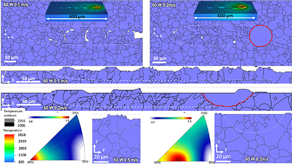
Figure 3. Microstructure for Ti–50Nb single tracks: The CA model for grain growth is parametrized using PF modeling of tip velocity as a function of thermal undercooling. Two different laser scan speeds show different microstructure growth direction as evidenced by the inverse pole figures. For both cases though, the growth is epitaxial giving columnar grains, consistent with experimental results [33].
Download figure:
Standard image High-resolution image2.2.2. Phase-field modeling informed by thermal modeling
To capture more detailed microstructural features during solidification, we also combined thermal modeling (ALE3D melt pool model) and PF modeling (by the AMPE code). Here we demonstrate two such examples for Ti alloy solidification. As the first example, a larger-scale multiphysics/thermally-informed PF modeling scheme was applied to simulating Ti–50Nb AM solidification microstructure formation as shown in figure 4 [33]. The same model parameters for the Ti–Nb system as introduced in section 2.1 were used for these simulations. Specifically, PF simulations of directional solidification were used to construct comprehensive maps of steady state solidification mode, cell/dendrite spacing, and microsegregation in  space (figure 4(a)). ALE3D simulations of single-track laser scans on bare Ti–50Nb plates were also conducted to predict thermal gradients along the melt pool solidification front (figure 4(b)). By assuming that the corresponding experiments involve similar thermal gradients (∼
 K m−1), PF predictions of steady-state directional growth characteristics could be compared with single-track experiments, and the simulations were found to provide fair-to-good predictive accuracy in most respects. Figure 4(a) also shows the corresponding solidification mode boundaries predicted by the Kurz–Giovanola–Trivedi (KGT) theory of directional dendrite/cell growth [41]. Agreement between analytical KGT predictions, PF simulations, and experimental results is good.
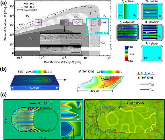
Figure 4. Multiphysics/thermally-informed PF modeling of AM microstructure formation in Ti–50 at% Nb [33]: (a) steady state solidification mode  map computed via KGT theory [41] (dashed lines) and PF simulations (colored and hatched regions) and compared with experimental results (purple-lined boxes).
  and
and  are the constitutional supercooling and absolute stability velocities, respectively. Longitudinal and transverse SEM cross sections of an experimental track are shown in the inset (scale bar: 10 μm), and examples of the different solidification modes are shown on the right. (b) Multiphysics simulations of single-track laser scans on bare plates using ALE3D. Simulation setup and surface temperature (left), and a longitudinal cross-sectional map of
  through a track centerline (right). (c) PF simulations of single-track laser scans with thermal gradients informed by the multiphysics simulations in (b). The left image is a monocrystal at low
  and the right image is a polycrystal at high
  .
.
Download figure:
Standard image High-resolution imageFor more direct microstructure-level simulations of laser scans, the thermal profiles computed with ALE3D were also used as inputs for 2D PF simulations of full tracks with time-dependent thermal/laser driving (figure 4(c)). These simulations describe microstructure formation across >100 μm track lengths with sub-10 nm resolution (the scale of the liquid–solid interface). Single crystal and polycrystal materials were studied to isolate and characterize effects (e.g. from crystalline anisotropy and competitive grain growth). Coupled PF and multiphysics approaches of this type could soon become reliable predictive tools for tailoring microstructure in the context of both AM process design and AM alloy design strategies [33].
We also considered Ti64 (Ti–6Al–4V in wt.%) as the second example, utilizing a similar integrated modeling approach. Rapid solidification microstructures of Ti64 were simulated by the AMPE code informed by a Ti64 CALPHAD database for temperature- and composition-dependent thermodynamic free energies and atomic diffusion mobilities. Like the case for Ti–Nb, the thermal boundary condition imposing the thermal gradient was informed by ALE3D melt pool dynamics simulations. More specifically, Ti64 melt pool dynamics simulations were performed for the following laser parameters: power 200 W, scan speed 1.3 m s−1, beam size (D4σ) 57 µm. The predicted temperature profiles are shown in figure 5, from which time-dependent boundary conditions were extracted for AMPE simulations.
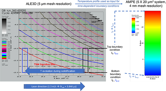
Figure 5. (Left) Temperature profile resulting from ALE3D simulations for Ti64 and (right) its use as an input for AMPE PF simulations (time-dependent boundary conditions).
Download figure:
Standard image High-resolution imageTo quantify the underlying thermodynamic forces driving phase stability and transformation within the AMPE code, we developed a comprehensive CALPHAD thermodynamic database including all phases for the Ti–Al–V system based on assessment of the relevant binary databases available in the literature: Al–Ti [42]; Al–V [43]; and Ti–V [44]. The developed database well reproduces the literature-reported property diagram (figure 6(a)) and isopleth section (figure 6(b)), demonstrating the accuracy of the phase-dependent thermodynamic inputs for simulating solidification (liquid to BCC) microstructures in the AMPE code. In addition, a database for composition-, temperature-, and phase-dependent atomic diffusion mobility was developed for the Ti–Al–V system and implemented within the AMPE framework. In particular, the BCC atomic mobilities were taken from [45–49].

Figure 6. (a) Calculated Ti64 property diagram (equilibrium phase fractions versus temperature), and (b) isopleth section (evolution of equilibrium phases in Ti94−xAl6Vx, in wt.%, versus temperature) using CALPHAD thermodynamic database. (c) Self- and impurity diffusion coefficients using our mobility database based on the equation of [50]. The x-axis represents a temperature evolution from 4000 K to 2000 K.
Download figure:
Standard image High-resolution imageDue to the lack of information, a constant diffusivity (e.g. 10−9 m2 s−1) is usually assumed in the liquid phase for all the elements within the conventional approach. However, as pointed out by Liu et al [50], the determination of diffusion coefficients of elements in liquid metals is of vital importance when investigating metallurgical processes involving molten metals. Thus, Liu et al [50] developed a predictive diffusion coefficient equation, aimed at describing the diffusivity of solute atoms in liquid metals in the case where experimental data are scarce. We adopted this approach to compute the self- and impurity diffusion coefficients in the liquid phase as reported in figure 6(c).
The integrated AMPE code allows us to run quantitative PF simulations of rapid solidification of Ti64 under relevant AM processing conditions. Figure 7 shows an example of the simulated solidification front of three separate grains, exhibiting planar (no interface instabilities, see figure 7(a)) and partition-less (no segregation of elements, see figure 7(b)) solid–liquid interfaces. In addition, as shown in figure 7(c), the interface migration rate increases with time, from the initial bottom ( = 0 m s−1) towards the top of the melt pool (
 = 1.4 m s−1 ≈ Vbeam). The characterized maximum rate slightly exceeds the laser scan speed. No grain selection, coarsening, or merging has been observed in the simulations. No nucleation of equiaxed grains is expected because of the very small constitutional undercooling in front of the solid/liquid interface and the high thermal gradient in the liquid phase. Overall, our simulation indirectly indicates that the underlying substrate microstructure should directly impact the primary β grain size as a result of epitaxial growth from pre-exiting substrate grains. In fact, our simulation results are in agreement with the widely accepted solidification theory for Ti64. Indeed, the partition coefficients of Al and V in Ti are very close to unity, meaning that almost no solute is rejected from the solid phase during solidification. In addition, the freezing range (i.e. the temperature difference between the liquidus and solidus curves) of Ti64 is extremely small (less than 1 K in our model). These factors altogether lead to a very small constitutional undercooling in front of the solid/liquid interface, thus preventing the development of interfacial instabilities such as cellular or dendritic structures. Moreover, the high thermal gradient in the liquid phase (GL ∼ 2 × 10⁷ K m−1 at the beginning of the simulation) prevents nucleation of new grains in the liquid phase. Therefore, these thermal conditions favor the development of large continuous epitaxial β grains exhibiting a planar interface without significant partitioning, as observed in our simulations.
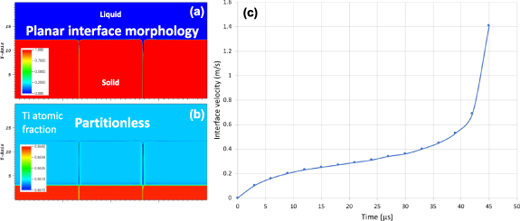
Figure 7. AMPE microstructure simulation results (40 × 20 µm2 simulation domain) after 36 µs: (a) evolution of the phase, and (b) titanium concentration in atomic fraction as function of time (time dependent temperature boundary conditions from ALE3D). (c) Solid–liquid interface velocity as function of time.
Download figure:
Standard image High-resolution image2.3. Modeling of solid-state phase transformations
2.3.1. Phase-field modeling informed by thermal modeling
Due to the unique thermal history and non-trivial elemental redistribution during the L-PBF AM process, non-conventional solid-state phase transformation microstructures may develop in metallic systems. For instance, during L-PBF AM of Ti64, the local temperature in the printed layer often cyclically varies across the  transus (i.e. the
  -to-
-to- transformation temperature) due to the thermal impact of successive layer melting. This strongly non-linear dynamic temperature profile leads to complex microstructures incorporating hierarchical and multiscale features ranging from nm to μm. Specifically, the primary
  solidification microstructure (e.g. grain size, morphology, and crystallographic texture) together with the
  second-phase precipitate characteristics (e.g. volume fraction, size, shape, orientation, coherency state, and spatial distribution) dictate the mechanical properties (e.g. strength, ductility, fatigue, and fracture toughness) of the alloy. Therefore, it is important to isolate the quantitative relationship between the temperature history and key multiscale microstructural features in order to relate processing parameters and resultant AM microstructures [14]. To this end, within our DT framework, we have formulated PF models for non-isothermal solid-state phase transformations in metallic alloys involving multiple solid-state allotropic phases for the AM processes. For Ti64 for example, the framework is based on a well-trained PF formalism for the precipitation of
  phase, coupled with reliable CALPHAD database that provides temperature- and composition-sensitive thermodynamic and diffusion mobility parameters. The cooling and heating rates are informed by the location-dependent time-temperature profile from macro-scale process models for the given processing conditions. To account for physically relevant phase nucleation events, our PF framework incorporates the explicit nucleation algorithm (ENA) based on a probabilistic Poisson seeding process [51]. For the ENA, the nucleation rate for the given temperature and local composition is calculated by the classic nucleation theory, for which thermodynamic driving force, activation energy barrier for nucleation, and kinetics factors (e.g. Zeldovich factor and the rate at which atoms or molecules are attached to the critical nucleus) are informed by both well-assessed thermodynamic and kinetics databases. Therefore, concurrent nucleation, growth, coarsening, and dissolution of different precipitate phase during rapid cyclic heat treatment, with full-field microstructural information, can be treated cohesively in a single framework within the PF context. More details can be found in our previous work [27]. Figure 8 includes an example wherein the size scale, number density, and spatial distribution of
  precipitates in a bicrystal
  matrix vary significantly with the cooling rate from
  transus temperature [27].

Figure 8. The  precipitate microstructure evolution in a bicrystal
  matrix upon cooling from a temperature (
 ) above
  transus temperature to 700 °C: microstructures at different intermediate temperatures are shown for two selected cooling rates: (a)
  and (b)
  . See the color scheme for all 12
  variants. The grain boundary plane is indicated by the transparent yellow plane. Reprinted by permission from Springer Nature Customer Service Centre GmbH: [Nature] [JOM Journal of the Minerals, Metals and Materials Society] [27] (2019).
Download figure:
Standard image High-resolution image2.4. Modeling of mechanical responses of AM microstructures
Within our DT framework, we have established a modeling scheme for assessing the mechanical responses of simulated AM microstructures. Although it is widely known that microstructural feature size and topology strongly influence mechanical properties, it is not obvious how to answer a simple question: What physical properties and microstructural parameters are the best determinants of whether a given AM microstructure is desirable or not? This is partly because AM microstructures usually exhibit strongly inhomogeneous and/or site-specific features, leading to non-uniform and anisotropic mechanical responses. In addition, the desired microstructures and properties depend on the intended applications. For instance, anisotropic and highly textured grain structures may be beneficial for improving creep resistance, whereas isotropic grain structures tend to be desirable for prohibiting crack formation and propagation, as well as improving fatigue life. Therefore, instead of focusing on a specific mechanical aspect characterized by a single value (e.g. strength) for a printed structural component, we evaluate various mechanical response characteristics of local AM microstructures and identify how those characteristics vary with microstructural features. To systematically analyze the mechanical responses of complex AM metal microstructures, three modeling elements are required: (a) reliable microstructure inputs (e.g. a digital representation of an AM polycrystal); (b) reliable materials property inputs (e.g. elastic modulus of a reference single crystal or grain); (c) validated simulation and modeling methods that can capture microstructural impacts on mechanical responses.
Accordingly, we have integrated relevant modeling capabilities for examining how the digitally represented AM microstructures mechanically respond to applied loads. Some details have been reported in our previous work on Ti64 [27]. In the present work, we employ CA generated AM 316L stainless steel microstructures informed by melt pool dynamics modeling (section 2.2). In particular, as a demonstration, we chose two microstructures produced by single melt tracks with two different beam shapes: CG and TE beams. These microstructures have been reported to exhibit meaningfully different features in terms of grain morphology (ratio of equiaxed grains to columnar/epitaxial grains) and texture in both experiments [38] and simulations [26]. Note that the employed single-track microstructure incorporates both regions that are or are not scanned by the laser as shown in figure 9. Therefore, it is important to isolate the microstructural region that is affected by the energy input (i.e. the laser in the case of L-PBF) during the AM process for fair evaluation. We first sampled regions that include reasonable fractions of the scanned portion (i.e. laser-affected zone (LAZ)) for the two cases of laser beam shapes (see figure 9 for example). During this procedure, the sampled regions were selected so that the starting substrate microstructures are identical for each of the different beam shapes for fair comparison.
For the sampled microstructures, we then evaluated several mechanical response metrics (see figure 9 for key concepts and modeling scheme). In particular, we focused on: (a) microstructure-aware effective elastic modulus; (b) spatial distribution and statistics of local stress at the microstructure-level; and (c) beyond-linear elastic regime behavior, including stress/strain curve and dislocation density evolution.
2.4.1. Effective elastic modulus calculations
We employed microelasticity theory [52] to compute the effective elastic moduli [27, 53] of digital representations of sampled AM microstructures in  grids (with the cell size of 2 μm). The mechanical equilibrium equation was numerically solved for AM microstructures under applied strains. We used the Fourier-spectral iterative-perturbation method [54, 55] to efficiently solve the equation with the position-dependent elastic moduli [27].
The computed effective elastic moduli provide useful information for analyzing overall elastic responses of AM 316L stainless steel microstructures. In fact, the computed effective moduli of the microstructures are given as full  tensors, symmetry of which slightly deviates from cubic (i.e. orthotropic symmetry is expressed) even though the input reference modulus for a single crystal incorporates cubic symmetry. Therefore, it is not obvious to define a physical quantity that comprehensively characterizes the properties of the computed effective elastic modulus tensor. It should be noted that for the sake of simple comparison between different AM microstructures in this study, we project the computed effective modulus tensor into the hypothetical cubic symmetry by defining the characteristic modulus components
  (=
(=  ),
),  (=
(=  ), and
  (=
(=  ). These indicate the average values of similar types of components in the modulus tensor. In addition, to quantify the deviation from cubic symmetry of the computed effective modulus tensor, we introduce a new metric, the so-called 'orthotropicity' factor
  =
= ![$\sqrt {{{\left[ {\Delta \left( {{C_{11}}} \right)/{{\bar C}_{11}}} \right]}^2} + {{\left[ {\Delta \left( {{C_{12}}} \right)/{{\bar C}_{12}}} \right]}^2} + {{\left[ {\Delta \left( {{C_{44}}} \right)/{{\bar C}_{44}}} \right]}^2}} $](https://content.cld.iop.org/journals/2515-7639/4/3/034012/2/jpmaterabeef8ieqn89.gif) , where
, where  represents a standard deviation of tensor components that are used for computing
  (e.g.
(e.g.  = 0: perfect cubic symmetry;
  > 0: orthotropic symmetry). Table 1 includes computed characteristic effective modulus components (
 ,
,  ,
,  ) and the orthotropicity factor (
 ) for the substrate and AM microstructures for the two selected beam shapes in comparison with the input reference values for a single crystal [56]. All of the fundamental elastic modulus parameters can be derived from
  ,
,  , and
, and  , including the Zener anisotropy factor (
 ), Young's modulus (E), bulk modulus (K), shear modulus (μ), and Poisson's ratio (ν). We caution that these parameters may not fully represent all the features of the computed
  due to our intended definition of
  ,
,  , and
, and  . However, we claim that these may well capture difference in elastic responses of complex AM microstructures with different features.
Table 1. Computed effective elastic properties of 316L stainless steel microstructures produced by single-track scans.
| Property | Before scan (substrate) | After scan (CG beam) | After scan (TE beam) | Reference value |
|---|---|---|---|---|
 (GPa) (GPa) | 281.47 | 282.31 | 277.24 | 247.50 |
 (GPa) (GPa) | 123.32 | 122.85 | 122.21 | 140.30 |
 (GPa) (GPa) | 97.00 | 96.23 | 97.12 | 123.74 |
| Az | 1.227 | 1.207 (LAZ: 1.185) | 1.253 (LAZ: 1.295) | 2.309 |
| Oh | 0.039 | 0.020 | 0.050 | 0.00 |
| E (GPa) | 230.31 | 229.88 | 228.69 | 243.02 |
| K (GPa) | 176.03 | 176.01 | 173.89 | 176.03 |
| μ (GPa) | 89.83 | 89.63 | 89.27 | 95.68 |
| ν | 0.282 | 0.282 | 0.281 | 0.270 |
As expected, the effective parameters deviate from the single crystal counterpart. However, no noticeable differences in the parameters were observed in the initial polycrystalline substrate or after scanning with both CG beam and TE beam, except for the Zener anisotropy and the orthotropicity factors. We note that the effective properties include both contributions from LAZ and non-LAZ regions in the simulated AM microstructures. In particular, for the Zener factor, we extracted the effective AZ only for the LAZ ( ) according to the formula:
 ![$A_{\text{Z}}^{{\text{LAZ}}} = \left[ {A_{\text{Z}}^{{\text{tot}}} - A_{\text{Z}}^{{\text{sub}}}\left( {1 - {f_{{\text{LAZ}}}}} \right)} \right]/{f_{{\text{LAZ}}}}$](https://content.cld.iop.org/journals/2515-7639/4/3/034012/2/jpmaterabeef8ieqn107.gif) , where
, where  is the effective anisotropy factor for the total volume of the extracted microstructure sample,
  is the anisotropy factor for the substrate before the laser scan, and
  is the volume fraction of LAZ, assuming that the anisotropy factor for the total volume is determined by a volume-averaged value. These calculations indicate that the microstructure for the TE beam exhibits stronger elastic anisotropy than the CG beam counterpart. In addition, the computed
  values indicate that the TE beam makes the microstructure have stronger orthotropic symmetry than the substrate before the laser scan, whereas the CG beam leads to more cubic-like symmetry. These arise from the microstructural differences for the two beam cases in terms of grain morphology and texture as analyzed above.
We note that full  tensors of the effective moduli can serve as input parameters for the larger part-scale thermomechanical analysis during metal AM [57]. As we discussed, the effective property parameters of polycrystalline AM or substrate microstructures are noticeably different from the parameters for a single crystal. In particular, by employing the established AM processing–microstructure relationship (sections 2.2 and 2.3), the local elastic property in the part-scale model can be continuously updated by the microstructure-aware effective moduli over the course of the part-scale AM processing simulations, which may enable in silico and in situ monitoring of site-specific, thermally induced residual stress during the process.
2.4.2. Microstructure-level microelasticity modeling
We analyzed the spatial distributions of the local internal stress within the same sampled AM microstructures under applied loads. In particular, we computed microstructure-level von Mises stress ( ) profiles based on microelasticity theory [58, 59]. Figure 10 insets show the spatial distributions of
  in the microstructures after the laser scan by TE beam (figure 10(a)) and CG beam (figure 10(b)) as examples. It is worth noting that this micromechanical modeling naturally accounts for microscopic defects such as pores at the microstructure level, which cannot be captured in larger-scale simulations (e.g. effective medium approach in which material microstructure is homogenized). For instance, the simulated AM microstructure for the TE beam scan contains pores (e.g. the sampled microstructure in figure 9 incorporates 0.48% pores in the volume fraction) and its mechanical response reflects the presence of those defects.
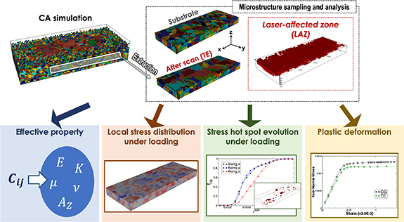
Figure 9. Modeling scheme for assessing various mechanical responses of AM metal microstructures within the DT framework: upper panel includes the procedure by which the microstructures are sampled, as well as the LAZs are identified, for further mechanical response simulations. 316L stainless steel by a single-track scan by TE beam is shown as an example. Lower panels include the mechanical responses of interest in our DT framework.
Download figure:
Standard image High-resolution image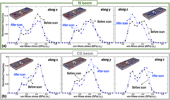
Figure 10. Statistical analysis of the simulated local internal stress in single-track AM 316L stainless steel microstructures under applied loads ( ) along three orthogonal directions (see figure 9 for definition): the spatial distributions of von Mises stress (
 ) in microstructures (insets) and corresponding statistics (plots) for the cases before and after the laser scan with (a) TE beam and (b) CG beam.
Download figure:
Standard image High-resolution imageMore quantitatively, we compared the statistics of  before and after the laser scan. To focus on the impacts of laser melting on the local stress profile, we extracted the von Mises stress (
 ) statistics only from the LAZ. For comparison, we also extracted the statistics from the same region in the substrate. By directly comparing the stress profiles from the same region (before and after the laser scan), we can explicitly isolate the impact of the AM process. We considered applied strains (
 ) along all three orthogonal directions (see figure 9 for the definition of x-, y-, and z-directions). As clearly shown in the statistics (figure 10(a)), the two microstructures (i.e. before and after the scan) exhibit different stress profiles. For all three applied strain directions, the TE beam tends to move the
  distribution toward the lower stress regime. We speculate that this is caused by the presence of relatively smaller equiaxed grains [26]. For comparison, we also conducted the same analysis for the CG beam case. Interestingly, the CG beam results in an increased population of higher
  in the microstructure (see figure 10(b)).
To utilize the stress profiles for diagnosing the mechanical failure tendency, we define so-called 'stress hot spots' with a simple criterion:  , where
  is the yield strength (=500 MPa [60] was used for this study). In fact, the stress hot spots do not necessarily point to the locations where mechanical failure occurs. However, these may indicate the probable sites with a propensity of mechanical failure due to the formation of structural defects. Figure 11(a) shows an example of stress hot spots for microstructures produced by the TE beam, which are under applied strains (
 ) along the three orthogonal directions. We observed different hot spot densities for the three different loading directions, indicating mechanical response anisotropy. We further quantified the stress hot spots. In particular, we monitored volume fractions of stress hot spots with increasing applied loads. To assess the impact of the laser scan, we first compared the hot spot evolution in the substrate microstructure and the TE beam-induced microstructure for applied strains along the three orthogonal directions (see the results in figures 11(b) and (c), respectively). Note that we only tracked the microstructure regions defined by the LAZ in both cases. Due to the innate anisotropy in system size and shape, as well as grain texture therein, the substrate microstructure exhibits directionally anisotropic hot spot evolution (see figure 11(b)). Interestingly, after the TE beam scan (see figure 11(c)), the evolution behavior along the lateral x- and y-directions (i.e. laser scanning and transverse directions, respectively) is somehow regulated and becomes isotropic, deviating from the z-directional (i.e. build direction) behavior.
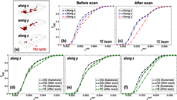
Figure 11. Identified hot spots in single-track AM 316L stainless steel microstructures: (a) an example of predicted hot spots in a microstructure produced by TE beam under applied loads along three orthogonal directions (see figure 9 for definition); (b), (c) hot spot fraction evolution with increasing applied strains along the three directions for microstructures before and after TE beam scan, respectively; (d)–(f) hot spot fraction evolution in the microstructures for CG and TE beams with increasing applied strains along x-, y-, and z-directions, respectively.
Download figure:
Standard image High-resolution imageFor more comprehensive and comparative analysis of the different beam shaping effects, we present the hot spot evolutions in the microstructures before and after the CG and TE beam scans for the individual applied strain directions. These results are shown in figures 11(d)–(f). Our results indicate that the CG beam generally modifies the microstructure in a way that the hot spot evolution becomes more sensitive (i.e. steeper slope) to the applied strain (for all three directions) as compared to the TE beam. This tendency is more apparent for strain applied along the build direction (z-direction) as shown in figure 11(f). In fact, the TE beam decreases the sensitivity of the microstructure to strain applied along the z-direction than the substrate, indicating an improved mechanical response in comparison to the CG beam.
We argue here that the evolution of hot spot density with increasing strain may indicate the mechanical response of a specific site upon mechanical loading induced by rapid local thermal cycles (i.e. thermally induced residual stress) during AM. As mentioned for the static hot spot analysis above, having the local stress exceed the yielding strength (i.e. hot spots) may not directly lead to mechanical failure. In fact, upon rapid thermal cycling, the local microstructure may experience relatively large deformation without introducing fully resolved plasticity (due to time and mechanical constraints). However, the hot spots can be considered to be regions more vulnerable to mechanical attack. Hence, we hypothesize that hot spot evolution could indicate the microstructure-aware propensity for mechanical failure under the thermal cycling conditions during the AM processes. Therefore, minimizing the hot spot density and reducing its sensitivity to increasing load would be preferred. Note that even though this modeling neglects detailed behavior beyond yielding, this computational diagnosis is simpler and more efficient for considering complex AM microstructures compared to other sophisticated mechanical models that account for detailed plastic deformation modes. We also claim that this method provides information about early-stage deformation signatures affected by microstructural features, which enables early detection of site-specific mechanical failure. For better fidelity, accurately relating this model to mechanical failure modes in a large variety of sampled AM microstructures is additionally required.
2.4.3. Plastic behavior modeling
To predict the mechanical response behavior beyond the yielding point, we also ran crystal plasticity simulations. This is far more sophisticated in its consideration of deformation modes and provides more direct information about deformation behavior beyond yielding, while more advanced numerical algorithms and extended computational resources are required. For capturing the elasto-viscoplastic response of a polycrystal, crystal-mechanics-based constitutive models are used in a standard FE formulation. The constitutive model formulation is similar to ones described in [61, 62], and the use of such models has been valuable for predicting mechanical response and for comparing these predictions to detailed experimental measurements [63–66]. Simulation throughput is facilitated by high-performance computing and the use of parallel solvers for the velocity field at each time step using the ALE3D code [67]. Figure 12 compares the computed elasto-plastic behavior of the AM 316L stainless steel microstructures for single tracks of CG and TE beams. We employed exactly the same microstructures used for the microelasticity modeling above.
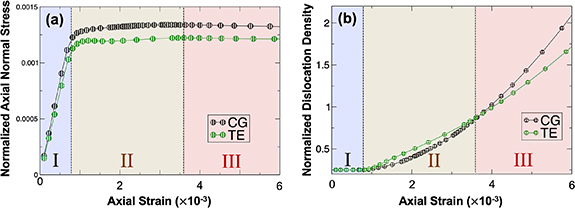
Figure 12. Simulated plastic deformation behavior for single-track AM 316L stainless steel microstructures: (a) stress–strain curves (in normalized units); and (b) normalized dislocation density evolution with increasing applied strain along the z-direction (build direction, see figure 9 for definition) for the cases of CG and TE beams.
Download figure:
Standard image High-resolution imageTwo interesting features in simulated plastic behavior are observed in figure 12 in terms of comparison between the two beam shape cases. Note that we divided the simulated elasto-plastic behavior into three regimes for comparison. First, as shown in figure 12(a) (regime I), the microstructure with the TE beam is slightly more compliant (i.e. the slope is shallower) in the elastic regime (I), which is consistent with our microelasticity modeling of effective elastic moduli (see table 1). On the other hand, the CG beam case exhibits a slightly higher yield strength than the TE beam counterpart according to the predicted stress–strain curves in figure 12(a). Second, for the CG beam case, the dislocation density initially evolves more slowly with applied strain (see the early stage in regime II), whereas it becomes more rapid at later stages (from the later stage in regime II) than the TE case. Eventually, the microstructure produced by the CG beam allows more deformation modes to be activated in regime III. We speculate that the microstructure for the CG beam incorporates more heterogeneity in the deformation field that may accommodate more dislocation activity. Combining the simulated hot spot evolution (figure 11) and dislocation density evolution (figure 12), we claim that the microstructure for the TE beam single-track has a lower propensity for mechanical failure under identical applied loading conditions. However, to certify the accuracy and relevance of the predictions, more rigorous comparison with experimental characterization and testing are required. Moreover, more foundational investigation to connect this elasto-plastic deformation behavior to actual failure modes at the microstructure level is required.
Additionally, it is interesting to note that, in both cases, the overall microstructural setups and the corresponding applied loading conditions are configured in a way that the dislocation density does not make much contribution to the flow strength, resulting in fairly small amount of hardening for small amounts of strain in this study. Although we demonstrated the difference in elasto-plastic responses between CG and TE beam cases in figure 12, more quantitative understanding requires the microscopic analysis of the operating deformation modes and their activities/sensitivities to the applied loading conditions and grain/cell boundaries in the microstructure, which are currently underway.
3. Interactions between digital twin and experiments
Within our integrated DT framework, the multiphysics melt pool dynamics model (implemented in the LLNL ALE3D code) and simulations generate the most critical information, including dynamic thermal profile and melt pool behavior, for other modeling techniques. Therefore, it is important to certify the validity of the melt pool dynamics model by interfacing with experimental observations and characterizations. This section reviews a few examples that demonstrate direct or indirect modeling-experiment coupling, which provide ample evidence for the validation. Furthermore, we present how the validated model can be cohesively used to help interpret experimental observations and inform build strategies, illustrating the utility of the DT framework.
3.1. In situ experiments to validate digital twin models
Validation of multiphysics simulations of melt pool dynamics requires high temporal and spatial resolution in situ experimental measurements of laser–material interactions within and surrounding the melt pool. Such validation efforts are important to confirm the accuracy of the associated hydrodynamics model because of uncertainty in the materials properties used in most simulations. For example, surface tension and viscosity as a function of temperature is not always precisely known from room temperature to the boiling point for many cases of materials of interest. A variety of experimental techniques have been used to validate the melt pool dynamics simulations. Our initial validation efforts have been focused on comparison of ex situ melt pool depth measurements with model predictions [25]. These comparisons show good agreement and verify the basic validity of the model as an important prerequisite. However, these are not sufficient to completely validate all of the dynamics observed in the simulations, as ex situ comparisons only quantify the final state of the system and do not capture the transient nature of the heat transfer process and resulting localized fluctuations in pressure and surface tension. Therefore, more sophisticated in situ experimental techniques for L-PBF have also been used for validation of the melt pool dynamics model. General application of in situ diagnostic techniques for process development and monitoring have been well reviewed in the literature [68].
Comparison of simulations and in situ absorptivity measurements show good agreement, validating the melt pool dynamics model with laser ray-tracing for simulating laser energy deposition within our DT framework. The measurements verified that the model can accurately capture variation of effective absorptivity caused by changes to vapor depression shape as a function of laser power and scan speed (see figure 13(a)) [69]. Similar experimental results for dynamic absorptivity measured by a complimentary method also show good agreement with the absorptivity behavior predicted by the melt pool dynamics simulations, providing additional evidence for the validity of the model [70, 71]. High speed optical imaging experiments capture fluid flow and material ejection (spatter) dynamics from in and around the melt pool during L-PBF and provide a key validation dataset to determine how accurately the ALE3D code simulates fluid dynamics near the surface of the melt pool. Comparisons with experiments indicate that the implemented multiphysics model accurately describes many of the important spatter generation mechanisms [72].

Figure 13. DT validation and practical use: (a) with integrated full laser ray tracing, the absorptivity, just like melt pool dimensions, is an output of DT and is validated against experiments. [69] John Wiley & Sons. [© 2019 WILEY‐VCH Verlag GmbH & Co. KGaA, Weinheim]. (b) DT reveals unexpected melt-pool and spatter dynamics at the start of the track, given an unoptimized scan strategy. Very large back-spatter arises. These were shown to persist in a self-replicating mechanism in [28] and can generate further defects. A stability criterion implemented using feedback control delivers a power map scan strategy that prevents back-spatter, as well as start of track pores and frozen end of track depression. These two defects arise due to uncontolled and unstable melt pool. From [28]. Reprinted with permission from AAAS. (c) The same stability criterion can be applied to prevent keyhole pores induced during a turn-around. From [28]. Reprinted with permission from AAAS.
Download figure:
Standard image High-resolution imageFurther validation of subsurface behavior predicted by ALE3D melt pool dynamics simulations requires comparison with x-ray imaging data, which is the only experimental method that can directly quantify subsurface fluid flow during laser-induced melting of metals on the short timescales relevant to AM [73–75]. Direct comparison between the simulations with laser ray-tracing physics and high-speed x-ray imaging illustrates that in both instances, surface ripples travel upwards and downwards on the front of the vapor depression wall, and correlate with ripples and instabilities on the rear surface of the vapor depression [76]. Similar rippling effects have been observed experimentally in the literature and correlated to spatter behavior [77], demonstrating that the implemented multiphysics model in the ALE3D code accurately captures physical phenomena that lead to both keyhole-type porosity and spatter, which can later lead to lack of fusion porosity during L-PBF.
Our melt pool dynamics predictions in L-PBF indicate the central role of Marangoni convection to determine the shape and flow dynamic behavior of the melting zone [25]. X-ray imaging experiments using tracer particles to directly measure flow dynamics in the melt pool broadly agree with the prediction that Marangoni convection is the central mechanism at play in melt pool flow [78], even though quantitative comparisons between these two published data sets are not feasible because they analyze different materials. Finally, spatter behavior and corresponding defect generation predicted by our melt pool dynamics simulations agree well with experimental measurements from x-ray imaging (see figure 13(b)). Specifically, our model accurately predicts large spatter droplets ejected backwards at the start of a laser strike, known as start of track ejections [28]. The resulting spatter lands at a neighboring site on the build plate. X-ray imaging experiments with simulated spatter particles illustrate that when the laser scans over these large spatter particles resting on the powder bed, the melt pool depth decreases and can lead to lack of fusion porosity. These experimental observations are reproduced in simulations of similar cases where a large spatter particle is resting on an otherwise normal powder bed [28]. Note that this fundamental understanding enables us to identify scan strategies to prevent formation of defects (see figures 13(b) and (c)).
These examples of experimental validation via absorptivity, visible light imaging, and x-ray methods certify that the multiphysics modeling factors are well integrated in a physically consistent way within the ALE3D code framework, as well as assumptions for the temperature-dependent material properties do not substantially degrade the accuracy of predictions by the melt pool dynamics simulations.
3.2. Roles of digital twin in guiding and analyzing experiments
One important aspect of a DT is its ability to complement and guide experimental trials. Systematically designed simulations under controlled conditions have provided key information for better analyzing the experimental observations and guiding AM processing conditions.
Examples include our recent effort for helping explain the origin of a qualitative and quantitative difference in microstructures in L-PBF 316L stainless steel produced by different laser beam shapes (i.e. CG beam vs. elliptical beam) under otherwise identical processing conditions [29]. The most important implications of the microstructural difference are projected to substantial variation in mechanical behavior analyzed above (see section 2.4) and the Taylor factor analysis in [29]. The assessment favoring the elliptical beam was based on overall refinement of grains, ∼50% increase in number of equiaxed grains, and reduction in texture. This was of course an important finding as most metal AM techniques are based on the traditional Gaussian laser beam and by default mostly result in columnar grains [29, 38].
Despite its significant impacts, experimental investigation and development of shaped beam printing strategies is time consuming and requires overcoming several technological challenges. This usually involves three important steps. First, single track trial experiments are necessary to isolate key distinctive physical features associated with the laser–material interaction for the different beam shapes. Second, the technical challenge of manipulating a non-symmetric laser beam shape when performing complex scan maneuvers such as at corners should be resolved. Third, it should be confirmed that all the benefits of a new beam shape are not washed away by thermal cycling during the 3D build. One lesson learned through our experimental research is that, while thermal cycling affects the microstructure present in a single track through recrystallization, the favorable grains obtained at the single-track-level are not completely washed away (see figure 14(b)). This makes it reasonable then to perform single track DT studies and correlate the results to full 3D builds.

Figure 14. Understanding laser beam shape effect on microstructure: (a) different laser beam profiles can generate different solidification rates R and thermal gradient G [26, 29]. The TE beam case has more locations where G is low and R is high, i.e. G/R is low, therefore, more propensity to produce equiaxed grains than the CG beam case. The simulated trends in a single track persist in a full 3D part. Reprinted from [29], Copyright (2020), with permission from Elsevier. (b) The etched optical micrographs of cubes built using P = 250 W show large melt pool difference between a Gaussian and TE beam, which is evidence of large difference in melt pool thermal profiles. When inverse pole figure (IPF) maps are partitioned to show only equiaxed grins (i.e. areas occupied by columnar grains appear black), the cube built using an elliptical beam shows a higher density of finer, randomly oriented equiaxed grains which can lead to higher mechanical strength. The build direction is towards the top of the page for all micrographs and maps.
Download figure:
Standard image High-resolution imageIn this regard, our DT has provided key insight into microstructural mechanisms arising when applying different laser beam shapes (e.g. Gaussian and elliptical beams) to the L-PBF process. DT simulation studies have isolated the effect of the beam shapes on microstructure [26] and agreed well with the single-track experiments [38], as well as the 3D build study [29]. Since L-PBF is a thermally driven process, it is important to capture the 3D thermal profile in order to be predictive and able to explain the resulting microstructures. Our DT has modeled accurately the thermal field during the steady state, as well as the transient state. Using a parametric study of the CAFE (cellular automata finite element) model, we found that TE beams (with the major axes perpendicular to the scan direction) lead to the highest propensity for formation of equiaxed grains. While the simulation results suffer from the uncertainty arising from an un-calibrated (parameter sweep) maximum nucleation density for the CAFE nucleation algorithm, the simulations show a trend consistent with the experiments, in terms of a decrease in texture and grain size distribution, as well as increase in propensity to produce more equiaxed grains at lower scan speed (i.e. larger melt pool), when the TE beam is applied. The physical explanation of these observations has relied on a traditional G (thermal gradient) and R (solidification velocity) analysis that clearly showed the TE beam producing more locations in the melt pool with larger R and lower G values, resulting in lower G/R ratios (see figure 14(a)). Interestingly, the trends observed in the steady state do not hold throughout the length of the track. What complicates this explanation is the introduction of transient states at the start and end of the single track, where the laser power and scan speed can abruptly change. Our DT simulations of thermal profiles at these locations implied that more equiaxed grains are generated if the applied laser beam produced a deeper melt pool that takes more time to freeze, which then creates higher supercooling.
Another example includes our DT–experiment integration by which a particular defect formation mechanism during metal AM was elucidated. As a result of this integrated effort between modeling and focused experiments, our DT provided valuable insight for developing L-PBF build strategies. More specifically, Martin et al used high speed x-ray radiography to observe pore formation during laser turnaround points caused by laser deceleration near the turn [79]. To develop a mitigation strategy for this pore formation mechanism, experimental observations coupled to melt pool dynamics simulations by the ALE3D code, using a stability criterion that implements a proportional–integral–derivative control, yielded a laser power mapping strategy which maintained a constant melt pool depth throughout the turn. The strategy substantially reduced the likelihood of pore formation at the turning point, illustrating a powerful mitigation strategy for a class of L-PBF defect [79]. This example illustrates that, in addition to its roles as a powerful tool for describing laser–material interactions, DT can also be practically used to develop advanced strategies for mitigation of the formation of specific defects during L-PBF.
The last example is our recent ALE3D melt pool dynamics simulation complementing a relatively new in situ LPBF monitoring methodology based on thermionic emission. This experiment–modeling integration has verified a mechanism that spikes in the thermionic signal correlated with spatter formation [80]. The simulation of a laser turn point region also showed that the effects of surface temperature and recoil pressure on melt depression depth lagged the thermionic signal response due to the inertia of the liquid.
4. Future directions for digital twin development
Although we have reported meaningful integration schemes established within our DT framework, the current framework requires further development for more efficient and accurate predictions, as well as wider ranges of applications in terms of parameter spaces for materials, phenomena, and processing conditions. This section addresses a few examples of the 'wish-list' for further implementation by which the predictability and applicability of the DT framework can be improved.
4.1. Accelerating optimal process space discovery with surrogate models
Machine learning (ML) is expected to play an increasingly important role in improving the quality and certifiability of 3D printed parts [81–88]. By definition, ML models promise performance improvement on a task without being explicitly programmed [89]. Training data is used to fit the model's parameters and care must be taken in generalizing the model to perform fast predictions with low bias and variance. A successful ML model benefits from large amounts of data. Fortunately, AM technologies form an ecosystem rich in multi-modal data, where information is combined from various sources. Sources include in situ video melt pool data used to train a convolution neural network [90] to monitor LPBF track quality on the fly, characterization of powder feedstock micrographs (termed the 'microstructure fingerprint') used to quantify and qualify the effect of powder [91], or complex laser trajectories to minimize shrinkage [92]. These sources provide ample opportunities for ML to control and improve the process.
The application of high-fidelity modeling discussed in this paper to produce a database to help in ML optimization can be prohibitively expensive. However, the flexibility that modeling offers in changing to any new material or process setup, without the overhead in time and manpower required in experiments, remains highly desirable. We show that ML methodologies could still be applied with high-fidelity models when coupled with surrogate models. These could be physics based using fast analytical solutions [93] or statistical in nature using ML methodologies such as Gaussian processes (GP) [94].
Using the GP approach [94], we showed that it is possible to successfully develop a Gaussian surrogate model based on a fairly small training set (26 high-fidelity simulation data points) (figure 15(a)), which demonstrates the efficiency of this approach. Moreover, GP delivered error bars on the predictions, which is very important since often what is missing in numerical predictions are the uncertainty bounds. Since the training data were composed of melt pool depth predictions, the GP process predicted melt pool depth for a given laser power and scan speed combination in an LPBF process (figure 15(b)). The uncertainty (figure 15(c)) varied depending on the location of depth prediction in a power–speed phase diagram. Typically, a reasonably low error of 3 μm was customary between regions (interpolation) where power–speed training data was dense. As predictions were made away from the bounds of the training data (extrapolation), the uncertainty of course increased due to the lack of data to train the model in those regions. This illustrates the limitation of such an approach as it excels in interpolation but not in extrapolation. Nevertheless, this framework is useful when there is a need to evaluate depth or other properties derived from depth multiple times. Note that the cost of doing a prediction is negligible, indicating the usefulness of the GP approach.

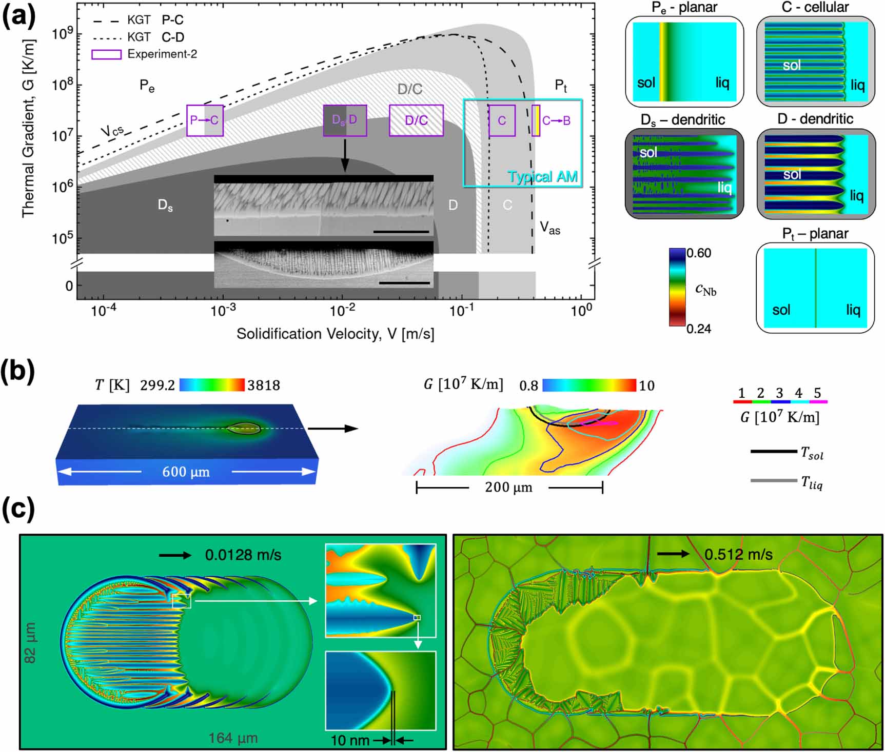
Figure 15. GP framework for optimal L-PBF process window: (a) the training data consists of high-fidelity simulation of melt pool physics. Twenty six depth data points in total were sufficient to train an accurate GP. (b) The GP response surface gives melt pool prediction for a laser power and scan speed combination, along with the error bars in (c). (d) The final process window showing a comparison between two optimal criteria derived using GP and a physics based analytical model. Reprinted by permission from Springer Nature Customer Service Centre GmbH: [Nature] [The International Journal of Advanced Manufacturing Technology] [94] (2017).
Download figure:
Standard image High-resolution image
The framework was extended to determine an optimal process window in power–speed phase space (figure 15(d)). This is described in [94] as creating a 'material data sheet standard that describes regimes where the process can be expected to be robust'. In fact, it would be beneficial to provide a 3D printing practitioner such a data sheet when handling any new AM material. The data sheet describes the expected melt depth and partitions the power–speed phase space into undesirable regions to be avoided due to prevalence of keyholes and associated pore defects, as well as regions of low melt pool depth or balling defects due to operating the laser in the low power conduction mode. The criterion used to create the process window is based on an ideal aspect ratio 1 of depth over width and is indicated by the white contour lines in the graph (figure 15(d)). As the power increases and the speed decreases, L-PBF process approaches the keyhole regime, indicated by large depth over width ratio reaching values up to 6 [69]. The GP predicted optimal process window agrees with a basic physics based analytical model described by the red curve in (figure 15(d)) and is related to the normalized enthalpy as described in detail in [94]. This GP framework approach was further extended in [95] to produce ultra-high strength austenitic steel and avoiding printing parts with defects.
4.2. Further modeling components for wider applications of a digital twin
The DT framework can benefit from highly accurate smaller scale simulations such as atomistic-level simulations [96, 97]. In conjunction with experimental characterizations, atomistic scale modeling and simulations may provide reliable information about atomic structures and energetics of structural defects (e.g. interphase boundary, pore surface, stacking faults, etc), as well as local alloy chemistry and kinetic coefficients associated with non-equilibrium solid/liquid interfaces [98–100]. This information may serve as more accurate input parameters for mesoscopic microstructure-level simulations, improving the predictive power of the microstructure-level modeling within the DT framework. In addition, the nucleation models used in solidification and solid-state phase transformation simulations [26, 27] can be further refined and improved by multiscale integration of atomistic [101, 102] and mesoscale [103–106] approaches. Uncertainty in mesoscopic nucleation models often arises from the lack of understanding of beyond-ideal nucleation behavior and the associated parameters during non-equilibrium and dynamic processes [107]. Therefore, more sophisticated and integrated theoretical effort is needed to address these challenges.
More modeling functionalities for assessing microstructure-dependent properties and behavior can be added to the framework. For example, in addition to mechanical properties, the unusual AM microstructures may substantially affect their corrosion behavior [108–110]. Since many corrosion mechanisms (e.g. pitting, hydriding-induced embrittlement, etc) are strongly influenced by local microstructural features [111], AM microstructures are expected to exhibit nontrivial difference in corrosion kinetics and thermodynamics as compared to metal microstructures produced by conventional approaches. The reliable digital representations of AM microstructures predicted by the current DT framework can serve as inputs for further corrosion modeling. In addition, the corrosion simulation capability can be incorporated within the DT as an additional property prediction tool.
More direct integration of solidification and solid-state phase transformation models should be pursued. It is worth pointing out that simulated as-solidified primary microstructures incorporating both local chemical and grain structural information are needed as inputs for the PF models of second-phase precipitation. The reasons are two-fold. First, the strong chemical segregation during solidification, resulting in inter-dendritic regions with high solute content, may lead to formation of desired or undesired phases. Examples include the formation of carbides, Laves and TCP phases in Ni-base superalloys. Second, the crystallographic texture of the secondary phase is dictated by the grain texture and grain boundary structure of the primary phase. For instance, the texture of multivariant  precipitates in a Ti alloy is determined by their well-defined Burgers orientation relationship with the primary
  phase and the associated variant selection rules near grain boundaries [112, 113]. Therefore, the crystallographic texture of the
  primary phase is directly projected to the
  phase texture.
For solid-state phase transformation models for AM, further improvement for handling rapid cooling rates is needed. The cooling rate has a strong influence on transformation pathway (i.e. the type of phases formed upon cooling). Specifically, for a Ti64 alloy, a cooling rate above  results in a fully martensitic microstructure, while this type of transformation is gradually replaced by a diffusion-controlled transformation as the cooling rate decreases. A cooling rate slower than
  leads to the formation of widmanstatten structure consisting of the equilibrium
  phase. To better understand the correlation between the spatially variable nonlinear time–temperature profile and a site-specific microstructure, the cooling rate-dependent transformation pathway needs to be incorporated in the PF model for second-phase precipitation. This could be accomplished through ENA by implementing cooling-dependent nucleation rates for both equilibrium and non-equilibrium phases.
5. Conclusions
Manufacturing innovation has been one of key factors for realizing economic breakthroughs, which has led to drastic changes in several industry sectors, as well as quantitative and qualitative changes in human life. Metal AM holds promise for revolutionizing our approach to producing key metal components in a wide spectrum of practical applications. L-PBF is by far the most common process for direct AM metal fabrication. Recent advances in multidisciplinary scientific and engineering research have brought the L-PBF technique to a critical juncture where metal components with complex geometries, which cannot be fabricated through conventional processing routes, can now be AM. However, its application space is still limited by poor qualification and certification of the manufactured components. This partly arises from the lack of understanding and control of associated microstructures and materials properties, which are highly sensitive to AM processing parameters. It remains challenging to accurately capture the dynamical evolution of the physical processes and to correlate them to processing parameters by experimental trial-and-error approaches alone. To this end, a DT has been considered a cost-effective and time-efficient approach to resolve the associated scientific and engineering challenges.
We have developed a comprehensive DT framework to account for the complicated AM processing–microstructure–property relationship. Due to the large breadth of length and time scales of operating mechanisms during AM, it is not currently feasible to develop a unified (or all-in-one type of) simulation framework to account for all the multiscale features. Instead, within our DT framework, necessary individual modeling components have been developed, subsets of which have been integrated. We demonstrated how the modeling building blocks were integrated to capture the effects of physical processes at one length/time scale on the behavior at the other scales within our framework. Specifically, our high-fidelity melt pool dynamics simulations inform the liquid–solid interface dynamics models of the thermal history and profile, by which the interface migration velocity is related to the local undercooling via either analytic theory (LGK model) or a numerical approach (PF simulations). Subsequently, the interface kinetics models are used by the CA method to simulate complex solidification microstructures during the laser scan. This integration scheme naturally connects the processing conditions to the resultant microstructures, which enables us to assess the impacts of the laser processing conditions on the produced microstructures. For example, our DT framework could capture the difference in microstructural features in terms of grain morphology, size, and texture for different laser beam shapes (e.g. Gaussian beam vs. elliptical beam). Furthermore, we elaborated how single-track performance was optimized using the laser beam shaping strategy. The findings agree with experimentally 3D printed metal parts that exhibited higher grain refinement and strength when using an elliptical laser beam instead of the conventional Gaussian (circular) beam. We also discussed the CALPHAD-informed PF approaches that capture morphology of multiple grains of AM Ti alloys during rapid solidification or solid-state phase transformation. For these cases, melt pool dynamics simulations provide high-fidelity thermal profile data, which determined the thermal boundary conditions for the PF simulations.
The mechanical properties and responses of the simulated AM microstructures are eventually assessed within our framework. To comprehensively examine the mechanical response, we numerically evaluated several metrics that represent mechanical responses to applied loads. In particular, we demonstrated how the effective elastic modulus, local microelastic response, and elasto-plastic behavior are computed for the given digital representations of AM microstructures generated by CA simulations. Based on these computations, we laid out a preliminary approach for examining the propensity of mechanical failure of complex AM microstructures by analyzing stress hot spot evolution and dislocation density evolution with increasing applied loads.
The validity and practicality of the DT framework were illustrated by some representative examples of our prior efforts toward integrating modeling and experiments. Particularly, the advanced in situ experimental techniques permitted direct comparisons between high-fidelity melt pool dynamics simulations and experiments for non-equilibrium microstructure-level processes during laser scans, including variation of effective absorptivity, dynamic spatter behavior, and defect formation. The validated model has subsequently been used to elucidate microstructure formation mechanisms, which are sensitive to AM processing conditions. For instance, our DT simulations helped to verify the origin of the beam shaping effects on resultant microstructures by relating local thermal gradient/solidification rate to the grain nucleation tendency. Finally, the integrated DT framework and the established mechanistic understanding could provide insightful guidance for scan strategies that can minimize process-induced defects such as pores.
We also discussed possible future directions for further development to improve predictive capabilities and widening the application space of the DT framework. The DT framework can benefit from available ML algorithms as more experimental and simulation data become available for training ML models. These models are expected to accelerate the discovery of optimal processing windows for AM. Smaller scale modeling approaches such as atomistic simulations may improve the accuracy of the DT model prediction by providing more reliable input parameters and/or foundational understanding of phase nucleation mechanisms. The implementation of more modeling functionalities for microstructure-dependent property predictions (e.g. corrosion), as well as more realistic modeling factors (e.g. rapid cooling rates for solid-state phase transformations), should enhance the practicality of the DT framework.
We want to emphasize that our DT framework—developed on the basis of the interactions between processing, composition, and microstructure—is generally applicable to a variety of printable metallic materials and thus will contribute to the optimization of existing alloys and exploitation of the enormous opportunities inherent in the AM technique.
Acknowledgments
This work was performed under the auspices of the U.S. Department of Energy by Lawrence Livermore National Laboratory under Contract No. DE-AC52-07NA27344. This work was funded by the Laboratory Directed Research and Development program at LLNL under the project tracking code 18-SI-003. A P, J-L F, and W K acknowledge the support from the High-Performance Computing for Manufacturing program under tracking code HPC4Mfg-42141.
Data availability statement
All data that support the findings of this study are included within the article (and any supplementary files).