

Abstract
Many strategies have been adopted to engineer bone–ligament interface, which is of great value to both the tissue regeneration and the mechanism understanding underlying interface regeneration. However, how to recapitulate the complexity and heterogeneity of the native bone–ligament interface including the structural, cellular and mechanical gradients is still challenging. In this work, a bioinspired grid-crimp micropattern fabricated by melt electrospinning writing (MEW) was proposed to mimic the native structure of bone–ligament interface. The printing strategy of crimped fiber micropattern was developed and the processing parameters were optimized, which were used to mimic the crimp structure of the collagen fibrils in ligament. The guidance effect of the crimp angle and fiber spacing on the orientation of fibroblasts was studied, and both of them showed different levels of cell alignment effect. MEW grid micropatterns with different fiber spacings were fabricated as bone region. Both the alkaline phosphatase activity and calcium mineralization results demonstrated the higher osteoinductive ability of the MEW grid structures, especially for that with smaller fiber spacing. The combined grid-crimp micropatterns were applied for the co-culture of fibroblasts and osteoblasts. The results showed that more cells were observed to migrate into the in-between interface region for the pattern with smaller fiber spacing, suggested the faster migration speed of cells. Finally, a cylindrical triphasic scaffold was successfully generated by rolling the grid-crimp micropatterns up, showing both structural and mechanical similarity to the native bone–ligament interface. In summary, the proposed strategy is reliable to fabricate grid-crimp triphasic micropatterns with controllable structural parameters to mimic the native bone-to-ligament structure, and the generated 3D scaffold shows great potential for the further bone–ligament interface tissue engineering.
Export citation and abstract BibTeX RIS
1. Introduction
The interface between bone and ligament plays an essential role in the musculoskeletal system, which serves to facilitate synchronized joint motion and allows them to bear weight [1]. As a frequently injured tissue, ligament has limited self-healing potential [2]. To date, the clinical treatment of ligament injury and the regeneration of ligament-to-bone-junction are still challenging in orthopedic medicine [3]. Meanwhile, although the healing process of bone–ligament interface has been explained and discussed by various hypotheses, it is still not fully understood [4]. Therefore, engineering in vitro bone–ligament interface structure is of great value to not only the tissue graft development for the damaged interface regeneration, but also the better understanding of the structure–function relationship and the mechanism underlying interface regeneration.
Bone–ligament interface mainly consists of three regions, composed of bone, fibrocartilage and ligament. And the interface is a typical heterotypic tissue with complex and anisotropic structure varying gradually from hard bone to soft ligament [5]. Thus, how to design and fabricate bioinspired multiphasic configuration with structural, cellular and mechanical gradients to recapitulate the complexity of the native tissue is the central challenge [6]. Various techniques have been developed to prepare multiphasic structures for the in vitro engineering of the interface [7–11]. Lin et al designed and utilized a novel electrospinning nanofiber collecting device to fabricate an integrated PCL nanofibrous scaffold with a 'random–aligned–random' structure to mimic the bone–ligament connection, which stimulated tenogenesis and osteogenesis chemically and structurally [8]. Lui et al fabricated a bone–ligament–bone triphasic scaffold by 3D printing for scapholunate interosseous ligament reconstruction [10]. Jiang et al prepared an electrospun scaffold with gradient distribution of BMP-2/nanoHA and fiber orientations for BMSC differentiation and ligament–bone osteointegration [9]. Although great progress has been made, most of the reported structures still lack the recapitulation of the complexity of the native bone–ligament interface, especially the crimp feature of the collagen fibrils in ligament.
In the ligament region, a high degree of cell alignment is present and the collagen fibrils possess parallel and regular crimp pattern, so that to provide mechanical strength for ligament fibroblasts to undergo the axial deformation during crimp unfolding [12, 13]. Considering the significance of the crimp structure of the collagen fibrils, several approaches have been proposed to fabricate crimped fibers or patterns to recapitulate the native crimped collagen fibril structure. Thereinto, a simple and most applied method is based on electrospinning [14–16]. Chao et al [14] achieved crimped poly-L-lactic acid fibers by briefly heating and ethanol treatment to the electrospun parallel fibers. Liu et al [15] also used ethanol treatment to prepare crimped poly(lactic acid) nanofibers and the degree of crimping can be roughly controlled by preseting the shrinkage ratios of the electrospun fibers before ethanol treatment. Although the plasticizer-based treatment to electrospun fibers is a simple method to obtain crimped fibers, the crimp degree, crimped length and their consistency of the fibers are still difficult to be precisely controlled.
Melt electrospinning writing (MEW) is an emerging 3D printing technology to fabricate microfiber patterns with pre-defined geometries by controlling the printing patch [17, 18]. Due to the versatility, MEW has been widely used to fabricate various structures and scaffolds for tissue engineering applications [19–22]. MEW has also been verified to fabricate crimped fibers by several groups. In the first report of MEW, Brown et al [23] presented that coiled fibers would occur once the collector speed below the electrified jet speed, which was also been exhibited by Castilho et al [21]. Bas et al [24] prepared crimped patterns by MEW as soft biomaterials and studied the mechanical properties. Hochleitner et al achieved crimped fibers by MEW below the critical translation speed (CTS), and found that the MEW crimped fibers possessed non-linear mechanical properties, which is similar to that of the native ligament or tendon tissue [13]. However, the further process optimization for the MEW crimped fibers, such as the crimp angle and length, as well as the effect of the crimp parameters on cell alignment and other behaviors were not studied yet.
Meanwhile, MEW has also been widely reported for the fabrication of the scaffolds for bone tissue engineering and offers great advantages. Eichholz et al prepared controlled fibrous architectures with different angles between fibers on adjacent layers by MEW and found that 90° fibrous architecture was optimal for the osteogenic differentiation of human skeletal stem cells [25]. Fuchs et al used MEW to prepare PCL scaffolds with different fiber spacings from 225 to 500 μm, which were demonstrated to be beneficial for osteoblast growth [26]. Our recent study also proves that MEW microfibrous structure has a certain osteogenesis promotion ability [27].
Considering the printing flexibility of MEW, and the feasibility of MEW to print crimped fibers, as well as the verified advantages of MEW grid structures for osteogenesis, a bioinspired grid-crimp micropattern was fabricated in this study by MEW for mimicking the native bone–ligament interface structure. Firstly, a MEW based crimped fiber writing method was developed and optimized. The effect of the main process parameters (air pressure and collector speed), on the morphology of the printed patterns was studied. Then crimped fiber patterns with different spacings and crimp angles were fabricated and used for cell alignment studies. MEW grid patterns with different fiber spacings were also fabricated and the effect on the osteogenic activity of Saos-2 cells was evaluated. Next, MEW grid-crimp micropatterns were printed and applied for cell co-culture and interface formation. Finally, the MEW grid-crimp micropattern was rolled up to form a scaffold, which would be potential as a graft for bone–ligament interface tissue engineering.
2. Materials and methods
2.1. Materials
PCL pellets (CapaTM 6800) were purchased from Perstorp. Phosphate buffer saline (PBS), Dulbecco's modified eagle medium (DMEM), McCoy's 5 A medium (modified), 4% paraformaldehyde solution, fetal bovine serum (FBS), penicillin/streptomycin (P/S) and trypsin were from Gibco. Bovine serum albumin, BCA protein assay kit and alizarin red sulfate (ARS) were all obtained from Guangzhou Ruishu Biotechnology Co., Ltd Alkaling phosphatase (ALP) staining kit and ALP detection kit were purchased from (Beyotime,China). Triton X-100 was from MYM biological technology company. Phalloidin-tetramethylrhodamine isothiocyanate (Phalloidin-TRITC) and 4', 6-diamidino-2-phenylindole (DAPI) were provided by Beijing Solarbio Science & Technology Co., Ltd Cell tracker CM-DIL (C68H105Cl2N3O) and CMFDA (C25H17ClO7) were purchased from Shanghai Yisheng Biotechnology Co., Ltd.
2.2. Fabrication of grid-crimp micropatterns via MEW
In this study, grid-crimp micropatterns were fabricated by MEW for bone–ligament interface study. During MEW, PCL pellets were heated to 100 °C and pressed out from a grounded nozzel tip (15 gauge) under certain air pressure. An ITO conductive glass as a collecter was placed on a X–Y movable stage connected to a negative voltage of 1.55 kV, and the distance from needle tip was set to be 1 mm. Under the electrostatic force between the nozzle and the collector, as well as the movement of the platform controlled by G-code, PCL melt jet can be collceted on ITO glass and form designed micropatterns.
For the crimped part of the pattern, three stacked layers of PCL crimped fibers (14 × 14 mm2) with crimp angle of 0°, 10°, 20°, and 30°, crimp length of 2 mm, fiber spacing of 50, 100 and 200 μm were fabricated as ligament region. During fabrication, the motion track was deliberately designed to offset a small distance from the adjacent fibers in order to offset the 'jet lag'. The morphology of the formed micropattern was optimized by adjusting air pressure (8, 12, 16 and 20 kPa) and stage velocity (6, 7, 8 and 9 mm s−1).
For the grid part of the pattern, three stacked layers of PCL straight fibers (14 × 14 mm2) with a 0°–90° lay-down pattern and grid size of 50, 100 and 200 μm were fabricated at a stage speed of 5–10 mm s−1 as bone region.
2.3. Scanning electron microscopy
The morphology of the micropatterns and scaffolds were observed with scanning electron microscope (SEM, TM3030, Hitachi, Japan) at an accelerating voltage of 15 kV. For better conductivity, all samples were sputter-coated with gold at 10 mA for 30 s prior to SEM observation. In order to verify the accuracy of MEW process, fiber diameters, the crimp angle and fiber spacing of the crimped mirofiber part, as well as the pore size of the grid part were evaluated from SEM pictures by measuring at least 100 fibers using ImagePro Plus 6.0 soft imageing system.
2.4. Cell culture
In this study, the following cell lines were utilized: NIH/3T3 fibroblasts and Saos-2 osteoblast-like cells. NIH/3T3 fibroblasts were applied to evaluate the orientation effect of crimped microfibers, while human osteoblastic Saos-2 cells were for the assessment of osteogenic activity of the microfiber grid part. NIH/3T3 cells were cultured in DMEM medium added with 10% FBS and 1% P/S, while Saos-2 cells were cultured in McCoy's 5 A medium with 15% FBS and 1% P/S at 37 °C and 5% CO2. All the medium was changed every other day.
2.5. Cell proliferation analysis
After 1 and 3 d of culture, CCK-8 was used to evaluate the cell proliferation on the grid-crimp micropatterns with different fiber spacings. Following to the manufacturer's instructions, CCK-8 was diluted at a ratio of 1:10 with growth medium and then used for incubating cells on the micropatterns for 2 h. Afterwards, the medium was collected from each well and the absorbance at 450 nm were measured by a microplate reader (Multiskan, Thermo-Fisher, Waltham, MA, USA).
2.6. Evaluation of cell morphology and orientation
The morphology of cells on crimped micropatterns was studied by immunofluorescence staining. The ITO glasses with MEW crimped micropatterns were firstly sterilized under UV exposure for 2 h and then plated in a 6 well plate for cell culture. 100 μl of NIH/3T3 cell suspension (2 × 10⁴ cells ml−1) was dropped on the entire surface of crimped pattern and incubated for 2 h to allow cell adhesion. Thereafter, 3 ml additional fresh medium was added for cell culture. The plain ITO conductive glass without any pattern was applied as control group. After 48 h of incubation, the cells were treated with 4% paraformaldehyde for 15 min and rinsed with PBS for three times. Then cells were immersed in 2 ml of 0.2% Triton X-100 solution for 10 min for permeabilization. Afterwards, cells were incubated with 100 nM phalloidin-TRITC for 30 min and then 1 μg ml−1 DAPI for 20 min in the dark to stain cytoskeleton and cellular nuclei, respectively. Finally, the morphology of the stained NIH/3T3 cells was observed under an inverted fluorescence microscope (IX71, Olympus, Japan).
Cell alignment was evaluated by measuring the angle between the long-axis of nucleus and the main direction of MEW fibers from the fluorescence images with ImagePro Plus 6.0 soft imaging system [17]. At least 90 deformed nuclei in each sample were measured (at least 30 angles from every image) to generate the frequency distribution wind rose maps of cell orientation angles.
2.7. ALP activity assay
ALP activity assay was used to evaluate the osteoblast activity on MEW grid patterns. Saos-2 cells were seeded on the MEW grid patterns at a density of 2 × 10⁴ cells well−1 in 6 well plates. After 2 d of incubation, the medium was changed into osteogenic medium (McCoy's 5 A medium supplemented with 10% FBS, 1% P/S, 1% β-glycerophosphate, 0.2% L-ascorbic acid 2-phosphate and 0.01% dexamethasone) to support the osteogenic activity of the cells (day 0). After 7 and 14 d of incubation with osteogenic medium, cells were stained using ALP staining kit. Meanwhile, the ALP activity at day 3, day 7 and day 14 was measured using ALP detection kit at a wavelength of 405 nm with a microplate reader. Then the ALP activity was normalized by total protein content and reported as nmol/min/mg protein.
2.8. ARS staining
The extracellular matrix mineralization of osteoblasts was evaluated by ARS staining. After 14 d of culture in osteogenic medium, cells on MEW grid pattern were washed three times with PBS and fixed with 4% paraformaldehyde solution for 30 min. Then the samples were stained with 0.2% ARS solution at 37 °C for 30 min. Afterwards, the samples were washed multiple times with double distilled water to remove any unbounded dye until the rinsing solution was clear. Then the samples were imaged with an inverted microscope in brightfield mode. Meanwhile, the samples were dissolved with perchloric acid and the absorbance of the solution was read with a microplate reader at a wavelength of 405 nm for the quantification of mineralization.
2.9. Fluorescent cell labeling and co-culture
Prior to cell co-culture on grid-crimp hybrid patterned surface, NIH/3T3 cells and Saos-2 cells were fluorescently labeled with CMFDA (20 µM) and CM-DIL (2 µM), respectively, following the manufacturer's instructions [28]. Briefly, adherent NIH/3T3 cells were exposed to green fluorophore CMFDA for 45 min at 37 °C, while adherent Saos-2 cells were dyed with red fluorophore CM-DIL for 5 min at 37 °C and then 15 min at 4 °C. After washing, digestion and resuspension, 100 μl of the labeled NIH/3T3 cell suspension with a density of 2 × 10⁴ cells ml−1 and the same volume of the labeled Saos-2 cell suspension (2 × 10⁴ cells ml−1) were seeded on the entire surface of ligament region and bone region, respectively, and cultured for 2 h for cell adhesion. Thereafter, 2 ml of DMEM medium and 2 ml of McCoy's 5 A medium were added and incubated for 3 d. Then cells were observed under an inverted fluorescence microscope (IX71, Olympus, Japan).
2.10. Scaffold preparation and mechanical testing
To achieve 3D tubular bone–ligament interface scaffold, five stacked layers of grid-crimp micropatterns were printed on ITO conductive glass, and vertical fibers was printed every 3 mm in the crimped pattern region for structurally supporting. The MEW grid-crimp micropattern were peeled off from the ITO glass by immersed in ethanol. After dried in a vacuum drying oven at 45° for 30 min, the separated flat micropattern was rolled up into a tube-like structure using a sterile rod.
To measure the mechanical properties, uniaxial tension was applied to both the grid-crimp multiphasic scaffolds and the single crimped scaffolds using a tensile testing machine (CMT2000, SUST, Zhuhai, China) at a displacement rate of 5 mm min−1 until failure. The thickness and width of the scaffolds were measured using a caliper prior to the tensile test. The stress–strain curves were recorded and the indicators of mechanical properties including elastic modulus, yield stress and yield strain were determined by averaging the values from three replications for each group. Notably, elastic modulus was calculated as the slope of the elastic region.
2.11. Statistical analysis
All quantitative data were presented as the means ± standard deviations. Differences between groups were statistically analyzed by one-way analysis of variance with Tukey's test for multiple comparisons using GraphPad Prism 8. The levels of significance were determined as *P < 0.05, **P < 0.01, ***P < 0.001, ****P < 0.0001.
3. Results and discussion
3.1. Fabrication strategy and optimization of MEW crimped micropatterns
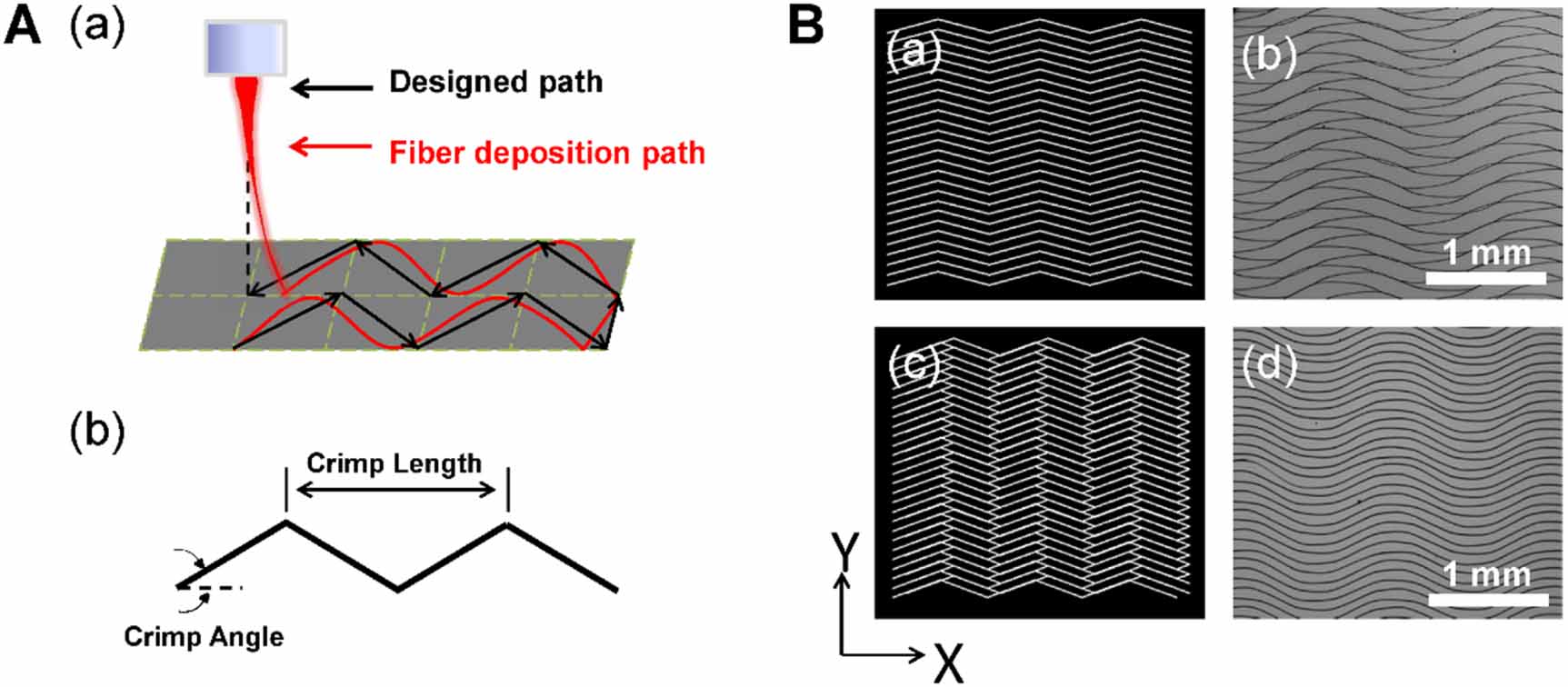
In this study, crimped microfiber patterns were fabricated by MEW under a writing speed higher than the CTS, and the deposition track of electrified jet was controlled by a G-code to follow a triangle wave pattern. During MEW process, the charged polymer jet is generally found to locate a short distance behind the nozzle position when it contacts the collector [29]. Due to this 'jet lag', the fiber placement would be significantly affected when the translation direction is changed along a non-linear printing path. As shown in figures 1(A)(a) and (B)(a), (b), the MEW pattern controlled by a G-code of paralleled crimped lines (crimp length of 2 mm; crimp angle of 20°) turned out to be unparallel and disordered. Therefore, in order to minimize the effect of the jet lag, the designed printing trajectory was deliberately offset a small distance compared with figure 1(B)(a), as shown in figure 1(B)(c), which resulted into more controllable and ordered crimped fiber patterns (figure 1(B)(d)).
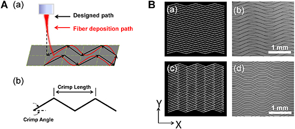
Figure 1. (A) Schematic diagram demonstrating the 'jet lag' during MEW of crimped patterns (a); definition of crimp angle and crimp length in the printed crimped patterns (b). (B) Designed parallel crimped pattern (a) and the resulted disordered pattern (b); optimized designed pattern with a small offset for minimizing the jet lag (c) and the resulted ordered pattern (d).
Download figure:
Standard image High-resolution imageNext, since the angle of the flightpath of the jet is highly determined by air pressure and the movement speed of collector [30], the effect of air pressure and collector speed was studied to further optimize the printing process. Figures 2(A)–(D) show the effect of air pressure on fiber deposition. When the air pressure was adjusted from 8 to 20 kPa, the angle of the flightpath was found to be significantly increased (figure 2(D)), which was mainly resulted by the change of jet velocity. Under the pressure of 8 and 12 kPa, it was observed that some parts of the adjacent fibers stuck together, leading to the disordered patterns with different distances between adjacent fibers. With the continued increase of air pressure, desired crimped micropatterns with almost consistent fiber spacing can be obtained, and 16 kPa resulted into much narrower distribution of fiber spacing compared with 20 kPa, suggested the more orderly pattern (figures 2(B) and (C)). On the other hand, the effect of collector speed on the morphology of MEW crimped micropatterns was similar, also by the influence on the angle of flightpath (figures 3(A)–(D)). After optimization, the MEW crimped pattern printed at the collector speed of 7 mm s−1 showed the most uniform fiber spacing and the best pattern morphology. Therefore, 16 kPa of air pressure and 7 mm s−1 of collector speed were chosen for the printing of the following crimped patterns.

Figure 2. (A) Photographs of the jet profile, under the air pressure of 8, 12, 16 and 20 kPa. (B) SEM images and (C) spacing distribution of the MEW crimped fiber patterns under different air pressures. (D) Angle of flightpath at 8, 12, 16 and 20 kPa.
Download figure:
Standard image High-resolution image
Figure 3. (A) Photographs of the jet profile under the collector speed of 6, 7, 8 and 9 mm s−1. (B) SEM images and (C) spacing distribution of the MEW crimped fiber patterns under different collector speed. (D) Angle of flightpath at 6, 7, 8 and 9 mm s−1.
Download figure:
Standard image High-resolution image3.2. Effect of crimp angle and fiber spacing on cells orientation
Since a highly cell alignment is present in the native ligament tissue, cellular orientation is a key point in the ligament tissue engineering [1]. Meanwhile, the crimp angle of the collagen fibrils in the ligament also fluctuates with respect to gender and age [31]. In our work, the crimped fiber micropatterns with different preset crimp angles from 0° to 30° and fixed inter-fiber spacing of 100 μm and crimp length of 2 mm were fabricated, as shown in figure 4(A). All the micropatterns were composed of smooth crimped fibers with a similar fiber diameter of 10.69 ± 1.51 μm (figure 4(B)(a)). After measurement, the crimp angle of the achieved crimped fibers was almost in line with expectations and showed good consistency with a small standard deviation less than 2° (figure 4(B)(b)), indicating the high precision and stability of the MEW crimped fiber fabrication approach. Overall, the fabricated crimped fibers possess the parameters comparable to the in vivo natural collagen fibers in ligament [12], which suggested the good reference significance of the MEW crimped fiber patterns for mimicking the ligament structure.
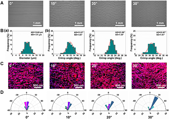
Figure 4. (A) SEM images, (B)—(a) fiber diameter distribution and (B)—(b) crimp angle distribution of the MEW crimped fiber patterns with different crimp angles. (C) Immunofluorescence staining images of NIH-3T3 cells on the crimped fiber patterns with different crimp angle after 48 h of culture. Cytoskeleton was stained with phalloidin (red); nuclei were stained with DAPI (blue). (D) Distribution of the angle between the main direction of the fibers and the long axis of the cells' nuclei on the crimped patterns with different crimp angle.
Download figure:
Standard image High-resolution imageTo study the effect of crimp angle on cell orientation, NIH/3T3 fibroblasts were cultured on the micropatterns with crimp angle of 0°, 10°, 20° and 30° respectively and characterized by cytoskeleton immunostaining after 2 d of culture. As shown in figure 4(C), the cytoskeleton stained with Phalloidin-TRITC showed obvious alignment with MEW fibers, indicated that both straight and crimped fibers showed obvious guidance effect on cell orientation and morphology. The alignment was further quantitatively evaluated by measuring the orientation angle of cells, i.e. the angle between nuclei direction and the main direction of fibers. The statistical results showed that cell orientation angle and fiber crimp angel exhibited good consistency (figure 4(D)). For the 0° micropattern, the nuclei angles of cells were close to 0°. As the crimp angle increased from 0° to 30°, the orientation angle of cells enlarged accordingly. Interestingly, it was also found that the alignment effect of cells was obviously enhanced on the crimped pattern with larger crimp angle, which could be probably explained by the greater degree of restriction for cell spreading. The results suggested that the orientation growth feature of cells in the in vivo ligament tissue could be mimicked by using the MEW crimped fibers.
Considering that fiber spacing is an important parameter for efficient cell alignment guidance [32], MEW crimped micropatterns with different fiber spacings were fabricated to study the effect on cell morphology. Figure 5(A) shows the fabricated crimped fiber micropatterns with a fixed crimp angle of 20° and preset fiber spacing of 50, 100 and 200 μm. By using the optimized processing parameters, all of the three kinds of patterns showed relatively good morphology. Specially, the crimped micropatterns with preset fiber spacing of 100 and 200 μm showed more stable morphology with much smaller standard deviation of fiber spacing (98.98 ± 7.07 and 199.69 ± 6.42 μm) than that of 50 μm (49.84 ± 18.42 μm). Previously Vaquette et al also achieved crimped fibers by MEW and attempted to reduce the fiber spacing, however, uncontrolled fiber stacking and inaccurate deposition would happen once the fiber interdistance was smaller than 200 μm due to the charge build up effect [7]. In our study, after the optimization of the MEW processing parameters, improved crimped fiber micropatterns with fiber spacing small to 50 μm can be achieved, which would be more favourable for cell alignment as previously reported [33–35].
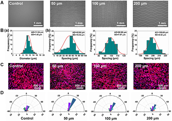
Figure 5. (A) SEM images, (B) fiber diameter distribution (a) and spacing distribution (b) of the MEW crimped fiber patterns with different preset spacings. (C) Immunofluorescence staining images of NIH-3T3 cells on the crimped fiber patterns with different fiber spacings after 48 h of culture. Cytoskeleton was stained with phalloidin (red); nuclei were stained with DAPI (blue). (D) Distribution of the angle between the main direction of fibers and the long axis of the cells' nuclei.
Download figure:
Standard image High-resolution imageThe effect of fiber spacing on cell alignment was then studied also by cytoskeleton staining, as shown in figure 5(C). A plain substrate without any fiber was set as a control group. Compared with the control group, the skeleton of NIH/3T3 cells showed different levels of alignment to the crimped micropatterns with fiber spacing of 50, 100 and 200 μm. As the fiber interdistance became larger, the cell alignment effect of the micropatterns was observed to be weakened. As expected, the micropattern with a fiber spacing of 50 μm exhibited the strongest guidance effect on cell orientation than that with spacing of 100 and 200 μm. Figure 5(D) shows the statistical result of the cell orientation angle, which is consistent with the observation. It could be attributed to that larger fiber spacing provided more free space for cells to spread, and accordingly the confinement effect of fibers on cells was limited.
In short, the MEW crimped fiber micropatterns with different crimp angles (0°–30°) and fiber spacings (50–200 μm) could be successfully fabricated by using the optimized processing parameters, and both of them showed certain influence on the guidance of cell orientation.
3.3. Osteogenic activity study of MEW grid micropatterns
The grid micropatterns fabricated by MEW were applied for the construction of the bone compartment in bone–ligament interface. In consideration of the significant influence of surface topography and parameters of substrate on osteogenesis [36, 37], the grid micropatterns with three different preset fiber spacings (50, 100 and 200 μm) were fabricated to study the osteogenic activity. Figure 6 shows the SEM morphology of the fabricated grid patterns and the statistical results of fiber diameter and spacing. All of the three kinds of patterns showed well-defined grid structure, and the actual pore sizes were measured to be 50.20 ± 2.07, 99.75 ± 2.22 and 199.55 ± 2.59 μm, respectively, which are consistent with our design and demonstrates the accuracy of MEW process. The fiber diameter was measured to be 6.66 ± 1.00, 4.65 ± 0.77 and 4.68 ± 0.77 μm for the grid patterns with fiber spacing of 50, 100 and 200 μm, respectively. To avoid the adhesion between adjacent fibers and ensure the stable writing process, the speed of printing was reduced for the sample with 50 μm of fiber spacing, which resulted into the relatively larger fiber diameter.

Figure 6. (A) SEM images, (B) fiber diameter distribution and (C) pore size distribution of the MEW grid fiber patterns with different preset fiber spacings (50, 100 and 200 μm).
Download figure:
Standard image High-resolution imageALP is a widely used marker of the osteogenic phenotypes [38, 39], and was selected to study the effect of the grid micropatterns on osteogenesis. The above prepared grid micropatterns with different fiber spacings were applied for the culture of human osteoblastic Saos-2 cells. Figure 7(A) shows the representative ALP staining images after 7 and 14 d of osteogenic induction. The sample with 50 μm of fiber spacing exhibited much darker blue color compared with the other groups, suggested the more expression of ALP. It was also observed that the color of ALP staining gradually darkened over time. The ALP activity was then further quantitatively compared using an ALP detection kit, as shown in figure 7(B). It indicates that the MEW grid micropatterns with the fiber spacing of 50 μm resulted into the significantly highest expression of ALP compared with that of 100 and 200 μm, and the expression of ALP in each group increased over time.
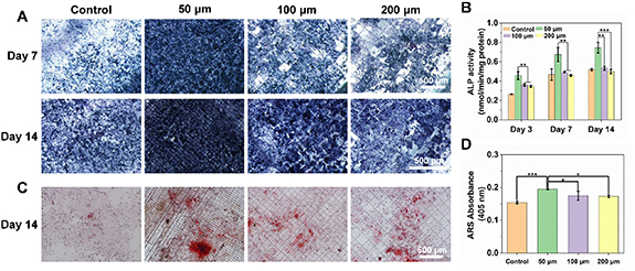
Figure 7. Osteogenesis activity of the MEW grid micropatterns with different fiber spacings (50, 100 and 200 μm). (A) ALP staining images at day 7 and day 14. (B) ALP semi-quantitative results at day 3, day 7 and day 14. (C) ARS staining images at day 14. (D) ARS semi-quantitative results at day 14.
Download figure:
Standard image High-resolution imageThe formation of mineralized nodules is an important sign of calcium mineralization [40, 41]. In order to further characterize the effect of the grid micropatterns on osteogenesis, the mineral deposition of Saos-2 cells grown for 14 d was verified by ARS staining (figure 7(C)). The ARS staining images showed that a denser color and higher intensity of ARS staining were found on the grid parttern with fiber spacing of 50 μm compared with the other groups, suggested a higher calcium concentration. After dissolving the calcium nodules with perchloric acid, the ARS activity was further quantitatively analyzed by the absorbance at 405 nm (figure 7(D)). The ARS absorbance results also showed that 50 μm group exhibited much higher ARS activity than the other groups, while the grid patterns with fiber spacing of 100 and 200 μm showed slightly enhanced ARS value compared with the control group, which was consistent with the results of the staining images.
Both the ALP activity and calcium mineralization results confirmed that the MEW grid micropatterns exhibited greater mineralization and better osteogenesis activity compared with control, expecially the pattern with 50 μm of fiber spacing, which could be attributed to the 3D topography of the micropatterns and the resulted increased specific surface area for cell growth.
3.4. Cell co-culture and bone–ligament interface formation
In order to form bone–ligament interface structure, grid-crimp micropatterns with the fiber spacings of 50, 100, and 200 μm were fabricated by MEW, as shown in figure 8(A). The crimp angle for the micropatterns was set to be 20°, which is comparable to those in the native ligament [12]. The whole structure was obtained by printing the crimp micropattern (ligament region) and the grid micropattern (bone region) alternately, and an interface region was generated between crimp and grid regions and composed of both crimped fibers and grid structure. The SEM morphology of the MEW triphasic structure was shown in figure 8(A). It has been reported that the average width of the interface cartilage area is generally around 300–800 μm [42]. In order to ensure the comparability of cell migration between groups, the length of the interface region was controlled to be similar in this work, which was measured to be around 1 mm for all the triphasic structures with different fiber spacings (figure 8(B)).
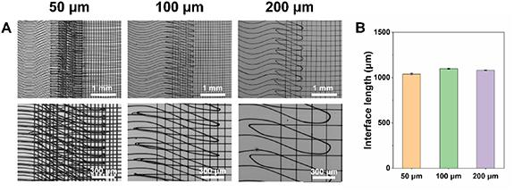
Figure 8. (A) SEM images and (B) interface length of the MEW grid-crimp micropatterns with different preset fiber spacings (50, 100 and 200 μm).
Download figure:
Standard image High-resolution imageNIH/3T3 fibroblasts and Saos-2 osteoblastic cells were seeded on the surface of the ligament region and the bone region, respectively. Prior to cell seeding, NIH/3T3 cells and Saos-2 cells were fluorescently dyed in green and red by CMFDA and CM-DIL, respectively. The fluorescence images after 1 d of culture were shown in figures 9(A)–(C). Both the green NIH/3T3 cells and red Saos-2 cells can be observed to adhere to the surface of the corresponding micropatterns, and both crimped fibers and grid structure showed a certain guidance effect on the orientation of cells (figures 9(A)–(C)). After 3 more days of culture, the cell density in both ligament region and bone region increased significantly due to cell proliferation (figures 9(D)–(F)). NIH/3T3 cells in ligament region showed more obvious alignment along the direction of the crimped fibers, while the orientation of Saos-2 cells in bone region was also certainly affected by the grid structure. Especially the alignment effect of the crimp micropattern with fiber spacing of 50 μm on NIH-3T3 cells was more significant than that with larger fiber spacings, which is consistent with our previous results in section 3.2. Meanwhile, cells in bone region and ligament region were observed to migrate toward the center interface region. And both NIH/3T3 cells and Saos-2 cells migrated faster on the MEW triphasic structure with smaller fiber spacing. Two kinds of cells were found to meet together in the interface region of the micropattern with 50 μm of fiber spacing, however, there was little cells observed in the interface region of the structure with 200 μm of fiber spacing. The difference of cell migration speed might be resulted by the contact guiding effect of the micropattern, as reported previously [43, 44]. Smaller spacing has more obvious effect on the orientation induction of cells, which enhances the deformation of cells along the direction of fibers and accelerates the migration of cells along the direction of fibers. The cell proliferation behavior on the grid-crimp micropatterns was studied by CCK-8 assay, as shown in figure S2 (available online at stacks.iop.org/BF/14/025008/mmedia). The optical density values increased with time and there was no significant difference between the groups with different fiber spacing, which suggested that the spacing showed little influence on cell proliferation.

Figure 9. Images of the fluorescent-labeled NIH/3T3 cells (green) and Saos-2 cells (red) on the crimp micropattern (ligament region), the grid micropattern (bone region) and the in-between interface region at day 1 and day 3.
Download figure:
Standard image High-resolution image3.5. Scaffold preparation and mechanical properties
In this section, we attempted to generate 3D bone–ligament interface scaffold using the fabricated MEW grid-crimp micropatterns. Firstly, the printed flat micropatterns were easily separated from ITO glasses by immersed in ethanol. After drying, the free-standing pattern was rolled up into a tubular scaffold by using a sterile rod. Figures 10(A) and (B) show the photographs of the MEW triphasic micropatterns on ITO glasses and the generated tubular scaffolds with different fiber spacings (50, 100 and 200 μm), respectively. The triphasic structure of the scaffolds can be clearly distinguished, and the scaffold with the fiber spacing of 200 μm looked much sparser than that of 50 and 100 μm. From the SEM images of the scaffolds (figure 10(C)), crimped region, grid region and the interface region can be observed, and the generated tubular scaffolds were formed by plenty of highly ordered fibers with interconnected and multi-layered pore structures. The rolled-up tubular scaffolds retained the well-organized triphasic structure and the morphology of the MEW grid-crimp micropatterns, which would provide corresponding topographical guidance for the behavior of cells in different regions in the future possible bone–ligament interface tissue engineering applications.
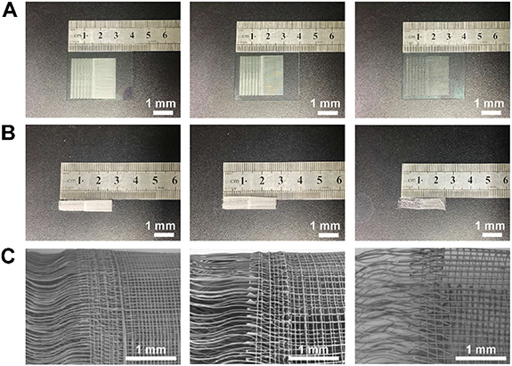
Figure 10. (A) Macroscopic view of the grid-crimp micropatterns with the fiber spacing of 50, 100 and 200 μm, respectively. (B) Macroscopic view of the rolled up tubular scaffolds with different fiber spacings. (C) SEM images of the triphasic scaffolds with different fiber spacings.
Download figure:
Standard image High-resolution image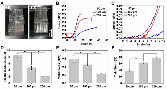
Figure 11. Tensile properties of the triphasic scaffolds. (A) The photographs of the triphasic scaffold before (a) and after (b) stretching during uniaxial tensile test. (B) Stress–strain curves of the triphasic scaffolds with different fiber spacings. (C) Toe region of the stress–strain curves (the enlarged view of the region inside the red frame of figure 11(B)). (D) Elastic modulus, (E) yield stress and (F) yield strain of the triphasic scaffolds.
Download figure:
Standard image High-resolution image
Next, the mechanical properties of the fabricated tubular scaffolds were evaluated by uniaxial tensile testing, as shown in figure 11(A). Figure 11(B) shows the representative stress–strain curves of the scaffolds with different fiber spacings (50, 100 and 200 μm). In the stretching process, the crimped region strained firstly which can also be observed during stretching (figure 11(A)) and resulted into a characteristic toe region with little change of the stress during elongation up to around 5% followed by a progressive stiffening process with an increasing Young's modulus before 8%–10% of elongation (figure 11(C)). For comparison, single crimped fibers with different crimp angles from 0° to 30° were also applied for tensile testing, as shown in figure S1. There was also the similar toe region during the initial stretching for all the crimped fibers, and the toe region increased as the crimp angle was enlarged. In contrast, the toe region was found to be absent in the curve of straight fibers (0°). This phenomenon was in line with many previous studies of crimped structure and also consistent to the native ligament/tendon tissue [31, 45–48]. The non-linear toe region was related to the straightening of the fiber crimps, and the magnitude of the region was also comparable to the native ligament (7%–16%) [47]. After crimp-unfolding, the further stretching resulted into a linear elastic deformation region, then plastic deformation region and the final fracture, which is similar to the stress–strain curves of the previously reported MEW PCL straight fiber scaffolds [19, 27, 32]. The elastic modulus of the scaffolds with different fiber spacings was also calculated and compared (figures 11(D)–(F) and table 1). The scaffold with the fiber spacing of 50 μm showed the largest elastic modulus and yield stress but the smallest yield strain. As fiber spacing was enlarged, both elastic modulus and yield stress reduced, while yield strain increased. Specially, the scaffold with fiber spacing of 100 and 200 μm exhibited the yield strain of 31.3 ± 1.41% and 38.78 ± 0.47, respectively, which is accordant with the yield strain (30%–45% depends on age) of human anterior cruciate ligament [49]. Besides, the elastic modulus of the fabricated scaffolds was close to that of native anterolateral ligament (reported to be 1.2 MPa), and the grid-crimp scaffold could also be fabricated using other polymers with different modulus to meet the mechanical requirements of the application in the other specific types of native ligaments [31].
Table 1. Tensile properties of the triphasic scaffolds.
| Fiber spacing | Elastic modulus (MPa) | Yield stress (MPa) | Yield strain (%) |
|---|---|---|---|
| 50 μm | 8.48 ± 0.62 | 0.59 ± 0.08 | 18.90 ± 1.85 |
| 100 μm | 4.73 ± 0.57 | 0.45 ± 0.03 | 31.30 ± 1.41 |
| 200 μm | 2.07 ± 0.15 | 0.22 ± 0.01 | 38.78 ± 0.47 |
Hence, the MEW grid-crimp tubular scaffold possessed mechanical graded properties, which are similar to the native bone–ligament interface and would offer appropriate mechanical cues for the regeneration of bone–ligament interface during the further tissue engineering applications.
Therefore, the MEW grid-crimp tubular scaffold could meet both the morphological and mechanical requirements of the native bone–ligament interface tissue, showing good potential to be utilized for bone–ligament interface tissue engineering.
4. Conclusion
In summary, a grid-crimp multiphasic micropattern was successfully fabricated by MEW to mimic the structure of native bone–ligament interface. The strategy for the fabrication of crimped fiber micropatterns was developed and the processing parameters including air pressure and collector speed were optimized. The crimped micropatterns with crimp angle from 0° to 30° and fiber spacing ranging from 50 to 200 μm were achieved, and both of them affected cell alignment to different degrees. MEW grid micropatterns with the fiber spacing from 50 to 200 μm were fabricated and showed better osteogenesis activity than the control, especially for the pattern with 50 μm of spacing. The grid-crimp micropatterns with different fiber spacings were applied for the co-culture of NIH/3T3 cells and Saos-2 cells, and the cell migration results demonstrated that smaller fiber spacing resulted into faster migration speed and earlier cell encounter in the interface region. A 3D tubular triphasic scaffold was finally generated by rolling the MEW grid-crimp micropattern up, showing both structural and mechanical similarity to the native bone-to-ligament tissue, which was expected to be utilized as a novel scaffold for the in vivo bone–ligament interface regeneration studies in our future research.
Acknowledgments
This work was supported by National Natural Science Foundation of China (Grant Nos. 81801830, 82001983 and 62171142), Guangdong Basic and Applied Basic Research Foundation (Grant No. 2019A1515011363, 2019A1515111202 and 2021A1515011908), Science and Technology Program of Guangzhou, China (Nos. 202102020645 and 202002030269), Project of Science and Technology of Foshan City (No. 2015IT100152), University Innovation and Entrepreneurship Education Major Project of Guangzhou City (No. 201709P05) and Jihua Laboratory Foundation of Guangdong Province Laboratory of China (No. X190071UZ190).
Data availability statement
The data that support the findings of this study are available upon reasonable request from the authors.