

Abstract
Cell alignment plays an essential role in cytoskeleton reorganization, extracellular matrix remodeling, and biomechanical properties regulation of tissues such as vascular tissues, cardiac muscles, and tendons. Based on the natural-oriented features of cells in native tissues, various biomimetic scaffolds have been reported with the introduction of well-arranged ultrafine fibers to induce cell alignment. However, it is still a challenge to fabricate scaffolds with suitable mechanical properties, biomimetic microenvironment, and ability to promote cell alignment. In this paper, we propose an integrated 3D printing system to fabricate multi-scale hierarchical scaffolds combined with meso-, micro-, and nano-fibrous filaments, in which the meso-, micro-, and nano-fibers fabricated via fused deposition modeling, melt electrospining writing, and solution electrospining can provide structural support, promote cell alignment, and create a biomimetic microenvironment to facilitate cell function, respectively. The plasma surface modification was performed improve the surface wettability of the scaffolds by measuring the contact angle. The obtained in vitro biological results validate the ability of multi-scale hierarchical scaffolds to enhance cell adhesion and proliferation, and promote cell alignment with the guidance of the aligned microfibers produced via melt electrospining writing in hierarchical scaffolds.
Export citation and abstract BibTeX RIS
1. Introduction
Cell alignment has been widely investigated in native tissues, such as blood vessels [1], cardiac tissue [2], neurons [3], and tendons [4]. For instance, the orientation of monolayered vascular endothelial cells along the direction of blood flow in native blood vessels is critical to the regulation of anti-thrombogenic reactions and biological signaling events [5, 6]. In addition, multiple layers of aligned cardiomyocytes in the native myocardium are essential for synchronic contraction and efficient blood pumping [7, 8]. Therefore, to restore tissue functions and engineer in vitro models for tissues with naturally oriented structures, it is necessary to realize in vitro cell alignment.
Various approaches, including topographical patterns [9], surface chemical treatment [10], and mechanical cues [11], have been explored to achieve in vitro cell alignment. In addition, tissue engineering scaffolds have provided a promising approach to regenerate functional tissue substitutes [12, 13]. With advances in scaffold fabrication technologies, it is feasible and effective to enhance cell alignment with the introduction of topographical cues in scaffolds. Anuradha et al reported that scaffolds with aligned fibers could facilitate the alignment of Schwann cells better than scaffolds with random fibers [14]. Accordingly, various techniques, such as self-assembly, solution blow spinning, electro-hydrodynamic jet printing, and melt electrospining writing (MEW), have been applied to fabricate aligned micro- or nano-scale fibers [15–18]. Among these methods, MEW has emerged as a simple and versatile technology to prepare microns fibers, and has exhibited an extraordinary ability to control the placement of fibers comprising synthetic polymers, with diameters ranging from 1 to 20 μm [19, 20]. Mao et al [8] fabricated highly aligned biomimetic cellular architectures via MEW, which demonstrated significant potential for effective cell alignment. Although highly oriented melt electrospun micro-fibers can facilitate cell alignment, the main limitations of MEW scaffolds are circumscribed scaffold dimensions, as well as insufficient cell adhesion and migration owing to the difference between the oriented micro-fiber arrangement and complex native extracellular matrix (ECM) [21, 22].
Therefore, besides a potential ability to promote cell alignment, scaffolds should also possess suitable mechanical properties and biomimetic microenvironment for cell attachment, infiltration, and migration. Different fabrication technique, including fused deposition modeling (FDM) [23–25], solution electrospining (SE) [26, 27], freeze drying [28, 29], and phase separation [30–32], have been proposed in previous studies to develop biomimetic scaffolds for tissue-engineered models. Among these methods, FDM has been validated to be an effective technique for fabricating scaffolds with relatively large structures and pores (generally greater than 100 μm) to provide mechanical support and nutrition transportation [25, 33]. SE has been widely adopted and verified to be a versatile technology and economical solution for producing nano-fiber to mimic the structure of native ECM [34, 35]. With the combination of FDM and SE, the challenges faced by each technique could be obviated, as FDM scaffolds lack a biomimetic microenvironment for cell adhesion, and SE scaffolds exhibit intrinsic inferior mechanical support. Park et al [36] reported a hierarchical 3D polymer scaffold comprising melt-plotted polycaprolactone (PCL) strands and PCL nano-fibers, which exhibited controlled mechanical properties and improved cell attachment and proliferation.
The purpose of this study is to fabricate multi-scale hierarchical scaffolds with desirable mechanical properties, a biomimetic microenvironment, and the ability to promote cell alignment. Accordingly, we developed a multi-scale integrated printing system with a combination of the respective advantages of FDM, SE, and MEW techniques. Furthermore, we fabricated novel multi-scale hierarchical scaffolds with meso-, micro-, and nano-scale fibers, with diameters ranging from hundreds of microns, several microns, and hundreds of nanometers. In addition, an oxygen plasma treatment was performed to improve the hydrophilicity of the scaffolds. Human umbilical vein endothelial cells (HUVECs) and C2C12 myoblast cells (C2C12 cells) were selected to separately assess cell behavior on multi-scale hierarchical scaffolds. The biocompatibility of multi-scale hierarchical scaffolds was investigated via LIVE/DEAD staining and cell counting Kit-8. The morphology of cells on the different scaffolds was analyzed via scanning electron microscopy (SEM) and cytoskeleton staining. The above biological experiments indicated that the multi-scale hierarchical scaffolds possessed optimal biocompatibility and the ability to enhance cell alignment.
2. Materials and methods
2.1. Materials
PCL (average Mn 80 kDa) and 1,1,1,3,3,3-hexafluoro-2-propanol (HFIP, 99+%) were purchased from Sigma-Aldrich (St. Louis, MO, USA). Collagen type I was supplied by Shanghai Yuanye Biotechnology Co., Ltd (Shanghai, China). All other chemicals and reagents used were of analytical grade. Every chemical in this study was used as received without further purification.
2.2. System configuration for multi-scale integrated printing
In this study, we developed a multi-scale integrated printing system device to fabricate multi-scale hierarchical scaffolds. As illustrated in figure 1(a), the printing system consists of a control center, an x–y–z motion system, and a delivery system. The delivery system consists of the FDM, MEW, and SE systems. FDM, MEW, and SE three different systems are integrated on a printing platform at the same time. In addition, the principles of the three systems are presented in figure 1(b).
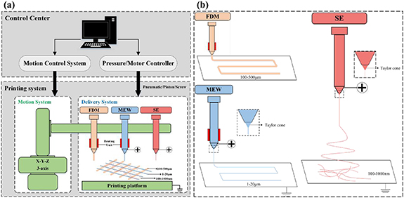
Figure 1. Custom-made multi-scale integrated printing system. (a) Configuration of the multi-scale integrated printing system. (b) Schematic diagram of the FDM, MEW, and SE techniques. FDM: fused deposition modeling; MEW: melt electrospining writing; SE: solution electrospining.
Download figure:
Standard image High-resolution imageIn the FDM system, PCL pellets were loaded into a stainless charging barrel, and molted by a heater attached to the barrel. A pneumatic device was connected to the barrel to extrude the PCL melt into fibers through a nozzle. Based on the FDM system, in addition to adjust the nozzle diameter and printing distance between the nozzle and platform, a high voltage was applied between the nozzle and the platform, and then an electrified molten jet with a micron diameter was developed from the Taylor cone in the MEW process. In the SE system, PCL and collagen type I solution were loaded into a hypodermic syringe and extruded through a needle tip at a constant rate using a syringe pump connected to the syringe. Similarly, a high voltage was applied between the needle tip and the platform. A jet was stretched from the Taylor cone and elongated into fibers of several hundred nanometers. Generally, FDM and MEW fibers can be deposited on the platform in an accurate and controllable manner, whereas SE fibers are produced randomly to fabricate electrospun mats.
2.3. Fabrication of multi-scale hierarchical scaffolds
Prior to the fabrication of multi-scale hierarchical scaffolds, the preliminary investigation of each system was conducted, and FDM, MEW, and SE scaffolds were prepared. In the FDM process, printing parameters, such as air pressure, heating temperature, nozzle diameter, distance between the nozzle and the platform, and moving speed of the platform, were fixed at 500 kPa, 100 °C, 800 μm, 0.5 mm, and 1 mm s–1, respectively. For the MEW printing, the air pressure, nozzle diameter, distance between the nozzle and platform, and moving speed of the platform, were adjusted to 15 kPa, 300 μm, 3 mm, and 5 mm s–1, respectively. A high voltage (3.5 kV) was applied between the nozzle and the platform. To fabricate sub-microscale SE fibers, PCL/collagen solution was prepared by dissolving 10 g PCL and 7.5 g collagen in 100 ml HFIP, and loaded into a 2.5 ml hypodermic syringe. The process parameters for the SE technique, such as feeding rate, distance between the needle tip (22 G) and the platform, and applied voltage were set as 2.0 ml h–1, 100 mm, and 12 kV, respectively. In this study, multi-scale hierarchical scaffolds with micro- and nano-scale fibers were fabricated via the structured integration of FDM, SE, and MEW fibers. To further demonstrate the biological function of multi-scale hierarchical scaffolds, scaffolds consisting of FDM and SE fibers, as well as FDM and MEW fibers, were prepared as control groups.
2.4. Plasma modification and water contact angle measurement of multi-scale hierarchical scaffolds
To improve the hydrophilicity of PCL fibers within multi-scale hierarchical scaffolds, all scaffolds were treated with oxygen plasma (Zepto, Diener Electronic, Germany) at a pressure of 0.02 mtorr and 40 W for 30, 60, and 90 s, respectively. Subsequently, for the three types of scaffolds (FDM + SE + MEW, FDM + SE, and FDM + MEW) treated with plasma for 0, 30, 60, and 90 s, respectively, sessile drop contact angle measurements were performed to evaluate the surface hydrophilicity (water wettability) of the scaffolds using a contact angle goniometer (Dataphysics, OCA 15, Germany). Water droplet (2 μl) was deposited on the surface of the scaffolds, and the contact angle was recorded within 5 s. The water contact angle of each sample was calculated using the average of the values measured from three spots.
2.5. Structural characterization of multi-scale hierarchical scaffolds
The morphologies of the scaffolds were characterized via SEM analysis (ZEISS GeminiSEM 300, Germany) at an accelerating voltage of 5 kV. Before the SEM observation, the samples were sputter-coated with gold for 60 s. The diameters of the scaffold fibers were measured using the open access software platform FIJI (Image J) based on the SEM images obtained.
2.6. Cell culture and assessment of multi-scale hierarchical scaffolds
2.6.1. Cell viability and proliferation
In this study, HUVECs and C2C12 cells purchased from China Infrastructure of Cell Line Resources in Beijing were selected and adopted for cell behavior assessment on multi-scale hierarchical scaffolds. HUVECs and C2C12 cells were cultured in Dulbecco's modified eagle medium (DMEM) supplemented with 10% fetal bovine serum and 1% MEM non-essential amino acids. Before seeding the cells, the scaffolds were sterilized in 75% ethyl alcohol for 3 h, washed thrice in phosphate buffer saline (PBS), and then wetted in culture medium for 12 h. Scaffolds were placed in 24-well tissue culture plates, while HUVECs (passage 15) and C2C12 cells (passage 18) were seeded onto the scaffolds at densities of 1.0 × 10⁵ and 5.0 × 10⁴ cells per scaffold in a 1 ml culture medium, respectively. The scaffolds were incubated at 37 °C with 5% CO2. The culture medium was altered daily.
For HUVEC-seeded scaffolds, cell viability was investigated using a LIVE/DEAD cell double staining kit (Dojindo, Japan) on days 1 and 7, according to the manufacturer's instructions. Briefly, different groups of scaffolds were washed thrice in PBS, and then transferred into a new 24-well plate. Next, 500 μl of the PBS solution containing 2 μM calcein AM and 4.5 μM propidium iodide was added to each scaffold, incubated for 30 min in the dark, and washed thrice in PBS to remove residual reagents. Finally, the scaffolds were observed under a laser confocal microscope (Nikon A1, Japan). To analyze cell proliferation within the scaffolds, a cell counting Kit-8 (CCK-8, Dojindo, Japan) was applied on days 1, 4, and 7 according to the manufacturer's protocol. For C2C12 cells-seeded scaffolds, cell viability tests were performed on days 1 and 5, while cell proliferation was analyzed on days 1, 3, and 5. The specific operation was consistent with the above tests.
2.6.2. Cell morphological analysis
To further analyze the morphology of the HUVECs and C2C12 cells on the different scaffolds, cytoskeleton staining was performed after culturing for 7 and 5 d, respectively. In summary, the samples were rinsed thrice in PBS, fixed with a 4% paraformaldehyde solution, washed again in PBS, and treated with 0.1% Triton X-100. After the samples were stained in the dark with phalloidin (red) and 4', 6-diamidino-2-phenylindole (DAPI, blue) at room temperature, the samples were visualized using a laser confocal microscope.
In addition, SEM analysis was conducted to observe the cell morphology. Cell-seeded scaffolds were fixed with 2% paraformaldehyde and 2.5% glutaraldehyde in a 0.1 M phosphate buffer for 1 h at room temperature. The samples were washed in PBS and dehydrated in 30%, 50%, 70%, 90%, and 100% graded alcohol solutions for 20 min each. Then, the scaffolds were air-dried in a desiccator and sputter-coated with gold for 60 s before SEM observation (ZEISS GeminiSEM 300, Germany).
2.7. Statistical analysis
Experimental data was presented by 'mean ± standard deviation' with samples n = 4. The statistical analysis software GraphPad Prism 8.0 was adopted for the Student's t-test.
3. Results and discussion
3.1. Design and fabrication of multi-scale hierarchical scaffolds
Tissue engineering scaffolds have been widely investigated and applied as a reliable and promising technique for fabricating in vitro templates for tissue regeneration [37]. Generally, scaffolds should exhibit sufficient mechanical properties, biocompatibility, and preference for cell adhesion [38]. Scaffold properties should be consistent with the requirements of target tissues, and regulated by selecting proper fabrication techniques. For blood vessels, myocardium, and other tissues with multi-scale hierarchical structures and cell alignment arrangement characteristics, it is difficult to recapitulate the in vivo milieu and achieve cell alignment in vitro using scaffolds prepared by conventional FDM and SE techniques. Furthermore, based on the naturally oriented cells in native tissues, such as blood vessels and cardiac tissues, scaffolds with aligned micro- or nano-scale fibers have been developed and validated as efficient means for promoting cell alignment [13, 39, 40]. Scaffolds with aligned micro-fibers fabricated via the MEW method, have exhibited significant potential for facilitating cell alignment [8, 41, 42]. Therefore, to develop tissue-engineered models, which could provide appropriate structural support and biomimetic microenvironment, as well as the potential to realize in vitro cell alignment, we proposed a multi-scale hierarchical scaffold fabricated with the combination of FDM, SE, and MEW techniques.
In this study, the structural design of multi-scale hierarchical scaffolds is presented in figure 2. Multi-scale hierarchical scaffolds are composed of meso-, micro-, and nano-scale fibers. Meso-scale fibers with diameters of several hundred micrometers can provide sufficient and adjustable structural support by altering the diameter and interval of the meso-fibers. Well-organized and aligned micro-scale fibers with diameters of several microns have the potential to guide cell orientation. Randomly arranged nano-scale fibers with diameters of several hundred nanometers can mimic the structure of ECMs to facilitate cell adhesion and proliferation. The perpendicular meso-fibers were placed in the bottom layer, on which the randomized nano-fibers and aligned micro-fibers were deposited sequentially. Micro-fibers were positioned on top of the nano-fibers to avoid obstructions by a compact nano-fibrous structure, and the inability to regulate cell orientation.

Figure 2. Structural design and fabrication procedure of multi-scale hierarchical scaffolds.
Download figure:
Standard image High-resolution imagePrior to fabricate multi-scale hierarchical scaffolds, meso-, micro-, and nano-scale fibers with different diameters ranging from hundreds of microns to hundreds of nanometers were separately developed via the FDM, MEW, and SE techniques. As shown in tables S1, S2, and S3 (supplementary material (available online at stacks.iop.org/BMM/16/045047/mmedia)), the effect of experimental parameters on the fiber diameter was investigated to determine the proper fabrication parameters of meso-, micro-, and nano-scale fibers. As shown in table S1 and figure S1, the result indicates that the fiber diameter increased with increasing air pressure and the inner diameter of nozzle, while it decreased with increasing printing speed. The average fiber diameter of FDM fibers ranges from 315.67 to 777.14 μm. In this study, the fiber diameter of FDM fibers was designed about 500 μm. Therefore, printing parameters, including air pressure, nozzle diameter, and moving speed of the platform, were selected as 500 kPa, 800 μm, and 1 mm s−1 (group A in table S1), respectively. It was reported that a higher voltage and a lower air pressure could facilitate the stability of MEW printing process within certain limits [19, 43, 44]. As shown in table S2 and figure S2 (supplementary material), the fiber diameter of MEW fibers increased with increasing voltage and air pressure, while it decreased with increasing printing speed. Therefore, it is feasible to acquire the MEW fiber with relatively large and stable fiber diameter by selecting a higher voltage and moderate air pressure. To balance the printing accuracy, efficiency, and the fiber diameter for the MEW printing, the voltage, air pressure, and moving speed of the platform, were adjusted to 3.50 kV, 15 kPa, and 5 mm s−1 (group A in table S2), respectively. As shown in table S3 and figure S3 (supplementary material), the average fiber diameter of SE fibers increased with increasing flow rate and voltage. However, an exceeded voltage may lead to less flight time for the jet to stretch prior to deposition, resulting in deficient solvent evaporation and larger fiber diameter. Relatively, fibers in group 1 showed better surface morphology and dimension accuracy. Therefore, to fabricate neat and steady SE nano-fibers, the electrospining parameters, including feeding rate, and applied voltage were set as 2.0 ml h−1, and 12 kV, respectively.
The SEM images in figure 3(a) present the morphologies of the FDM PCL meso-fibers, which exhibits an average diameter (width) of 508.25 ± 9.48 μm. By applying a high voltage and adjusting the printing parameters based on the FDM technique, MEW fibers were fabricated with a uniform structure (figure 3(b)), and the diameters of the PCL micro-fibers decreased to 6.65 ± 0.55 μm (figure 3(d)), which is approximate to the dimensions of HUVECs and C2C12 cells. In addition, to mimic the structure of the natural ECM, PCL/collagen nano-fibers with an average diameter of 553.97 ± 66.43 nm were randomly deposited in the SE process (figures 3(c) and (e)).

Figure 3. Morphologies of fibers fabricated with the FDM, SE, and MEW techniques. (a) PCL meso-fibers printed in the FDM process. (b) Micro-scale PCL fibers prepared via MEW. (c) Randomly deposited ultrafine PCL/collagen nano-fibers fabricated via SE. (d) Diameters of fibers in FDM, MEW, and SE scaffolds. (e) Distribution of fiber diameters for ultrafine PCL/collagen nano-fibers. The surface morphologies of the fibers were obtained via SEM analysis (ZEISS GeminiSEM 300, Germany).
Download figure:
Standard image High-resolution imageAs illustrated in figure 4, multi-scale hierarchical scaffolds were fabricated by integrating FDM, SE, and MEW fibers. Meso-, nano-, and micro-scale fibers fabricated via FDM, SE, and MEW, were developed in sequence. In the fabrication process, three systems switched automatically, because the change of working position between different systems was added in the printing path planning. Therefore, after FDM fibers were fabricated, SE system moved to the origin of the coordinates automatically. The randomly deposited SE PCL/collagen nano-fibers were electrospun onto the perpendicular patterns of the FDM PCL fibers. Subsequently, MEW system moved to the origin automatically after SE fibers were completed. The highly aligned MEW PCL micro-fibers were deposited in parallel on top of the electrospun nano-fibers. Then, a multi-scale hierarchical scaffold was developed with the combination of one layer of the perpendicular FDM fibers, one layer of random SE fibers, and one layer of MEW fibers. Specifically, the perpendicular FDM fibers include one layer of horizontal FDM fibers and one layer of vertical FDM fibers. Taking the flattening of FDM fibers during printing process and the fusion between the two layers of fibers into consideration, the thickness of the perpendicular FDM fibers was slightly less than twice the average diameter (width) of FDM fibers. The thickness of the perpendicular FDM fibers, SE fibers, and MEW fibers were about 718, 3, and 20 μm, respectively. As shown in figure S4 (supplementary material), scaffolds with different layers were fabricated and exhibited well structural integrity.

Figure 4. Structural schematic diagram and morphologies of (a) FDM + SE, (b) FDM + MEW, and (c) FDM + SE + MEW scaffolds. The structure morphology of scaffolds was conducted via SEM analysis (ZEISS GeminiSEM 300, Germany). FDM + SE scaffolds: scaffolds fabricated with FDM and SE fibers. FDM + MEW scaffolds: scaffolds fabricated with FDM and MEW fibers. FDM + SE + MEW scaffolds: scaffolds fabricated with FDM, SE, and MEW fibers.
Download figure:
Standard image High-resolution imageTo evaluate the effect of the scaffold structure on cell adhesion and cellular behavior, the scaffolds combined with FDM and SE fibers (figure 4(a)), as well as those combined with FDM and MEW fibers (figure 4(b)) were prepared as control groups. To better differentiate the three types of scaffolds, multi-scale hierarchical scaffolds fabricated with FDM, SE, and MEW fibers were depicted as FDM + SE + MEW scaffolds. Accordingly, scaffolds fabricated with FDM and SE fibers, and those fabricated with FDM and MEW fibers, were represented as FDM + SE and FDM + MEW scaffolds, respectively.
3.2. Effect of plasma pretreatment on the surface hydrophilicity and structure of scaffolds
As previously reported, the surface hydrophilicity of scaffolds indicate the wettability of the material surface and affected cell attachment in tissue engineering [45]. In previous studies, PCL fibers exhibited intrinsically inferior hydrophilicity, low surface energy, and the absence of bioactive functional groups, which triggered an interference with cell adhesion and proliferation for the tissue regeneration within the PCL scaffolds [46, 47]. Plasma treatment has proven to be an effective technique for introducing surface roughness and improving the surface hydrophilicity of PCL scaffolds [48]. Eda et al [49, 50] reported a study on the use of oxygen plasma treatment to realize the surface modification of 3D PCL scaffolds, and to further enhance the attachment, proliferation, and differentiation of cells.
Therefore, to improve the hydrophilicity and bioactive properties of scaffolds with PCL fibers, oxygen plasma treatment was performed at treatment times of 30, 60, and 90 s, respectively. To investigate the influence of plasma treatment on surface wettability, the contact angles of different groups of scaffolds were measured. For the three different groups, the contact angle values with/without plasma pretreatment are presented in figure 5. Compared with non-treated samples of the three groups, the surface hydrophilicity of the pretreated scaffolds significantly improved as the plasma treatment time increased from 0 to 90 s. In particular, surface wettability changed significantly as the plasma treatment time increased from 30 to 60 s. In addition, it can be observed that the scaffold hydrophilicity can be effectively enhanced by the introduction of SE PCL/collagen nano-fibers. After the treatment with oxygen plasma, the structures of the scaffolds with SE and MEW fibers were observed via SEM analysis. As illustrated in figure 6(a), the structures of the untreated SE fibers were compact and intact. However, with the increase in plasma treatment time from 30 to 90 s, the structures exhibited varying degrees of damage (figures 6(b)–(d)). In particular, structural damage obviously increased as the treatment time increased from 60 to 90 s. Similar results were also observed for scaffolds with MEW fibers. As illustrated in figure 6(e), the untreated MEW fibers possess uniform and straight structures. After the plasma treatment, the structures gradually became randomized (figures 6(f)–(h)). Similarly, the structures of the MEW fibers were obviously randomized as the treatment time increased from 60 to 90 s.

Figure 5. Contact angle measurements of different groups of scaffolds with/without plasma pretreatment. (a) Contact angles measured by a contact angle goniometer. (b) Water contact angles of each sample measured from three different spots and presented as mean ± standard deviation. Statistical evaluations were performed by paired two-tailed student's t tests. * = p < 0.05, ** = p < 0.01, *** = p < 0.001.
Download figure:
Standard image High-resolution image
Figure 6. Morphologies of scaffolds with/without plasma pretreatment. SEM images of (a) non-treated, and plasma treated SE fibers for (b) 30 s, (c) 60 s, and (d) 90 s. SEM images of (e) non-treated and plasma treated MEW fibers for (f) 30 s, (g) 60 s, and (h) 90 s.
Download figure:
Standard image High-resolution imageTherefore, owing to this trade-off, it is crucial to select an appropriate plasma treatment time. After the comprehensive consideration of the surface wettability and structure of the scaffolds, a plasma treatment time of 60 s was determined in this study. From figure 6, it can be observed that the scaffolds can possess applicable hydrophilicity and steady structures, after the treatment with oxygen plasma for 60 s. Additionally, slight structural damage to the SE nano-fibers can promote cell permeation through the highlighted zone in figure 6(c).
3.3. Cell viability and proliferation
Highly aligned cellular architectures have been observed in many native tissues, such as blood vessels, skeletal muscle, and cardiac tissues [51–53]. HUVECs and C2C12 cells have been intensively adopted to create in vitro vascular, skeletal muscle, and cardiac tissue models [54, 55]. Here, we selected HUVECs and C2C12 cells to investigate the biocompatibility of the multi-scale hierarchical scaffolds via cell viability and proliferation experiments. After the HUVECs and C2C12 cells were seeded in different scaffold groups, live/dead staining and CCK-8 cell proliferation assay were performed, respectively. As illustrated in figures 7(g) and (n), all three kinds of scaffolds exhibit optimal biocompatibility, with approximately five-fold cell proliferation, on days 7 (HUVECs) and 5 (C2C12 cells) compared to the day 1 case. The cellular growth of HUVECs and C2C12 cells in different scaffolds was demonstrated by live/dead staining images in figures 7(a)–(c) (HUVECs, day 1), (d)–(f) (HUVECs, day 7), (h) and (i) (C2C12, day 1), and (k)–(m) (C2C12, day 5).
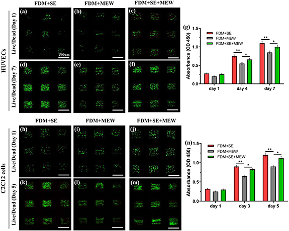
Figure 7. Cell viability and proliferation on scaffolds. (a)–(f) Representative live/dead staining images of HUVEC-seeded scaffold after culture for (a)–(c) 1 d and (d)–(f) 7 d, respectively. (g) Comparison of cell proliferation between HUVEC-seeded FDM + SE, FDM + SE, and FDM + SE + MEW scaffolds. (h)–(m) Representative live/dead staining images of C2C12 cell-seeded scaffold after culture for (h)–(j) 1 d and (k)–(m) 5 d, respectively. (n) Comparison of cell proliferation between C2C12 cell-seeded FDM + SE + MEW, FDM + SE, and FDM + MEW scaffolds. Scale bar: (a)–(f) 500 μm; (h)–(m) 500 μm. * = p < 0.05, ** = p < 0.01.
Download figure:
Standard image High-resolution imageThe obtained cell proliferation results suggest that C2C12 cells provide a more superior proliferation rate than HUVECs, although the number of C2C12 cells seeded on the scaffold was only half that of the HUVECs. From figures 4(b) and 7, it can be observed that the FDM + MEW scaffolds comprise of perpendicular FDM fibers with diameters of several hundred microns and parallelly arranged MEW fibers with diameters of several microns. Compare with FDM + SE and FDM + SE + MEW scaffolds, the interspace among MEW fibers in FDM + MEW scaffold leads to low cell attachment area, and cells can only adhere to the surface of limited MEW fibers. As illustrated in figures 4(a), (c) and 7, and figures S5 and S6 (supplementary material), owing to the introduction of randomly deposited nano-fibers, FDM + SE and FDM + SE + MEW scaffolds can mimic the structure of native ECMs and exhibit a high surface-to-volume ratio structure, thus improving the cell attachment compared to FDM + MEW scaffolds. In addition, the introduction of type I collagen in the nano-fibers further improved the biocompatibility of the scaffolds and promoted cell viability. Moreover, it was determined that HUVECs and C2C12 cells on the FDM + SE and FDM + SE + MEW scaffolds can promote and regulate cell spreading and migration, owing to their large surface area (figure 8). As every coin has two sides, the random PCL/collagen fibers may prevent cell migration in the scaffold, which is the inherent drawback of electrospun scaffolds. In this study, we think the defects of the PCL/collagen nano-fibers cannot obscure the virtues. From the above cell viability and proliferation results, it can be inferred that multi-scale hierarchical scaffolds exhibit sufficient biocompatibility to promote cell adhesion, spreading, and migration, in which PCL/collagen nano-fibers contribute to the enhancement of cell attachment and proliferation.

Figure 8. Cell morphological analysis of multi-scale hierarchical scaffolds. (a)–(c) F-actin/DAPI staining and (d)–(f) SEM images of HUVEC-seeded scaffolds after culturing for 7 d. (g)–(i) F-actin/DAPI staining and (j)–(l) SEM images of C2C12 cell-seeded scaffolds after culturing for 5 d. F-actin (phalloidin, red), DAPI (blue). Scale bar: 100 μm.
Download figure:
Standard image High-resolution image3.4. Cell morphology analysis
To further investigate the morphology and orientation of HUVECs and C2C12 cells in different scaffold groups, phalloidin (red) and DAPI (blue) staining, as well as SEM characterization were performed to present the F-actin cytoskeleton and cellular morphology, respectively. SEM images of samples applied for cell testing was presented in figures S7 ((a1), (b1), and (c1)) (supplementary material). Because of the light transmittance of the scaffold, only cells attached between the FDM fibers in the fluorescence imaged could be observed in figure 8. Therefore, we observed the morphology of different scaffolds after seeded cells, and related results was showed in figures S5–S7 (supplementary material).
As illustrated in figures 8, S5–S7 (supplementary material), the scaffolds were appropriately covered with cells after culturing for 7 (HUVECs) or 5 d (C2C12 cells), especially in the FDM + SE and FDM + SE + MEW scaffolds. For FDM + MEW scaffold, SEM images of cells outside the fluorescence plan were supplemented in figure S7(b3) (supplementary material). In the FDM + MEW and FDM + SE + MEW scaffolds, HUVECs and C2C12 cells were significantly aligned and stretched along with the MEW fibers, while the HUVECs and C2C12 cells were randomly deposited in the FDM + SE scaffolds. As shown in figure S7 (supplementary material), figures S7(a1), (b1), and (c1) presented the morphology of cells attached between FDM fibers, and figures S7(a2), (b2), and (c2) presented the morphology of cells attached on the top of the FDM fibers. In FDM + SE and FDM + SE + MEW scaffolds, there is no obvious difference of cell attachment between above two areas, owing to the introduction of electrospun fibers. However, the cell attachment between two parts showed significant difference in FDM + MEW scaffolds, because of the interspace between MEW fibers.
Furthermore, cell orientation and cell morphology were quantitatively analyzed and visualized via cell orientation and aspect ratio, as presented in figure 9, tables 1, and 2. The angles between the cells and the direction of the MEW fibers were recorded and presented in polar histograms (figure 9(b)), and the angle within 10° (Δθ < ± 10°) was considered to be approximately aligned with the MEW fibers. Concretely, for the HUVEC-seeded scaffolds, the percentages of the cell orientation angles between −10° and 10° (table 1) are 14.09 ± 1.52% (FDM + SE scaffolds), 77.95 ± 8.50% (FDM + MEW scaffolds), and 68.05 ± 8.06% (FDM + SE + MEW scaffolds), respectively. For the C2C12 cell-seeded scaffolds, the percentages of the cell orientation angles between −10° and 10° are 12.93 ± 1.21% (FDM + SE scaffolds), 71.43 ± 8.15% (FDM + MEW scaffolds), and 62.58 ± 7.50% (FDM + SE + MEW scaffolds), respectively. In addition, the aspect ratios of the cells were measured as illustrated in figure 9(d) and table 2. For the HUVEC-seeded scaffolds, the ratios are 3.26 ± 0.67 (FDM + SE scaffolds), 4.36 ± 1.20 (FDM + MEW scaffolds), and 3.52 ± 0.92 (FDM + SE + MEW scaffolds), while the ratio values for the C2C12 cell-seeded scaffolds are 5.79 ± 1.10 (FDM + SE scaffolds), 6.75 ± 1.43 (FDM + MEW scaffolds), and 6.73 ± 1.19 (FDM + SE + MEW scaffolds). Remarkably, as demonstrated in the polar histograms of cell orientation distribution (figure 9(b)), as well as the statistics of the percentage of cell orientation within Δθ < ± 10° (figure 9(c)), most of the HUVECs and C2C12 cells (approximately 70%) were distributed at ± 10° along with MEW fibers in the FDM + MEW and FDM + SE + MEW scaffolds. As shown in figure 8, it can be observed that C2C12 cells exhibit more slender morphologies than HUVECs, which is represented by the quantitative results of the aspect ratio presented in figure 9(d). Additionally, while promoting cell alignment, the introduction of highly aligned micro-fibers in FDM + MEW and FDM + SE + MEW scaffolds induces the elongation of cells along the direction of MEW fibers, leading to an increase in the aspect ratios of HUVECs and C2C12 cells compared to FDM + SE scaffolds.

Figure 9. Quantitative evaluation of cell orientation and cell morphology. (a) Schematic diagram of different cells and definitions for cell orientation and aspect ratio. (b) Polar histograms of cell orientation distribution (θ from 0° to 360°) of HUVECs and C2C12 cells in different scaffolds. The direction of the MEW fibers was set as 0° and counted cells were divided every 20°. (c) Percentages of cell orientation within Δθ < ± 10° on different scaffolds (considered as approximately aligned with MEW fibers). (d) Aspect ratios of cells on different scaffolds. ** = p < 0.01, *** = p < 0.001.
Download figure:
Standard image High-resolution image
Table 1. The percentages of the cell orientation angles between −10° and 10° on different scaffolds.
| Scaffold | HUVEC-seeded scaffolds | C2C12 cell-seeded scaffolds |
|---|---|---|
| FDM + SE | 14.09 ± 1.52% | 12.93 ± 1.21% |
| FDM + MEW | 77.95 ± 8.50% | 71.43 ± 8.15% |
| FDM + SE + MEW | 68.05 ± 8.06% | 62.58 ± 7.50% |
Table 2. Aspect ratios of cells on different scaffolds.
| Scaffold | HUVEC-seeded scaffolds | C2C12 cell-seeded scaffolds |
|---|---|---|
| FDM + SE | 3.26 ± 0.67 | 5.79 ± 1.10 |
| FDM + MEW | 4.36 ± 1.20 | 6.75 ± 1.43 |
| FDM + SE + MEW | 3.52 ± 0.92 | 6.73 ± 1.19 |
Considering the results obtained from cell proliferation and cell morphology analyses, among the three kinds of scaffolds (FDM + SE, FDM + MEW, and FDM + SE + MEW scaffolds), FDM + SE + MEW and FDM + SE scaffolds supported a better biomimetic microenvironment to facilitate cell attachment and growth with the introduction of PCL/collagen nano-fibers. The FDM + SE + MEW and FDM + MEW scaffolds exhibited the potential to promote cell alignment with the contribution of aligned MEW micro-fibers. In conclusion, to realize enhanced bioactive properties and organized cell alignment, multi-scale hierarchical scaffolds (FDM + SE + MEW scaffolds) can improve cell adhesion and promote the HUVECS and C2C12 cells guided along the orientation direction of MEW fibers, which indicates the remarkable potential of multi-scale hierarchical scaffolds in the applications of vascular, myocardial tissue engineering, and analogous tissue with natural cell-oriented features.
4. Conclusions
In this study, we developed a multi-scale integrated printing system with the integration of FDM, SE, and MEW technologies. In addition, we fabricated multi-scale hierarchical scaffolds with a well-ordered arrangement of FDM meso-fibers, SE nano-fibers, and MEW micro-fibers. To further improve hydrophilicity, oxygen plasma surface modification of the scaffolds was performed. HUVECs and C2C12 cells were separately applied to assess cell behavior on multi-scale hierarchical scaffolds. The multi-scale hierarchical scaffolds exhibited optimal biocompatibility for cell adhesion and a potential to promote cell alignment. In particular, with the combination of FDM, SE, and MEW fibers, multi-scale hierarchical scaffolds (FDM + SE + MEW scaffolds) could evolve into ideal scaffolds with suitable mechanical properties, biomimetic microenvironment, and the ability to promote cell alignment. In conclusion, we presented a novel integrated printing system and fabricated a beneficial multi-scale hierarchical scaffold that can provide a novel method for fabricating in vitro models of tissues with natural cell-oriented structures.
Acknowledgments
The authors acknowledge the funding support received from the Tsinghua University Initiative Scientific Research Program (Grant Number: 20197050024), and Higher Education Discipline Innovation Project (111 Project, Grant Number: B17026).
Data availability statement
All data that support the findings of this study are included within the article (and any supplementary files).
Conflicts of interest
There are no conflicts of interest to declare.