
Abstract
Ion-track etching represents a highly versatile way of introducing artificial pores with diameters down into the nm-regime into polymers, which offers considerable synthetic flexibility in template-assisted nanofabrication schemes. While the mechanistic foundations of ion-track technology are well understood, its potential for creating structurally and compositionally complex nano-architectures is far from being fully tapped. In this study, we showcase different strategies to expand the synthetic repertoire of ion-track membrane templating by creating several new 1D nanostructures, namely metal nanotubes of elliptical cross-section, funnel-shaped nanotubes optionally overcoated with titania or nickel nanospike layers, and concentrical as well as stacked metal nanotube-nanowire heterostructures. These nano-architectures are obtained solely by applying different wet-chemical deposition methods (electroless plating, electrodeposition, and chemical bath deposition) to ion-track etched polycarbonate templates, whose pore geometry is modified through plastic deformation, consecutive etching steps under differing conditions, and etching steps intermitted by spatially confined deposition, providing new motifs for nanoscale replication.
Export citation and abstract BibTeX RIS

Original content from this work may be used under the terms of the Creative Commons Attribution 4.0 licence. Any further distribution of this work must maintain attribution to the author(s) and the title of the work, journal citation and DOI.
1. Introduction
The pronounced dependence of the properties of a nanomaterial on its shape, size, composition, alignment and surrounding makes a high degree of synthetic control mandatory to investigate structure-property relationships and to fully utilize their functionality. Templating provides an excellent degree of control over structural parameters, which often can be independently and simultaneously adjusted, and thus is of special interest for preparing (John) well-defined nanostructures [1–3].
One-dimensional nanostructures are frequently created by depositing materials into the enlongated pores of template membranes [1, 4]. This strategy harnesses the synthetic flexibility offered by the diverse range of accessible architectures and available deposition techniques to produce nanorods, nanotubes (NTs), nanowires (NWs) or alterations of such structural motifs, composed of different material classes such as metals [2, 5–8], semiconductors [9], polymers [7, 10], oxides [11, 12], ionic compounds [13] or carbon [14]. Such materials have attracted attention in various applications, including catalysis [12, 15], sensing [16, 17], plasmonics [18, 19], electronics [20, 21], energy storage [22], and molecular separation [23].
Two of the most frequently used template types comprise anodic aluminium oxide (AAO) [12, 15] and ion-track etched polymer membranes [24, 25]. AAO forms due to self-ordering processes during anodization [12] and allows depositing comparably dense arrays of 1D NWs [12]and unique variants such as branched, modulated or interconnected nanostructures [12]. Ion-track technology represents a complementary strategy towards mostly polymeric template membranes, which contain continuous, channel-shaped pores.
Ion-track etching technology is based on the preferential dissolution of damaged material left in the wake of swift heavy ions. Given enough kinetic energy, swift heavy ions pass through a sufficiently thin target material nearly undeflected and lose their energy by intense electronic excitation and ionization processes around the ion trajectory. The result is a narrow damage trail around the ion path typically a few nanometres in diameter and tens of micrometres in length, the so called 'latent ion-tracks' [26]. Using a chemical etchant, the damaged region is entirely removed and enlarged to generate nanopores. Ion-track etching represents a highly versatile way of introducing artificial pores into polymers, giving an excellent degree of control over the pore density [27, 28], diameter [29, 30], and shape, including conical, tapered and spindle-shaped variants [29].
Drawbacks of using the ion-track method for nanofabrication include general aspects of template-assisted syntheses, such as the demand for additional processing steps like template fabrication and removal, as well as specific requirements, most importantly the need for dedicated irradiation facilities. It is worthwhile to note that the outstanding flexibility of the approach provides access to unique nanostructures and nanostructure configurations that cannot be created otherwise, making the process valuable from a synthetic perspective, regardless of its existing limitations. Also, cyclotron facilities provide a reasonably scalable route towards ion-track membranes, which are commercially available and regularly used, e.g. as filters for quick bacteria collection and detection [31].
Despite the maturity of ion-track templating, its capabilities for creating novel and more complex nano-architectures are continuously expanded, enabling the fabrication of sophisticated designs such as segmented [32], core–shell [8, 33], networked [34], hierarchical [16], or multimaterial [7] 1D nanostructures. These gains in synthetic scope can be used to tailor nanomaterials and translated to synergistic effects [14], enhanced performance [33, 34], emergent or added functionality [7, 10, 32] and enhanced stability [34, 35].
In this study, we contribute to expanding the potential of ion-track templating and show how alternating and interjecting etching steps, deposition reactions exhibiting conformal, linear and unselective modes of deposit growth, and post-etching pore shape modification can be used and combined to create unique 1D nanostructures.
2. Experiments
2.1. Chemicals
Ultrapure deionized water (Milli-Q, with >18 MΩ cm) was used for all solutions and washing steps. Following chemicals and materials were used without further treatments: ammonia solution (33% in water, Sigma-Aldrich); borane dimethylamine complex (DMAB, 97%, Sigma-Aldrich); copper sulfate pentahydrate (ACS reagent, Sigma-Aldrich); dichloromethane (puriss. p.a., Sigma-Aldrich); ethanol (99.5%, Brenntag); HCl (37% p.a., AppliChem); hydrazine monohydrate (80% in water, Merck); iminodiacetic acid (≥98%, Fluka Analytical); methanol (99.8%, Sigma-Aldrich); sodium chloride (AR grad, Sigma-Aldrich); sodium hydroxide solution (32% in water puriss. p.a., Fluka); NiSO4·7H2O (purum p.a. cryst., Sigma-Aldrich); Pt-OH electrolyte (Pt content is 15 g l−1, Metakem), PdCl2 (99.9%, Alfa Aesar); KOH (97%, L-S Labor Service); potassium sodium tartrate tetrahydrate (puriss. p.a., Fluka); SnCl2 · 2H2O (ACS reagent, Sigma-Aldrich); sodium citrate tribasic dihydrate (puriss. p.a., Sigma-Aldrich); NaOH (97%, L-S Labor Service); titanium (III) chloride solution (12% in HCl, Sigma-Aldrich); trifluoroacetic acid (>99%, Riedel-de Haën).
2.2. Template fabrication
Commercially available polycarbonate foils (Makrofol N, Bayer Material Science AG, nominal thickness 60 μm) were irradiated at the universal Linear Accelerator at the GSI Helmholtz Centre with 11.4 MeV u−1 Au ions (atomic mass 197 u, total kinetic energy 2.2 GeV, and fluence 1 × 107 cm−2). In order to obtain cylindrical pores, the irradiated polycarbonate foils were immersed in 6 M sodium hydroxide (NaOH) solutions at 50° C for a time depending on the desired pore diameter (etching rate: about 30 nm min−1). Conical pores were obtained by using 7 M potassium hydroxide (KOH) in pure methanol as etchant at room temperature. After etching, the samples were rinsed in deionized water and dried in air.
2.3. Nanostructure deposition
Electrodeposition of Pt wires have been performed according to the known procedure [27] using a commercial electrolyte (Metakem, Pt-OH, Pt content is 15 g l−1) containing [Pt(OH)6]2+ as the metal source.
Prior to electroless Ni plating the polymer template was seeded using a two-step activation and sensitization procedure like previously described [36]. The reaction was repeated three times in total to increase the seed density and promote the formation of closed, free-standing metal nanotubes [37]. After seeding, the templates were washed, wiped with tissue and transferred to the electroless Ni plating bath. The Ni bath contained a metal source, ligand and reducing agent (0.1 M nickel sulfate, 0.1 M citrate, 0.1 M DMAB; pH 6.5).
Ni nanospikes were synthesized following a previously published procedure [38]. Here an another electroless Ni bath (0.02 M nickel(II) sulfate, 0.04 M iminodiacetic acid, 1 M hydrazine, 0.170 M NaOH in water) operated at 75 °C was used to deposit nickel nanospikes by immersing an already Ni plated sample in it [38].
Chemical bath deposition of TiO2 was carried out according to an earlier procedure [39] where additional information regarding the reaction can be found. The solution contained 462 mM NH3 and 75 mM TiCl3 in HCl. The NH3 solution was added dropwise and remaining precipitates were dissolved by ultrasonication if present. After deposition for about 1 d at room temperature the sample was thoroughly washed and dried. Conformal deposition takes place on the template surface as well as a homogeneous nucleation in the solution. To prevent precipitating TiO2 from accumulating on the membrane, the sample was placed vertically.
All nanostructures were freed from the template matrix by thorough washing with dichloromethane, which dissolves the polymer [40].
2.4. Characterization
The produced pore geometries were investigated via their nanostructure replicas.
Scanning electron microscopy (SEM) measurements were performed using a (JSM-7401F microscope, JEOL, 5–10 keV acceleration voltage) on polymer-freed materials. In conjunction with SEM, energy-dispersive x-ray spectroscopy (EDS) was performed to confirm the composition of the deposited nanostructures. The TEM and EDS analyses were conducted on a CM20 microscope (FEI, Eindhoven, Netherlands) operated at 200 kV acceleration voltage with a LaB6 cathode: prior to the TEM measurements, the nanostructure-containing samples were embedded in Araldite 502 resin. Ultrathin slices with a thickness of about 70 nm were prepared with a Reichert-Jung ultramicrotome Ultracut E equipped with a DKK diamond knife.
3. Results and discussions
3.1. Structural morphology influenced by etching condition
The formation of metal nanotubes was observed before [2, 15–17, 34, 36–39, 41] but there is still many aspects to apply on synthesis of complex nanostructures. In this study, we explore an approach orthogonal to structural morphology, namely (1) a post modification of already produced pores by plastic mechanical deformation (influence of stretching) of the membrane to produce elliptically shaped tubes, and (2) two step etching performance: a first etching step following with a second one, which uses a different etchant composition to generate funnel shaped pores.
It is important to note that polycarbonate has been chosen as the template polymer materials in this study because it allows for better pore shape tuning than other polymers. It allows to create not only perfectly cylindrical but also strongly conical pores. Smooth pore walls and excellent pore homogeneity were observed in polycarbonate, which is less noticeable in PET polymer. Then again it can be etched with reliable alkaline hydrolysis, while other polymers like polyimide require a more instable and harsher component (e.g. oxidative etching with hypochlorite solutions). To largely realize these promising advantages in pore shape tailoring, this polymer has been chosen to generate complexes nanostructures like our funnel shaped modulation.
3.1.1. Elliptical shape modulation
In this experiment, a polycarbonate foil containing cylindrical nanopores was stretched by applying a constant force under heating to facilitate plastic deformation. The fabrication scheme and the metal replicas of the stretched pore ends, including the surface layer are depicted in figure 1.

Figure 1. Left: fabrication scheme of stretching pores based on ion-track etched polymer templates. SEM images of the template-released stretch sample (a), (b) SEM images of elliptical Ni tube openings, which remained attached to the metal film formed on the outer template surface after template removal.
Download figure:
Standard image High-resolution imageAfter the initial etching, cylindrical pores of about 1 μm diameter are obtained. The mean diameters of the nanostructures were estimated based on the pore dimensions, which are highly reproducible given constant and well-defined etching conditions, and thus can be calculated based on the etching rate, with a precision of few tens of nanometers [29]. During mechanical stretching, they shrink in one dimension to 600 nm (variance  = ±0.1 nm), while being extended in the other to roughly 2100 nm (variance
  = ±0.2 nm). With this roughly two-fold diameter elongation strongly elliptical pores with an aspect ratio of ∼3.5 are obtained.
This stretching procedure provides a novel route towards membranes inclosing elliptical pores, which can be used to synthesize 1D nano-and microstructures with an additional degree of anisotropy, or to improve the functionality of the membrane itself. For instance, elliptical pores have been found to result in improved flux while maintaining size exclusion in filtration experiments, and the mechanical properties of block copolymer membranes have been shown [42].
3.1.2. Funnel-shaped structures
Two etching steps targeting biconical and cylindrical pores were consecutively applied to generate a funnel shaped hybrid pore structure (figure 2). In the first step, ion-tracks containing polycarbonate were etched conically, then in the second step funnel shaped structures were produced by following cylindrical etching process. It is important to note that the conical pores do not penetrate through the membrane fast, so that the initial track is maintained, and can be etched out in a second step to form the cylinder section.
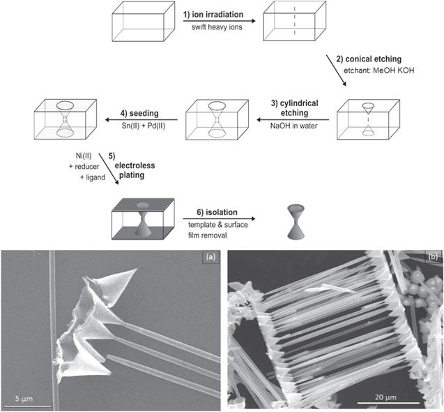
Figure 2. Fabrication scheme of funnel-shaped nanotubes based on ion-track etched polymer templates (a) SEM detail image of funnel openings obtained by Ni plating and template removal, (b) SEM survey image showing an array of parallel Ni funnels.
Download figure:
Standard image High-resolution imageFor successful track etching, it is necessary that the track etch rate vT exceeds that of the isotropic bulk etch rate vB. The track etch rate vT correlates with the linear energy transfer of the particle along the track and is higher on the ion entry side than on the exit side. The resulting pore geometry is influenced by the etch rate ratio vT/vB and can be adjusted according to it. While vT 》vB, then small etch rate ratios lead to produce conical pore geometries. External parameters such as the concentration and temperature of the etching solution, or any applied voltage, can cause conical pores via the etch rate ratio [42].
In this part a strong KOH bath containing methanol was used to produce conical pores on both sides of the polymer membrane. In the second etching step with aqueous NaOH, prior to the breakthrough of the conical pores, results in a double funnel structure, alternatively 'bow tie' or 'dumbbell' structure. Dissolved KOH is a stronger etchant than NaOH for polycarbonate at a given temperature and concentration [43]. By decreasing the interface energy and alcoholytic breakage of ester groups, methanol increases the bulk etching rate vB of the etching solution [44]. Given an initial nominal template thickness of 60 μm, the metal pore replicas are only 45.3 μm long, achieving an approximate KOH bulk etching rate vB of 12.9 μm min−1.
A distinct necking can be observed at the transition between cone and cylinder of the metal structures. The tube diameter decreases at the neck to about 0.3 μm. These tapered tube ends can also be observed in the other samples produced, as other research groups have observed in their samples [45, 46]. The reason for this morphology is suggested to be (1) an altered surface layer due to film manufacture [47], (2) the influence of a secondary electron cascade during track formation or (3) an amplifying effect of the etching products [46]. Since micrometers of our surface layer were removed in the initial methanol-KOH etchant, and, more importantly, the necking of the cylindrical pore section occurred in the interior of the template, below the conical pores, we can certainly exclude reasons (1) and (2), since an initial electron cascade as well as altered polymer surface properties cannot explain altered etching properties deep within the template membrane. Since analyses have suggested that etching products as well as surfactants reduce the etching rate [47], another mechanistic factor might be in play, but based on our observations, the origin of the necking cannot be surface related.
The base diameter Db of the cones is about 4.3 μm, at a length L of 5.1 μm. From this a track etching rate vT of 24.9 μm min−1 can be derived. The excess of vT over vB determines the cone.
If it is small, the angle becomes large [47]. With an assumed tip diameter d t of 0.1 μm, the calculated apex angle is 44.8°, in close agreement with the average measured angle of 45°. Apex angles of roughly 30° [48] and 40° [49] achieved with other methods. Other work on optimizing the cone angle has focused more on a smaller angle (<20°) and a sharp tip, aimed at using these structures as cold cathodes in field emission devices [50, 51].
The sides of the cone are not curved and run largely straight. Thus, it can be assumed that vT is approximately constant over time. A modification of this morphology could be achieved with a one-sided conical etching before cylindrical etching to produce metal structures consisting of a cylinder and only one cone [52].
3.2. Structural morphology influenced by deposition process
While previously we explored new pore shapes to realize new morphologies, here we want to show how ion-track templating can be combined with multiple deposition steps to create 1D core–shell nanostructures.
3.2.1. Wire-in-tube sample
In this part, electro- and electroless deposition techniques were applied to consecutively deposit metal nanowire trunks, which are then enclosed by nanotubes consisting of a different metal, i.e. a cylindrical core–shell structure. At the beginning, short Pt nanowires were electrodeposited in the cylindrical-pores of a polycarbonate membrane. Then, a second etching step was completed to enlarge the pore diameter, following by electroless Ni plating to obtain hybrid Pt–Ni 1D nanostructures.
Figure 3 shows the fabrication scheme of wire-in-tube samples and a SEM image of the segmented metal nanostructures. The length of the Pt wires is about 11 μm, at a diameter of about 240–300 nm. Then again, the surrounding Ni tubes have an outer diameter of 800–1000 nm and range across the entire template thickness. With a tube wall thickness of 60 nm, which can be further reduced over the deposition time, thin-walled tubes for special applications would also be possible. It is important to note that after the etching, the platinum wires might tilt and touch the pore walls, resulting in a non-connecting alignment, such as evident in figure 3 (hybrid wire-tube). Thus, is in accord with related synthetic approaches [53].
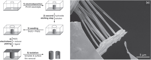
Figure 3. Fabrication scheme of wire-in-tube sample (left side) and SEM image of template-released core–shell nanostructures (a).
Download figure:
Standard image High-resolution imageThe fact that etching performs well around the nanowires tells us that the nanowires do not completely seal the pores, and that etching can efficiently encroach the sides of the wires and release the wires from the template, making space for a second deposition step. Pore widening might even occur in aggressive deposition solutions, resulting in an in situ modification of the template membrane, affecting the forming nanostructures in the process [38]. The annular gap between the wire and the pore wall remaining after the second etching provides space for a further nanocasting step.
The electroless Ni plating created tubes over the entire thickness of the template, which included the Pt wires, demonstrating our deposition concept. The major advantage of this approach is that the dimensions of the core and the shell can be adjusted independently of each other. The mixed tube-wire morphologies with etching between the depositions ('electrodeposition-etch-electrodeposition') was carried out by Loh et al [54] to synthesize coaxial hetero-nanostructures in which they show an increase of the tube thickness start from below point to upwards and more deposition takes place on the upper side of the wire, which does not lead to any further elongation of the tubular structures than the wire. Another point is the conductive contact in the solution, in which the deposition of the tubes does not occur from all walls at the same time. Compared to their study, we used a different deposition strategy (electrodeposition-etch-electroless deposition) and we achieved homogeneous thickness of tubes. It is important to note that our different deposition method leads to different mechanism in where deposition of the tube is coming from the walls and reaching into the center of the pore in order to complete a certain structure of completely embedded long tubes, wires of independently controllable length, which was not observed in the existing literature. Care are must be taken, where appropriate, to ensure that the materials deposited are in the correct order and that they are inert to the later employed reaction media. For instance, we chose to first deposit Pt and then Ni to prevent galvanic displacement between the metals, which would have occurred if the metal order was reverted. If this issue is considered, several films of different compositions can coat the core in a multilayer coaxial hetero structure. Multilevel nanostructures characterized by interior substructuring are interesting for devising tailored microreactor or sensor architectures [55], and ion-track etching provides a flexible route for rationally constructing such materials.
3.2.2. Tube-on-wires sample
Metallic bisegmented nanostructures composed of a Pt nanowire topped by a Ni nanotube cap were created in a similar fashion to the wire-in-tube nanostructures, but without the intermediate etching step. For demonstrating this approach, we started with Pt electrodeposition followed by Ni electroless plating to create one-sided Ni nanotubes partially filled with Pt. It is important to note that the Ni shell covers the Pt wire but in areas without Pt wire only the pure Ni shell remains.
The fabrication scheme and SEM images of the tube-on-wire sample are depicted in figure 4. The length of the Pt wires is about 2.2 μm, at a diameter of about 200 nm. Due to the missing etching step, the wires and tubes share the same diameter. The entire length of the pore is used to form the tube during electroless plating, but if electrodeposition is used, the tube length can be adjusted like the wire length via the deposition time. While in this work we focus on different metals and oxides, we want to note that electroless plating and electrodeposition represent versatile methods capable of depositing a range of metals in nanostructured form, as we have previously shown, e.g. in the fabrication of Au, Ag, Pt or Cu nanotubes [27, 36]. Also, other deposition reactions such as layer-by-layer method can be used to introduce different material classes into such nanostructures. Multi-segmented nanotubes and nanowires have been observed by Roy et al using polypyrene electrodeposition or layer-by-layer deposition to create organic nanotubes attached to the top of metal nanowires [7]. However, we are probably the first and show this deposition reaction with metals.

Figure 4. Fabrication scheme of tube-in-wire sample (left side) and SEM images of template-released tube-in-wire sample (a). The Pt wire is about 2.2 μm in length with subsequent broken Ni tube as second segment (b).
Download figure:
Standard image High-resolution imageTEM images including EDS measurements were recorded to verify the elemental composition of the nanotube-nanowire segments (figure 5). Which according to the synthesis scheme depicted in figure 4 should consist of nickel and platinum, respectively. Meeting expectations, mainly Pt can be found in the wire and Ni in the tube. Clear C and O signals stem from the resin, the Cu is assigned to the TEM grid. Embedded boron from the deposition solution can hardly be detected with this method. Pd contained in the tubes from catalytically active nuclei could not be verified because of its low quantity.
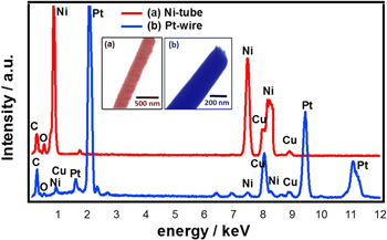
Figure 5. Elemental analysis and TEM images of the narrow-tube-on-wire sample (SEM images of this sample are depicted in figure 4). (a) Ni tube segment and (b) Pt wire segment.
Download figure:
Standard image High-resolution imageEmbedded in resin, it is extremely difficult to cut the nanostructure at a perfect angle in the longitudinal direction. As a consequence, areas corresponding to the nanowire and nanotube se nanotube sections of the hybrid 1D nanostructures were examined separately by EDS (figure 5).
Different synthesized samples were discussed by means of nickel and platinum structures using elelctro- and elelctroless deposition. By combining a template-assisted synthesis for metal nanotube arrays with the autocatalytic deposition of shape-controlled metal nanocrystals, the composition and morphology of the underlying material can be further altered. To illustrate the wide range of possibilities we have produced derivatives with Ni metals and oxide (TiO2). In this work, we focused on Ni deposition because of the good mechanical stability of the resulting nanostructures, facilitating the production of free-standing architectures enduring the template removal. But the approach is likewise applicable to different metals and even metal combinations.
3.2.3. Spiky Ni nanofunnels
In the previous sections, the pore geometries of the template were replicated with rather smooth metal wires or coatings, resulting in nanostructures closely matching the original pore shape. Here, we want to showcase how the shape-controlled deposition of anisotropic nanocrystals onto template-assisted 1D nanostructures allows constructing hierarchical architectures. The requirement for the nanospike deposition to smoothly proceed is that the substrate acts as a catalyst in the anodic oxidation of the employed reducer [56], so that electrons are generated on the nanostructures, which are channeled into the reduction of the surrounding nickel complexes, causing the nanospikes to start growing. In the first step, an already etched polycarbonate film was deposited with a thin nickel film using electroless nickel plating bath for a smooth nickel nanotubes production. Then a further specified nickel plating bath (see experimental part) resulted in the formation of funnelled nanotube arrays, over coated with a dense layer of nickel nanospikes. It is noted that the formed Ni nanotubes are already catalytically active and therefore do not require prior seeding. Figure 6 shows the fabrication scheme (left side) and SEM image (right side) of a spiky Ni-nanotube sample.

Figure 6. Fabrication scheme of a spiky Ni-nanotube sample (left side); SEM image of a spiky Ni deposition on Ni funnel nanostructures (b).
Download figure:
Standard image High-resolution imageOn top of the smooth nickel film, nickel spikes have grown on both sides of the structure from the specified deposition solution. Simultaneous etching of the membrane allows deposition also on the outside of the 1D nickel structures. This increases the surface-to-volume ratio while maintaining mechanical stability. Applications of nickel micro- and nanostructures, which depend on the surface size, can therefore benefit from decorating with spikes. Growing along twinning defects, they can be up to 150 nm long with a deposition time of 1 h [38]. When deposition takes more than twice as long, the spikes in our samples have grown up to 500 nm in length and are distributed homogeneously on the surface of the metal structures. Hydrazine, which acts as a reducing agent in the plating bath, also enhances pore widening during electroless deposition. Such a design is interesting to increase the surface area of an underlying architecture (e.g. for enhancing the amount of exposed interface for heterogeneous catalysis or sensing) [57, 58], to achieve bimetallic synergies, or to introduce novel functionalities.
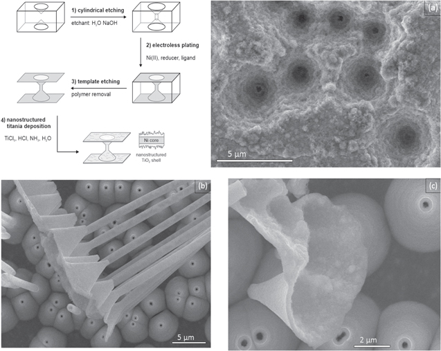
The multi-deposition strategy is not limited to metals, another class of materials can also be deposited on the 1D nickel structures, in this case oxides. To demonstrate this possibility, we combined the Ni nanofunnel arrays obtained by electroless plating with a consecutive chemical bath deposition to overcoat them with a nanostructured titania coating. A fabrication scheme of TiO2 deposition on Ni funnel nanotubes can be found in figure 7 (left upper side). First, conical etched polycarbonate film was coated with electroless Ni bath (step 1), then a chemical bath solution (step 2) contain Ti3+, which is continuously oxidized over time, resulting in a supersaturation of the solution with respect to Ti4+, resulting in the nucleation and growth of a TiO2 nanocrystal film [36]. Due to its mechanism, this deposition is less selective than the previously employed autocatalytic nanospike modification reaction, resulting in homogeneous nucleation in the bulk solution alongside the growth of a nanostructured coating on the metal nanostructures. Removing the template reveals the core–shell structure with a rough TiO2 inner surface due to low conductivity and a smooth Ni outer surface, which are easily discernible in SEM figures 7(a), (b).
Figure 7. Fabrication scheme of a Ni-TiO2 nanotube sample (left upper side); SEM images of the funnel-shaped Ni-TiO2 heterostructure, rough oxide layer inside the cone openings, poor conductivity of TiO2 overcoating (a). Side view of smooth outer Ni layer (b), top overview of outer Ni layer (c).
Download figure:
Standard image High-resolution image
Both layers consistently reproduce the pore geometry. Hetero-nanostructures composed of a metals and metal oxides can exhibit synergies and multifunctionality and are interesting e.g. to create fuel cell catalysts [40] or reusable photocatalysts [59].
4. Conclusions
We deem a full-scale implementation of our nanostructures out of the scope of the present work, which is focused on synthesis development and show casting new nanofabrication strategies. In this work, we described the template-assisted, fully wet-chemical synthesis of several new 1D nano-architecture types, whose increased structural and compositional complexity is achieved by a combination of post-etching membrane modification, intermediate and multiple etching steps, and consecutive deposition reactions: (i) metal nanotubes of elliptical cross-section were produced using porous track etched membranes where stretching is introduced as a way to form elliptical porous membranes. Elliptical pores in membranes, as we have created by stretching, can increase the flux while filtering more particles than round pores [60]. (ii) Synthetic guidelines for controlled conical pores are presented, which yield funnel-shaped nanotubes. This is an important approach to modify different pore shape for potential applications that produces larger apex angles than common methods. (iii) Metallization was performed using Pt electrodeposition and/or electroless Ni plating as our standard deposition methods, depending on the sample. As an example, for the variety of suitable deposition methods, we implemented spiky nickel deposition and chemical bath deposition of oxides in nanocasting either individually or in combination. Applied to polycarbonate films, we use combinations of etching and deposition methods to create tube-wire heterostructures, and core–shell structures. The demonstrated ability to create multi-component nanostructures comprising segmented and core–shell architectures allows investigating and exploiting functional advantages such as synergistic effects [33, 61] or the ability to protect a sensitive core material from oxidation [62].
Acknowledgments
We sincerely thank GSI (Helmholtz Centre for Heavy Ion Research) for access to the ion accelerator and the facilities for template preparation.
Data availability statement
All data that support the findings of this study are included within the article (and any supplementary files).