

Abstract
Flexible smart electronics require their energy storage device to be flexible in nature. Developing high-performance flexible energy storage devices require direct integration of electrode active materials on current collectors to satisfy the high electronic/ionic conductivity and long-term durability requirements. Herein, we develop a flexible all-solid-state asymmetric supercapacitor comprised of reduced graphene oxide (rGO) and core/shell tungsten trioxide/tungsten disulfide (WO3/WS2) nanowire based electrodes. The electrodes synthesized via electrochemical deposition and chemical vapor deposition avoided the necessity to use non-conductive binders and offered excellent cyclic stability. The structural integrity provided by the rGO and WO3/WS2 electrodes facilitated excellent electrochemical stability with capacitance retention of 90% and 100% after 10 000 charge-discharge cycles, respectively. An all-solid-state device provides a voltage window of 1.5 V and more than 70% capacitance retention after 10 000 charge-discharge cycles. Providing 97% capacitance retention upon mechanical bending reveals its potential to be used as an energy storage devices in flexible electronics.
Export citation and abstract BibTeX RIS
1. Introduction
Flexible energy storage devices have a vital role in powering next-generation multifunctional smart electronics and the internet of things [1, 2]. The fast-paced world requires energy storage devices powering these smart electronics to be fast charging and portable in nature. Supercapacitor or electrochemical capacitor is one such device that possesses advantages of rapid charge and discharge capability, high power density, long life span, safe operation at wide temperature range and environmental friendliness [3, 4]. The foremost challenge in developing flexible supercapacitors is developing flexible electrode materials which have good mechanical integrity with the substrate and can endure the hundreds of thousands of bending and folding cycles during its application [5, 6]. Two dimensional (2D) nanomaterials that can satisfy the aforementioned requirements garnered a lot of attention as an efficient energy storage material due to their ultra-thin nature of single to several atomic layer thickness offering flexibility and high mechanical integrity [7]. Also, the large overlapping areas formed via layer by layer assembly of 2D materials offers large surface area, more electroactive sites, and faster ion transport. Some of the best known 2D nanomaterials employed in supercapacitors are graphene, reduced graphene oxide, transition metal dichalcogenides (TMDs), MXenes, etc [8–10]. These 2D nanomaterials store energy via electrochemical double layer capacitance and/or pseudocapacitance mechanism. Graphene, a 2D nanomaterial for energy storage, has sp2 bonded carbon atoms in a 2D honeycomb lattice structure [11]. Graphene offers a high specific surface area, good electronic conductivity and excellent mechanical strength required for flexible supercapacitors [12]. Graphene oxide (GO) and reduced graphene oxide (rGO) nanosheets have been employed as an efficient electrode material in supercapacitors due to their electrochemical double layer capacitance (EDLC) charge storage mechanism offering good cycle life.
TMDs as an ideal supercapacitor electrode with the structure of MX2, (where M is W, Mo or X is S or Se) offers intrinsically layered structure, large surface area, variable oxidation states, and faster ionic transport [13]. Despite offering all these merits, the TMDs still suffer from poor cycle life due to the restacking of the nanolayers [14, 15]. The poor structural integrity can be resolved by developing composites, employing spacers, or developing hybrid core/shell nanostructures [16–18]. Among the TMDs, WS2 with 2D covalently bonded S–W–S layered structure offers a large surface area, making them one of the ideal energy storage material. The WS2 can store charge via intercalation mechanism as well as W atoms have a wide range of oxidation states varying from +2 to +6, making WS2 to be a promising pseudocapacitive material for energy storage applications [19].
Conventional supercapacitors use an insulating polymer binder, which hardly contributes towards capacitance and restricts the flexibility of the devices. To obtain the full benefits from the flexible supercapacitors, the best approach is to synthesize or deposit the electrodes as binder-free, free-standing films [20–23]. Chemical vapor deposition (CVD), hydrothermal deposition, electrochemical processes such as electrochemical deposition and electrophoretic deposition are some of the efficient approaches for developing binder-free electrodes with novel nanostructures which is scalable, relatively low cost and environmentally friendly [24–26]. We deposited both our electrodes directly on the current collector substrates following an electrochemical deposition process for the rGO electrode and CVD synthesis process for WO3/WS2 electrode.
Low energy density in supercapacitors can be improved by developing asymmetric supercapacitors (ASCs), wherein two different electrode materials working in different potential windows are assembled together [27]. Nevertheless, energy density also depends on the type of electrolyte used in the device. It has been observed that organic and ionic liquid electrolytes offer higher operating voltages (up to 4 V) due to high electrochemical stabilities, which in turn increases the energy density in supercapacitors [28, 29]. However, the high viscosity, lower ionic conductivity, toxicity, flammability, and expensive nature of these non-aqueous electrolytes makes them incompatible for next-generation flexible supercapacitors. Asymmetric supercapacitors in aqueous electrolytes show significant advantages even at higher operating voltages without any thermodynamic breakdown potential of water molecules, which is typical in symmetric supercapacitors operating beyond 1 V in aqueous electrolytes. Herein, we report the fabrication of an asymmetric supercapacitor using electrochemically deposited rGO anode on Nickel (Ni) foam and CVD deposited core/shell WO3/WS2 cathode, to tackle the issue of the structural integrity of electrodes in long-lasting flexible energy storage devices. The high-performing asymmetric cell with directly integrated electrodes offers less charge transfer resistance, more than 70% capacitance retention after 10 000 charge/discharge cycles and maintains 97% capacitance when subjected to mechanical bending.
2. Results and discussions
Raman spectra of GO and rGO on Ni foam is shown in figure 1(a). The presence of two strong vibration bands corresponding to in-plane stretching of sp2 bonded C–C atoms (G–band) and out-of-plane first order scattering due to the presence of structural defects (D–band) suggests the presence of GO and rGO. The D– and G–band for GO appears at 1359 cm−1 and 1598 cm−1 while they are down-shifted to 1356 cm−1 and 1587 cm−1 for rGO. It is observed that the intensity of the D to G band ratio (ID/IG) increases from 0.86 to 1.02 upon reduction of GO to rGO, which indicates restoration of the sp2 network and the removal of oxygen functionalities [30]. Thus the increase of the ID/IG ratio after reduction confirms the good reduction efficiency of lithium perchlorate (LiClO4). Further the X-ray diffraction (XRD) pattern recorded for the rGO electrode (figure 1(b)) displays the the existence of broad peak at 2θ value of 23.5°, which is a characteristic peak representing the reduced graphene oxide formed after the removal of the oxygen functionalities [31]. The Raman spectrum of the core/shell WO3/WS2 electrode is shown in figure 1(c). The spectra revealed the presence of both WO3 and WS2. The presence of the WO3 core was confirmed by a small peak at ∼700 cm−1, which arises from the stretching modes of O–W–O bonds [32]. The presence of Raman bands at 421.1 and 352.3 cm−1 corresponds to A1g and E12g vibration modes, respectively, which arises from W–S stretching in the WS2 outer shell [33]. The first and second-order Raman modes of WS2 shell were confirmed by the presence of additional peaks at 324.6 and 582.6 cm−1, respectively [34]. The XRD pattern recorded for the WO3/WS2 electrode shown in figure 1(d) reveals the presence of hexagonal WO3 core. The sharp characteristic diffraction peaks observed at 2θ values of 13.95°, 23.2°, 28.1°, 33.83°, 36.76° and 48.3° corresponds to (100), (002), (200), (112), (202) and (004) crystal planes arising from the hexagonal core respectively [35]. Also, a small sharp peak observed at 58.1° corresponding to (200) crystal plane represents the tungsten foil. Due to the small thickness of the WS2 shell, it is not revealed in the XRD pattern.
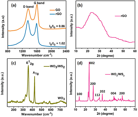
Figure 1. Raman spectra of (a) GO, rGO and (c) WO3/WS2 core/shell nanowires electrodes XRD of (b) rGO and (d) WO3/WS2 core/shell nanowires electrodes.
Download figure:
Standard image High-resolution imageFigure 2(a) shows the scanning electron microscopy (SEM) image of the pristine Ni foam prior to electrodeposition. The 3D interconnected porous structure of the Ni foam provides enormous surface area for conformal anchoring of the 2D rGO nanosheets, an easy pathway for ion-diffusion/charge transport, as well as increased access of electrolyte ions to the rGO nanosheets through pores. The deposition time of rGO was optimized to ensure an optimal loading of active material to avoid hindering the accessibility of the electrolyte ions in reaching rGO nanosheets through the Ni pores. Figure 2(b) shows the SEM image of the electrodeposited rGO nanosheets on the Ni foam, which clearly displays that rGO nanosheets are deposited on the edges of the Ni foam providing large surface area and preserving the porous structure which is vital for electrolyte infiltration and higher charge storage. The electrodeposited rGO on Ni foam has a wrinkled and layered structure (figure 2(c)). The wrinkled morphology with the large surface area along with the porous nature of the optimized electrode enhances the available electrochemical active sites, thus increasing the charge storage in the electrode. The transmission electron microscopy (TEM) image of the rGO nanosheets (figure 2(d)) isolated from the Ni foam via ultrasonication reveals that the lateral size of the 2D rGO nanosheets is about 20–30 nm and are very thin. The direct linkage of the thin rGO nanosheets to the Ni foam facilitates a longer cycle life. The SEM images of the WO3/WS2 electrode in figure 2(e) shows densely grown nanowires with each nanowire having a diameter of ∼150–200 nm and a length of ∼8–10 μm. The uniform and densely deposited nanowires offer an enormous surface area for charge storage. The WO3 core offers faster electron transport and the outer WS2 shell obtained after sulfurization of the nanowire facilitates faster ion transport and charge storage. A single nanowire isolated from the electrode revealed its uniform diameter when imaged under the bright-field (BF) TEM (figure 2(f)). The Annular Dark Field Scanning TEM (ADF-STEM) image (figure 2(g)) of the nanowire marked in red box (figure 2(f)) shows that the nanowire has atomically sharp interface distinguishing WO3 core and WS2 shell. The highly single-crystalline WO3 core's outer section is sulfurized into uniformly spaced WS2 shell. Such a self-assembled binder free electrode with strong core supporting the WS2 shell provides structural integrity for achieving a longer cycle life.
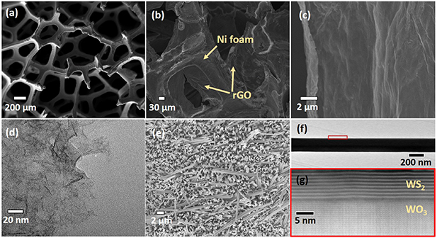
Figure 2. SEM images of (a) Ni foam (b) electrodeposited rGO on Ni foam (c) high magnification SEM image of rGO/Ni foam (d) TEM image of isolated rGO nanosheets (e) SEM image of densely aligned WO3/WS2 core/shell nanowires (f) low-magnification bright field TEM image of a single WO3/WS2 nanowire (g) high-angle annular dark-field scanning transmission electron microscopy (HAADF-STEM) image of the red box region in (f) showing WS2 layers covering the WO3 core.
Download figure:
Standard image High-resolution imageThe electrochemical performance of the rGO and WO3/WS2 nanowire electrodes was carried out in a three-electrode cell using aqueous 0.1 M Na2SO4 electrolyte. The CV curves of the rGO electrode were recorded in the potential range of −0.8 to 0 V vs SCE (saturated calomel electrode) at different scan rates, as shown in figure 3(a). The observed rectangular shape of the CV profile with good reversibility clearly indicates a good capacitive behavior of rGO, which is mainly attributed to the EDLC charge storage mechanism. The symmetrical CV profile without any oxidation and/or reduction peaks obtained from rGO is indicative of high rate capability, good mechanical stability, and small charge transfer resistance. The rGO electrode exhibited a maximum areal capacitance of 70 mF cm−2 at a scan rate of 5 mV s−1 as recorded from the CV curves. The GCD measurement of the rGO electrode displayed a linear and symmetrical triangular curve at various current densities ranging from 1 to 10 mA cm−2, further confirming an EDLC charge storage behavior (figure 3(b)). The rGO electrode displayed a good rate performance delivering an areal capacitance of 40 mF cm−2 at a high scan rate of 100 mV s−1. The gradual decrease in capacitance with increasing scan rate, as shown in figure S1 (available online at stacks.iop.org/NANO/31/435405/mmedia) is attributed to the increase of ion diffusion related resistance [36]. The cycle life of the rGO electrode evaluated at a scan rate of 100 mV s−1 exhibited 90% capacitance retention after 10 000 cycles (figure 3(c)), demonstrating the significant electrochemical stability of the electrode. The slight decline in electrode's performance during cycling is due to the minor detachment of rGO nanosheets from the Ni foam over repetitive shuttling of sodium ions, which will also increase the charge transfer resistance within the electrode. This was evident from the Nyquist plot recorded for the rGO electrode before and after cycling, as shown in figure 3(d). The Nyquist plot depicts that at the high-frequency region, the electrode maintains its equivalent series resistance value while the charge transfer resistance increases from 1.1 Ω to 3 Ω after electrochemical cycling. The good capacitive behavior of the electrode is evident from the nearly vertical line recorded in the low-frequency region [37].
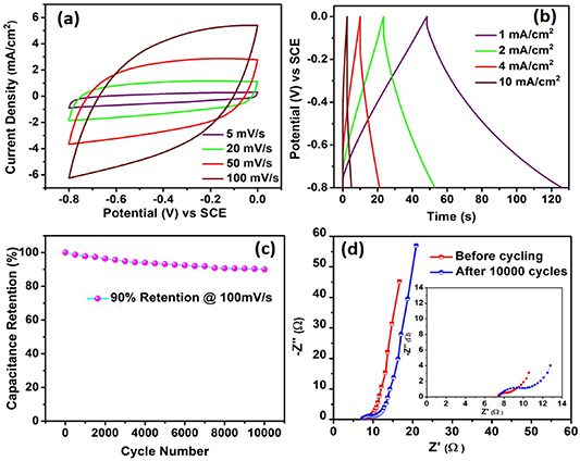
Figure 3. Electrochemical characterization of the rGO electrode (a) cyclic voltammetry (CV) curves recorded at different scan rates (b) galvanostatic charge-discharge (GCD) curves recorded at different current densities (c) cycle test of rGO electrode at 100 mV s−1 (d) Nyquist plot recorded before and after 10 000 electrochemical cycles. Inset in figure (d) shows magnified view of Nyquist plot.
Download figure:
Standard image High-resolution imageThe WO3/WS2 electrode tested in aqueous 0.1 M sodium sulfate (Na2SO4) electrolyte in the potential range of −0.3 to 0.5 V vs. SCE displayed a dominant EDLC behavior with a slight pseudocapacitive activity as shown in figure 4(a). A slight distortion observed in the symmetrical CV curves is due to the pseudocapacitance contribution arising from intercalated sodium ions in the WS2 shell. The GCD curves recorded from 0.5 to 5 mA cm−2 displayed a linear and symmetrical behavior (figure 4(b)). At a higher scan rate and current density, the electrode retained the symmetrical charge storage behavior displaying a good rate performance. A maximum areal capacitance of 55.3 mF cm−2 was recorded at 5 mV s−1, as seen in figure S2. The robust WO3 core helps in upholding the stability of the electrode structure during the electrochemical cycling at a higher scan rate. The well spaced WS2 shell accommodates the sodium ions without disrupting the available electrochemical active sites. These benefits offered by the electrode led to unprecedented cycling stability with more than 100% capacitance retention after 10 000 electrochemical cycles at 100 mV s−1 (figure 4(c)). A gradual increment is observed in the capacitance of the electrode until 2500 cycles due to the increase in the available electrochemical active sites as the interlayer spacing of the WS2 shell increases due to the strain caused by the intercalation and deintercalation of sodium ions [38]. Thus, the electrode was able to accommodate more ions leading to increased storage of energy. The Nyquist plot comparison of the pristine and cycled WO3/WS2 electrode shown in figure 4(d) depicts a considerable decrease in the value of the equivalent series resistance and the charge transfer resistance of the electrode that underwent 10 000 electrochemical cycles. This decrease in the overall resistance of the electrode can be correlated with the improvement in the capacitance value of the electrode obtained after cycling, which arises from the increased available electrochemical sites due to the enhanced interlayer spacing between the WS2 shell [39].

Figure 4. Electrochemical characterization of the WO3/WS2 electrode (a) CV curves recorded at different scan rates (b) GCD curves recorded at different current densities (c) cycle test of WO3/WS2 electrode at 100 mV s−1 (d) Nyquist plot recorded before and after 10 000 electrochemical cycles.
Download figure:
Standard image High-resolution imageThe good electrochemical performance delivered by the electrodes prompted us to construct an asymmetric supercapacitor. The asymmetric supercapacitor was built using rGO as anode and WO3/WS2 as the cathode in aqueous 0.1 M Na2SO4 electrolyte. Figure 5(a) shows the CV curves of rGO and WO3/WS2 electrodes with their optimal capacitance and stable voltage window of operation at a scan rate of 100 mV s−1. To ensure the stable operation of the asymmetric device, and to achieve maximum device capacitance, and longer cycle life, the charge balance between the cathode and anode should be maintained using the following relation,
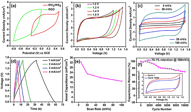
Figure 5. Electrochemical characterization of asymmetric supercapacitor in aqueous 0.1 M Na2SO4 electrolyte (a) CV curves of the rGO and WO3/WS2 electrode in a three-electrode system at a scan rate of 100 mV s−1 (b) CV curves of the rGO // WO3/WS2 cell measured at different voltages at a scan rate of 100 mV s−1 (c) CV curves of the asymmetric cell measured at different scan rates (d) GCD curves of the asymmetric cell measured at different current densities (e) plot of areal capacitance vs scan rate (f) cycle test of the asymmetric cell showing capacitance retention for 10 000 cycles. Inset inside (f) shows the CV curve comparison of 1st and 10 000th cycle.
Download figure:
Standard image High-resolution imagewhere q+ and q− denotes the charges stored on the cathode and anode, respectively. The signs C, ΔE and A denote the areal capacitance, potential window and active electrode area of the respective electrodes. As seen from three-electrode studies, the areal capacitance of the rGO and WO3/WS2 was different, hence the deposited area of the active materials was adjusted for charge balance. It is apparent from the three-electrode studies, that the rGO electrode works in the potential window from −0.8 to 0 V vs SCE, while the WO3/WS2 electrode works from −0.3 to 0.5 V vs SCE. This indicates that the asymmetric supercapacitor cell assembled using these two electrodes could reach up to a maximum working voltage of 1.3 V and beyond, depending on the overpotential. This enhancement in the voltage window will increase the energy density of the assembled device. The optimized rGO // WO3/WS2 asymmetric cell in aqueous electrolyte exhibits an ideal capacitive behavior with nearly symmetrical CV loops without any distortion till a voltage window up to 1.5 V at a scan rate of 100 mV s−1 (figure 5(b)), which is a sign of the stable electrochemical performance delivered by the asymmetric supercapacitor in an extended voltage window. The GCD curves corresponding to different operating voltages obtained at a current density of 1 mA cm−2 indicates that the device has good charge-discharge capability until 1.5 V (figure S3). Further electrochemical measurements for the asymmetric cell were done at 1.5 V. The asymmetric cell maintained its rectangular, symmetrical CV curves as it was scanned from 5 to 100 mV s−1 (figure 5(c)), inferring a good capacitive behavior and rate capability. Similarly, GCD curves acquired at different current densities shown in figure 5(d) displays nearly triangular-shaped curves with negligible internal voltage drops, indicating the fast conduction of ions and electrons. Even at a higher current density of 4 mA cm−2, the asymmetric cell retained a linear symmetrical profile indicating good rate performance and low internal resistance. The direct integration of both the electrodes to the current collectors helped in achieving faster electron transport, which was evident from the low charge transfer resistance observed in the asymmetric cell (figure S4). The maximum areal capacitance delivered by the rGO // WO3/WS2 asymmetric cell is 32.5 mF cm−2 at a scan rate of 5 mV s−1, and the cell retained more than 50% of the capacitance at a higher scan rate of 100 mV s−1 (figure 5(e)). The areal capacitance calculated from the GCD curves was also consistent with the CV results, offering a maximum capacitance of 31 mF cm−2 at a current density of 1 mA cm−2. The asymmetric cell exhibited a maximum areal energy density of 10.5 µWh cm−2 and a maximum areal power density of 1.4 mW cm−2, which is higher than some of the reported supercapacitors [40–43]. A Ragone plot comparing the performance of various supercapacitors with rGO // WO3/WS2 cell is given in figure S5. Longer cycle life is desired from the asymmetric supercapacitors for practical applications. The cyclic stability of rGO // WO3/WS2 cell was evaluated at 1.3 V and 1.5 V at a scan rate of 100 mV s−1, as shown in figures S6 and 5(f). The full cell exhibits excellent capacitance retention of 87.2% (at 1.3 V) and 70.1% (at 1.5 V) after 10 000 charge-discharge cycles. Cyclic stability comparison of some ASCs frabricated with carbon based anode and core/shell cathode electrode materials with our device is provided in table S1. It can be seen that the direct integration of electrodes onto current collectors is important for achieving a longer cycle life. The possible reason for an additional decrease in the capacitance retention when cycled at 1.5 V would be the overpotential affecting Nickel foam's strength, thus causing the rGO to detach from the electrode upon multiple times of insertion and removal of Na+ ions [44].
To demonstrate the flexibility of our device, an asymmetric solid-state supercapacitor (ASSC) was fabricated by sandwiching the the two electrodes (rGO and WO3/WS2) with PVA–Na2SO4 gel electrolyte. Figure 6(a) shows the CV profiles of the flexible rGO // WO3/WS2 solid-state device at different scan rates from 5 to 100 mV s−1. The typical rectangular CV curves without any shape change at all scan rates confirms a good capacitive behavior in a solid-state device. The maximum areal capacitance obtained from the flexible ASSC device was 20 mF cm−2 at 5 mV s−1, suggesting the efficient penetration of the gel electrolyte into the porous networks of the electrodes on either side. A comparatively low value of areal capacitance observed in solid-state devices as compared to the asymmetric cell in liquid electrolytes could be attributed to higher internal resistance and slower electrolyte diffusion typically observed in solid electrolytes [45]. Figure 6(b) shows the GCD curves for flexible ASSC device at different current densities (0.25–3 mA cm−2). The GCD curves are nearly linear and symmetrical, proving a good capacitive behavior and agree with the CV results. To further evaluate the quality of the ASSCs for powering flexible electronics, the ASSC was subjected to mechanical bending tests at different bending angles form 0º to 90º. The CV curves recorded at various bending angles revealed a negligible change in capacitive performance (figure 6(c)), which indicates the high mechanical stability of the active electrode materials with the current collector. The ASSC maintained ∼97% of its capacitance up to a bending angle of 90°, as shown in figure 6(d). This higher capacitance retention shows that the direct integration of the electrode materials accommodate the strain caused during the bending and store the charges efficiently. To demonstrate the commercial viability of these ASSCs, two devices were connected in series to deliver a maximum voltage up to 3 V (figure S7). The two ASSCs connected in series maintained a good charge discharge behavior and were able to power up a red-light emitting diodes (LEDs) (figure S8).

Figure 6. Electrochemical characterization of ASSC (a) CV curves recorded at different scan rates (b) GCD curves recorded at different current densities (c) CV curves of ASC at different bending angles at 100 mV s−1 (d) plot of capacitance retention vs bending angle.
Download figure:
Standard image High-resolution image
3. Conclusions
An flexible all solid-state asymmetric supercapacitor was developed by direct integration of electrode active materials such as rGO and WO3/WS2 on to current collector electrodes. The individual performance of the electrode materials showed more than 55 mF cm−2 areal capacitance offered by the electrodes. The structural intergrity offered by the electrodes helped in achieving cyclic stability of 90% in rGO electrode and 100% in WO3/WS2 electrode after 10 000 electrochemical cycles. The asymmetric full cell built using 0.1 M Na2SO4 offered up to 1.5 V with more than 70% capacitance retention after 10 000 electrochemical cycles. A solid-state device developed in PVA/ Na2SO4 gel electrolyte showed its flexible nature and good mechanical behavior retaining more than 97% of its capacitance at a bending angle of 90°. Two of these devices connected in series were able to light up an LED.
Acknowledgment
J T acknowledges National Science Foundation (CAREER: ECCS-1351757 supplement) for the financial support.