


Abstract
In this paper, we propose a novel structure of a photonic two-dimensional force perceptron based on fiber Bragg gratings for the first time to demonstrate microforce detection and direction recognition in an all-optical transmission sensing platform. Silicone gel was used to encapsulate the Bragg gratings arranged in equilateral triangles with specific side lengths in a hollow cylindrical structure. The force stimulation is sensed by stress transfer ball located on top of the perceptron, and the force is transmitted to three Bragg gratings arranged in equilateral triangles through the encapsulation material. The perceptron can achieve force detection with a sensitivity of 
 and a force stimulation resolution of
 . The reset operation mainly relies on the high elastic modulus of the material itself. The results demonstrate continuous optical sensing of microforce stimulation ranging from
 to
to 
 , In addition, we presented the results of large-scale directional force stimulus recognition, successfully achieving directional recognition of force stimuli. Furthermore, we achieved angle recognition with an error rate of
  , prove the practical potential of constructing a precise positioning continuous all-optical force sensing platform.
Export citation and abstract BibTeX RIS
1. Introduction
Force sensing and perception have found wide applications in various fields such as industry, healthcare, environmental protection, and aviation. Currently, the mainstream method for measuring the flow velocity of liquids or gases in pipelines or air is by sensing the external forces experienced by the sensors and converting them into flow velocity through calculations. This data can be used for monitoring flow rates, measuring flow velocities, controlling flow rates, as well as predicting and preventing disasters. For example, in the medical field, flow sensors can be used to measure blood flow velocity inside the human body to aid in disease diagnosis and monitoring patient health. In the environmental field, flow sensors can be used to monitor flow velocity and water quality in sewage and wastewater to protect the environment and public health. Flow sensors are also used for measuring wind speed and direction, which are important in aviation and weather forecasting [1]. Due to the lack of sensing technology suitable for high-precision force stimulus perception and recognition in various complex environments, fiber optic sensors, which have excellent performance in measuring temperature, pressure, strain, flow rate, and other data in corrosive fluid environments, have received great attention [2–7]. Peng et al provided a summary of various fiber optic sensors that have emerged [8]. Currently, the sensors mainly include fiber optic flow sensors based on vortex shedding, laser Doppler velocimeters, and fiber flow sensors based on interference measurement techniques, where the modulation of low-coherence or speckle spectra is used for flow detection. With the robust performance exhibited by all-optical sensors in sensing and measurement, fiber optic sensors utilizing fiber Bragg gratings (FBGs) have witnessed rapid development.
In recent years, various explorations have been made to develop force sensors tailored to different working environments. In the field of fluid force sensing, some sensors utilize hot wire anemometry Pandya et al [9]. These sensors employ thermally dependent resistors in the form of nanowires placed in the flowing fluid, where the flow of the fluid cools the suspended nanowires, allowing for the measurement of fluid flow velocity. Most of these artificial sensors fundamentally rely on the strain induced by the deflection plate or cantilever structure at the bottom to respond to fluid flow [10]. This design avoids some unnecessary boundary layer effects [11]. However, sensors designed based on electrical strain rely on electrical signals and have limitations in operating environments. When operating in humid environments, the electrical signals can be affected by long-distance noise pickup, thereby impacting remote control and large-scale sensor integration.
Sensors based on FBGs not only possess characteristics such as wavelength encoding response, high sensitivity, and large dynamic range, but also offer advantages such as real-time optical communication, compatibility with fiber optic networks, and the ability for wavelength division multiplexing (WDM) and time division multiplexing. Lim et al developed an optical differential pressure flow sensor based on FBGs for monitoring and feedback control of opto-hydraulic valves [12]. Currently, the most effective structure for detecting fluid using FBG-based sensing systems is the cantilever beam structure, and extensive research has been conducted on such sensing systems. Lu and Chen proposed a novel fiber optic sensor system composed of cantilever beam-based FBGs as transducers for achieving fluid flow velocity and direction measurements in 1D [13]. With the emergence of new types of FBGs based on multi-core FBGs and multi-grating zone FBGs, there has been a growing exploration of multidimensional mechanical sensing using these FBGs. However, the limitation of sensors that can sense the direction of multi-dimensional mN force stimuli at the same time and limitation of such structures is their inability to be employed for sensing fluid forces [14–16]. Furthermore, FBG-based sensing systems utilizing cantilever beam structures for 2D fluid flow velocity detection have also been reported [11]. FBG sensors have also played an important role in gas sensing applications. For example, thermal x-probes composed of two cross-installed FBGs have been used to measure gas flow based on convective heat transfer principles [17, 18].
FBGs are produced by exposure to intense ultraviolet light permanently increases the refractive index of the fiber core, resulting in a fixed refractive index modulation according to the exposure pattern. The reflected wavelength of the Bragg grating changes as the grating pitch is compressed or stretched, and this characteristic allows the variation in wavelength to be correlated to the strain experienced by the grating region. Thus, an internal functional relationship can be established between the wavelength change and the applied strain on the FBGs. Regarding the measurement of strain and force using combined FBGs, a major focus has been on the overall curvature of the fiber structure. The study of the curvature at the end of the cylindrical structure using multiple bonded optical fibers with different geometric shapes was conducted by Araujo et al in 2002 [19]. In this case, the gratings need to be located on the outer side of the neutral axis of the cantilever beam structure. Similarly, extensive research has been conducted on cantilever-based FBG flow sensing systems for monitoring steady flow and flow disturbances [11, 13], but they lack two-dimensional directional recognition. To overcome these limitations, a FBG force perceptron based on a cantilever beam structure has been designed to achieve two-dimensional force sensing measurements. This perceptron simplifies the internal structure while enhancing large-scale directional force recognition and further improving angle recognition results.
Our proposed full-photon two-dimensional force sensor in figure 1 is suitable for force measurements in various environments. Forces ranging from 
 to
to 
 were applied to the force sensor to further verify its sensing performance. The sensor's response to external forces was reconstructed to determine the major direction of force. To ensure the practicality of the sensor, a strong strain isolator was added externally to block interference and protect the sensor from damage under strong external force. We believe that the full-photon two-dimensional force sensor demonstrates great potential for sensing platforms and can serve as an experimental basis and operational experience for all-fiber environmental sensing systems.

Figure 1. Illustrates the working principle of the full-photon two-dimensional force perceptron based on fiber Bragg gratings.
Download figure:
Standard image High-resolution imageThe force stimulus is received at the top of the perceptron and converted by the Bragg grating into wavelength shift, which is then transmitted through the optical fiber. Finally, the wavelength shift is converted into data by an optical interrogator. With variations in the magnitude of the mechanical force, the spacing between the gratings inside the sensor changes, resulting in a wavelength shift that is detected by the optical demodulator. In the absence of any force stimulus, the reset operation is achieved through the self-recovery of the rigid encapsulation material.
2. Perceptron design theory
2.1. Structure design
The main component of this force perceptron consists of a cylinder with three embedded FBGs and a sphere located at the top of the cylinder. Additionally, an open-cone-shaped strong strain isolator is included. To simulate the signal generated by the strain applied to the perceptron, we simplify the entire perceptron to a cantilever beam loaded with a weight at the top. The cantilever beam has a length of h, a circular cross-section, and a bending stiffness of  (where
  is the Young's modulus and
  is the second moment of area) is calculated based on the Bernoulli beam equation.
2.2. FBG sensing characteristics
The reflection wavelength of a FBGs primarily changes with the grating spacing  , and temperature and strain are the fundamental factors determining the variation. The thermal effect, which varies with temperature, is effective for basic FBGs Flockhart et al [20]. A differential strain configuration can be employed to compensate for the thermal effect, ensuring that the reflection wavelength
  of the FBG depends solely on the strain magnitude
  . The relationship between strain and reflection wavelength is given by equation (1)
2.3. Determination of strain magnitude and direction in the perceptron
For determining the strain magnitude and direction of the neutral plane, we first express the wavelength shift as signal strength  ,
,  ,
,  . Three standard deviations
  ,
,  ,
,  are defined as the difference between the received signal strength and the mean signal strength
The total strain magnitude is calculated using the Pythagorean theorem. We square each component, add them together, and then take the square root of the sum. This is equivalent to finding the length of a vector representing strain in three-dimensional space, where each component corresponds to a dimension. When Bragg grating wavelength is  , The amplitude of the strain received by the column is given by:
The direction of strain is determined by the relative intensities of the signals received from the three fiber channels. In this case, we can use an improved algorithm to calculate the direction based on the wavelength shifts with positive and negative intensity signals. Figure 2(b) illustrates the partitioning of the direction of stimulation. After receiving an external stimulus, we can classify it to any partition based on the different signal intensities from the three FBGs. Angle recognition calculations for force directions involve taking the wavelength shifts generated by the three FBGs and projecting them onto the xy-plane established in figure 3(a). The wavelength shifts are projected separately in the  -directions, thus we can get:
 ![$y = - [\Delta {\lambda _1} - (\Delta {\lambda _2} + \Delta {\lambda _3})\cos {60^\circ }]$](https://content.cld.iop.org/journals/0957-0233/35/4/046001/revision2/mstad157bieqn28.gif) ,
,  . By utilizing the differences in wavelength along the
  -directions, the angle values can be reconstructed using the arctangent function. It is important to note that the goal is to achieve 360° angle recognition, which is typically computed using the
  function borrowed from computer programming languages

Figure 2. (a) and (c) Schematic diagram of the perceptron structure design, sensing principle, and internal construction. (b) Sensing area for two-dimensional directional recognition. (d) When the perceptron receives external stimuli, the changes in the spacing of the FBG1, FBG2, and FBG3 grating regions result in wavelength peak shifts.
Download figure:
Standard image High-resolution image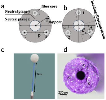
Figure 3. The cross section of a fiber supporting structure. (a) The cross section is depicted by a schematic diagram of a variable bending crankshaft with an angle of  relative to a regular triangular fiber lattice with a side length of
  . (b) Indicate the direction of bending and the resulting strain projection. (c) The all-optical continuous two-dimensional force perceptron has a height of
 and spherical body radius of
 . (d) A microscopical picture of the cross section of the perceptron tip in figure (a). Three fibers are embedded in the adhesive matrix.
Download figure:
Standard image High-resolution image2.4. The mechanical mechanism of the perceptron structure
To further investigate the magnitude of the forces that cause strain, this columnar structure can be equivalent to a cantilever beam. The mechanical characteristics of the cantilever beam Benham et al [21] are characterized by equations (7) and (8), where the strain at the cantilever height of  , the neutral axis bending distance of
  show in figure 3(b), and the cantilever top displacement of
  after receiving the force
  at the top of the cantilever are determined together. Among them, when the force magnitude is fixed,
  mainly depends on the cantilever height and the material's flexural rigidity
The cylindrical part of the strain sensor is equipped with three Bragg gratings arranged in an equilateral triangle pattern show in figure 2. The silica outer layer of the optical fiber is not removed. In order to achieve compatibility and integration with multi-level strain sensing in the future, the Bragg grating wavelength is mainly selected within the range of 
 in the communication band.
The bending stiffness  plays a crucial role in the mechanical performance of the fiber-supported structure of the strain sensor and is a key parameter affecting its sensing performance. It particularly depends on the elastic properties of the support cross-section and fibers and is strongly influenced by their geometry and composition. The composite structure of the support matrix and fibers implies that the bending stiffness
  is a function of the mechanical properties of both materials and is influenced by their relative proportions and arrangement. Additionally, the bending stiffness of each individual fiber depends on its distance to the neutral bending axis, which is defined as the axis around which the fiber can rotate without any additional bending. Importantly, the bending axis is not fixed and can rotate as the sensor is deflected in different directions. However, we have shown that the key mechanical parameter of the fiber-supported structure, the bending stiffness
  , does not need to be related to the variable bending axis offset
  .
.
When the strain sensor receives a strain force impact, and the sensor body is deflected by an angle  relative to its initial state, the relative positions of the three fibers in the
  direction change show in figure 3(b). We characterize the strain generated by the fibers themselves when the strain sensor receives an impact by the perpendicular distance
  ,
,  ,
,  and
and  ,
,  ,
,  between the fibers and the bending axis show in figure 3(b). The overall structure of the cylinder has no preferred bending direction and is mechanically isotropic in bending stiffness
  . Therefore, we can determine a direction-independent or isotropic bending stiffness at the top of the cylinder structure.

where  and
and  denote the cladding and support radii and
  and
and  their respective Young's moduli,
  represents the distance between the fiber cores.
Next, we provide the relationship between the main body deflection angle and the top displacement  of the cylinder when it receives an impact, as well as the differential strain vector of the fiber. We define the fiber spacing in the
  direction after the bending axis of the cylinder is offset by angle
  as follows:
The fiber spacing in the  direction is:
According to equation (8), we can obtain the differential strain in the  direction as follows:
With
The size of the absolute strain difference is calculated using polar coordinates, and we can obtain the size  and angle
  of the differential strain
Similarly, the wavelength shift difference can be used to obtain the wavelength difference in the  direction, and the relationship between the wavelength drift difference
  and the deflection
  is given by:


For the overall force applied to the cylindrical body, we have the relationship is as follows:
3. Experimental measurements and results
3.1. Experimental details
The processing and fabrication of the main body of the force perceptron involve critical factors such as the spacing between the fiber cores, the fixed position of the grating region, the length of the column, and the size and material of the stimulus-receiving sphere. The optimal dynamic range of the sensor is achieved with a spacing of 
 between the fiber cores and a distance of
 from the grating region to the bottom of the cantilever Wolf et al [11]. To approach the optimal solution, we fabricated the column as shown in figure 3(a), with a length of
 and a fiber core spacing of
 . To enhance the sensitivity of the sensor, we focused on the structural design of the column. For this purpose, we made the column hollow, as reducing its flexural stiffness can increase the sensitivity of the sensor, as shown in equation (7). Another important consideration is the necessity of the stimulus-receiving sphere at the top. The spherical shape of the stimulus receiver ensures the consistency of stimulus transmission to the grating, as it eliminates any preferred direction of stimulus perception. The diameter and material of the spherical stimulus receiver are determined based on the main objective of the mechanical sensor design, which is to enable perception of various complex force stimulus. To amplify the perception threshold of the sensor for force stimuli in different complex fluids, we can control the boundary thickness and diameter of the stimulus-receiving sphere to amplify the stimulus. To test the perception threshold of the sensor itself, we set the sphere diameter to
 , and the column material is made of silicone gel (SI587,LOCTITE, Germany) (van Netten & MacKinnon, 2013) [22].
Three SMF-28 optical fibers, with the jacket removed and a core radius ( ) of
) of 
 and Young's modulus of
 , were arranged in a precise equilateral triangle configuration. The positioning of the fiber cores was carefully controlled to ensure a maximum deviation of
 from the grating region to the fixed point of the cantilever. These fibers were encapsulated in the selected material for the column structure. To achieve this, we designed a specialized processing apparatus that enabled precise fiber fixation, installation, and column formation. The cross-section of the fabricated column is shown in figure 3. The base of the sensor was created using 3D printing and included a specific mounting component. The column was partially inserted into the mounting component and secured with adhesive, serving as the fixed cantilever point of the sensor. Additionally, a shielding cover was added to the external part of the sensor to effectively shield stray stimuli. Moreover, it prevented damage to the sensor in the event of excessive stimulation when reaching the sensing limit.
The mechanical sensor testing procedure is illustrated in figure 4. A precision microbalance (ESE, ES1035A, D&T, China) with a design accuracy of 
 was used to precisely control the applied force stimulus on the sensing sphere. The wavelength shift of the FBG was recorded using an optical demodulator (BJTW, TV-1600, TONG WEI SENSING, China) with a resolution of
 . The applied force on the sensing sphere was adjusted by controlling the linear stage's (WN28VM, WN28VM25M, Winner Optical Instruments, China) movement distance. The microbalance was used to display the magnitude of the applied force, allowing for precise control of force stimulus of any desired magnitude to be conveyed to the sensing sphere.

Figure 4. Setup of the experimental platform and related equipment.
Download figure:
Standard image High-resolution image3.2. Sensing characteristics of perceptron
We used a linear stage and a precision balance to control and measure the force applied to the receiving sphere. First, we examined whether the dynamic response of the sensor under fixed deflection force was consistent. It was essential to ensure that the three FBGs in the sensor were mechanically symmetric and had no preferred bending direction. This was crucial for determining the independent or isotropic bending stiffness  of the column in any direction. Figure 5 illustrates the wavelength shift of the column when subjected to a positive force stimulus. We used the linear stage to apply a fixed force stimulus to the column incrementally by a value of
 , ranging from
 to
to 
 . We measured the wavelength shifts of fiber core1, fiber core2, and fiber core3. The experimental results showed that the sensor was capable of detecting forces as low as
 , with a resolution of
 . Figure 6(a) demonstrates that the overall wavelength shift of fiber core1, fiber core2, and fiber core3 reached
 when the force ranged from
 to
to 
 . Under the increment of
 , the wavelength shifts of fiber core1, fiber core2, and fiber core3 were in the range of
 to
to 
 , proving that the force resolution of the sensor reached
 . Furthermore, in figure 6(a), it can be observed that when the initial stimulus increased from
 to
to 
 , the wavelength shift was
 . As the force stimulus continued to increase to
 and received an additional
 stimulus, the wavelength shift of the sensor remained stable at
 to
to 
 .Therefore, when the same incremental force stimulus was added to the sensor under different states, the dynamic characteristics of the sensor remained stable. However, when the applied stimulus approached the bending limit of the FBG, the column material's deformation started to affect the sensitivity of the sensor. Thus, in figure 6(b), we continued to increase the mechanical stimulus while ensuring that the FBG did not reach its bending limit. Based on a baseline of
 , we incrementally added a force stimulus of
 . The total increase of force stimulation was from
 to
to 
 .The experimental results in figure 6(b) showed that as the force stimulus steadily increased, the wavelength shifts of FBG1, FBG2, and FBG3 exhibited unstable increments, ranging from
 to
to 
 for each
 increment. As the force stimulus approached the bending limit of the internal grating in the sensor, the reflection peaks of the FBG also became unstab [23].When the sensor is subjected to forces nearby
 , the wavelength shift per
 increment starts to decrease noticeably. This suggests that as the applied force linearly increases, the wavelength shift provided by the linear within its sensing threshold, Ensure the consistency of the force perception output signal in the inner gate area of the sensor, and support the accuracy of perception direction.

Figure 5. Positive wavelength shift under forward force.
Download figure:
Standard image High-resolution image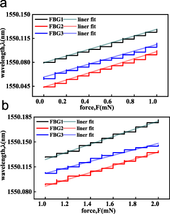
Figure 6. (a) The wavelength changes of three FBG were tested by increasing 
 force each time from
 to
to 
 FBG. (b) The total increase of force stimulation was from
 to
to 
 , and each increase of force stimulation was the wavelength shift of three FBG under the experimental condition of
 .
.
Download figure:
Standard image High-resolution image3.3. Directional recognition of the perceptron
Next, we further validated the directional recognition capability of the all-optical two-dimensional sensor. To achieve directional recognition in a two-dimensional space, it is necessary to have contrasting differences in both horizontal and vertical directions. Therefore, we designed the directional recognition based on the centroid of the equilateral triangle formed by the three FBGs, establishing the Cartesian coordinate system shown in figure 3(a). The two-dimensional plane is divided into three major directions as shown in figure 2(b): region 1 represented by FBG1, region 2 represented by FBG2, and region 3 represented by FBG3. The goal was to identify which region the stimulus came from when the receiving sphere received stimulus from any direction, enabling directional recognition.
To test the effectiveness of directional recognition for microforce stimulus, we used a step rotation stage to rotate the sensor at angles of  ,
,  and
and  , while applying fixed force deviations of
 to
to 
 at the top of the sensor. The important reason for choosing these three angles is that the current ideal direction recognition target is the general direction recognition of three regions, and the stimulus under these three angles can cover the direction perception of the whole two-dimensional plane. Next recorded the wavelength shifts of FBG1, FBG2, and FBG3 under the same force deviation in the three directions, as shown in figure 7. In table 1, we have presented the wavelength shifts of FBG1, FBG2, and FBG3 under three different force angles. When conducting large-area recognition, one can directly determine the source of the force direction (i.e. which quadrant it belongs to) by examining the signs of the three FBG signals. The quadrant associated with the positive signal corresponds to the direction of the applied force.

Figure 7. (a) Signal variations of FBGs under force stimuli starting at an angle of  with a force increment of
 , increasing up to
 . (b),(c) Signal variations under the same force stimulus conditions but with stimulus angles of
  and
and  , respectively.
Download figure:
Standard image High-resolution image
Table 1. Wavelength shift and recognized angle results of the sensor under specific angle stimulus.
| Force angle/area | Wavelength shift (nm) | Identify angle/area | |||
|---|---|---|---|---|---|
| FBG1 | FBG2 | FBG3 | |||
| −90°/area 1 | Test1 | 0.05 | −0.042 | −0.04 | −91.08°/area 1 |
| Test2 | 0.05 | −0.042 | −0.04 | −91.08°/area 1 | |
| Test3 | 0.05 | −0.043 | −0.04 | −91.07°/area 1 | |
| 30°/area 2 | Test1 | −0.036 | 0.045 | −0.036 | 30.17°/area 2 |
| Test2 | −0.036 | 0.044 | −0.036 | 30.17°/area 2 | |
| Test3 | −0.036 | 0.045 | −0.036 | 30.17°/area 2 | |
| 150°/area 3 | Test1 | −0.035 | −0.04 | 0.052 | 152.6°/area 3 |
| Test2 | −0.036 | −0.039 | 0.052 | 152.03°/area 3 | |
| Test3 | −0.035 | −0.04 | 0.052 | 152.6°/area 3 | |
For further angle recognition, the received signals can be input into equation (6) for calculation. Table 1 also demonstrates the experimental results of three repeated tests at each angle. The results indicate that under the same force stimulus, the sensor maintains stability in recognizing the force stimulus. The maximum error angle in the experimental results is 2.6° . We standardize the error angle, which is defined as error rate=|Identify angle-Force angle|/360°, and the error rate is less than 1%. The source of the perceptual error of the perceptron is mainly due to the inconsistency in the production of the fiber Bragg grating, and there will be a certain difference in wavelength offset when receiving the same force stimulus, and at the same time, in the actual production, the fiber Bragg grating arrangement can not be arranged in a perfect regular triangle, resulting in a difference between the force stimulus and the applied force stimulation angle when the force stimulus is transmitted to the internal fiber Bragg grating. In order to reduce the error, we can choose the fiber Bragg grating with better consistency and ensure that the fiber is arranged in a perfect triangle as much as possible.
The results demonstrate that, despite these challenges, the system achieves a relatively low angle recognition error of  with an error rate of
  , indicating its effectiveness in recognizing force directions and angles. As a result, we achieved directional recognition of force stimulus within the entire two-dimensional plane.
4. Discussion and conclusion
In this study, we demonstrated the use of Bragg gratings to construct a fully photonic continuous two-dimensional force sensing device with specific structures. The sensing threshold was as low as 
 . Through experimental and theoretical exploration, we further investigated the characteristics of the force sensor. A single sensor achieved a force resolution of
 and successfully achieving directional recognition of force stimuli. However, for precise angle recognition, there was a limitation of
  due to fabrication processes and variations in Bragg gratings. The advantage of designing a replaceable stimulus-receiving sphere at the top is that the sensor can adapt to force testing in different fluid environments, and it can be further applied to measure various fluid flow velocities. To adapt to complex testing environments, a shielding cover was designed outside the sensor to effectively suppress stray stimuli. Additionally, it could prevent damage to the sensor when the stimuli reached the sensing limit.
This study is only the first step towards a large-scale two-dimensional sensing and positioning platform. Two-dimensional force sensors have great potential in future sensing and positioning research. The proposed force sensing can achieve ultra-low micro-force detection and can be further expanded to multi-level sensing by changing the diameter of the column. The fully photonic system can be combined with existing and rapidly developing optical fiber networks, offering advantages such as fast response time and long-distance transmission. By using Bragg gratings with different reflective wavelengths, it is possible to integrate them with WDM systems, opening up broader application prospects. However, there are still areas for improvement, such as achieving more accurate angle recognition, using superior coating materials, and addressing dispersion issues in long-distance fiber transmission.
In this paper, we designed a new hollow cylinder structure and studied the all-optical continuous two-dimensional force perceptron. The new structure of three single-point FBGs embedded in the hollow cylinder not only enables the sensor to perceive micro-force stimuli, but also makes the wavelength offset produced by the internal FBGs larger. Increased sensitivity of the perceptron,compared with the existing micro force sensors which can perceive multi-dimensional force stimuli, the sensing sensitivity has been further improved [24–30]. At the same time, under the minimum requirement of direction perception in the two-dimensional plane: two groups of control points, the general direction recognition in the two-dimensional plane is realized by three single-point FBGs, and further shows the results of angle recognition. Bragg grating-based all-optical continuous two-dimensional force perceptron shows the characteristics of low cost, low manufacturing difficulty, high practicability and so on.
The manufacturing characteristic of adjustable force stimulus perception threshold makes clear the potential of all-optical continuous two-dimensional force perceptron application in fluid force perception engineering in complex environment. Based on the ability of all-optical continuous two-dimensional force perceptron generous direction recognition and further angle recognition, it also provides a substantial basis for the realization of large-scale all-optical continuous two-dimensional force stimulation location in fluid. Bragg grating-based all-optical continuous two-dimensional force perceptron article also shows that the maturity of the application of single point FBG makes it possible for all-optical continuous two-dimensional force perceptron to be immediately used in detection engineering.
Acknowledgments
National Natural Science Foundation of China (52271344); Natural Science Foundation of Heilongjiang Province of China (LH2021E032, LH2021F020)
Data availability statement
All data that support the findings of this study are included within the article (and any supplementary files).