
Vibration of compliant robotic grippers and wrists
Published December 2021
•
Copyright © IOP Publishing Ltd 2021
Pages 11-1 to 11-74
You need an eReader or compatible software to experience the benefits of the ePub3 file format.
Download complete PDF book, the ePub book or the Kindle book

Permissions
Abstract
Chapter 11 addresses vibration of compliant robotic grippers and wrists. The chapter includes modelling of vibration of CRG & CRW ab initio, for both in situ as well as external excitation. The author also discusses the local effects of vibration in this section, which are in the form of vibration accumulation at CRW and the consequences of external forcing on the robotic manipulator. Case-studies supported by test results are reported for a table-top small-sized semi-flexible robotic system, augmented with a tailor-made CRG.
Parts of this chapter have been adapted from [1] with permission from Springer.
11.1. Introduction
Industrial robotic systems have two essential functional sub-systems, namely gripper and wrist, that are prone to vibration-induced characteristics. This vibration is randomized in real-time and can be in situ and/or external impulse-based. Compliant Robotic Gripper (CRG) belongs to a selected niche of the first sub-system and these grippers are modular, semi-flexible and often small-enveloped with multi-task enabled ability. The vibration in CRG is completely built-in type, design invariant and self-propagating, which does not follow analytical modeling and rule-base in all applications. Several designs of CRG have been attempted by researchers in the past decade in order to alleviate this vibration but most of those trials have been unsuccessful. In-line with CRG, Compliant Robotic Wrist (CRW) is another niche for the study of in situ vibration. The only difference between these two sets, i.e. vibration signature for CRG vis-à-vis CRW, is related to the aspect of self-balancing of the end-effector assembly of the robot. In other words, inherent compliance of the CRW helps reducing the external vibration at times, much like the principle of Remote Centre Compliance. Nonetheless, compliance of these two sub-systems often complicates the vibration attenuation problem from the aspect of control system design.
The ensemble domain of CRG caters for real-time aspects like rheology (stress-strain paradigms), in situ vibration, sensor fusion and non-linear coupled dynamics for control. As some of these features are inherent in CRG, prototyping a multiple degrees-of-freedom customized compliant gripper is highly challenging. To add to this, micro-CRGs are prone to in situ deflection that cannot be eliminated from the control loop. Irrespective of all hardware-types, this inherent vibration of CRGs gets realized in the form of mild to severe trembling of the slender links and/or shaking or twisting of the link-joint interface and inter-spaced joints. Slenderness of the gripper-links plays a very important role in self-generation of this trembling. We will discuss modeling of this in situ vibration as well as solving design issues using a customized topology optimization model for the firmware of customized CRGs in miniaturized form. Study of the turning phenomena of the CRG, due to the fall-out effect of system tremble/jerk/vibration will also be delineated analytically. Paradigms will be nearly similar for CRW, barring structural design and deflection characteristics.
The vibration synthesis (VS) aspect of CRG and CRW will encompass three modules in real-time, viz. (i) vibration signature; (ii) dynamic model and (iii) turning model. The VS for CRG dwells primarily with grasp prehension that occurs through four cases of realization of the external geometry of the jaw surface and object surface. We will detail an analytical model of VS for two types of gripper jaws: (a) flat jaw; and (b) curvilinear jaw. Likewise, two envelopes of the object surfaces will be considered in the modeling. For flat-surfaced objects, we need to consider their 'circular envelope', while 'curved approximation' of flat jaw will be adhered to for a flat-jaw gripper. The strategy for modeling is based on the analytical treatment of both jaws as well as object surfaces as curves. The advantage of this sort of modeling is the subtleness of the 'point of contact' between the mating surfaces of the gripper jaw and object grasped. We will delineate three types of grasp-induced vibration models: (a) asperity contact-based; (b) contact mechanics vector-based and (c) adhesive mechanics-based. As CRW does not involve mating parts, we will highlight four different design metrics of it so far as its VS is concerned. We have made use of two types of deflection model for CRG and CRW, namely, using (i) only spring members and (ii) spring-dashpot-damper members.
The 'vibration signature' of CRG and CRW gets manifested in two ways: modal frequency and Eigen value. It has been observed that vibration in CRG & CRW is not time-dependent and the duration and periodicity of it cannot be correlated with the task-space of the robotic system. Moreover, for CRG, this vibration gets induced in the successive member(s) till the jaw-plate of the gripper. The problem gets more complicated when we attempt for multi-link design of the CRG, wherein various kinds of coupled effect and non-linearity come in. For CRW, the vibration percolates from the upper plate to the lower one via inter-spaced links. The tuple of stiffness coefficient and viscous damping of the spring-dashpot-damper model have been expounded in Taylor's series for functional evaluation of the natural frequency of vibration of the CRG and CRW and subsequently, modal frequencies. The vibration signature in CRG and CRW gets assessed in real-time through multiple force sensors, spread over links, body and joints.
The ensemble paradigm of vibration signature in CRGs or CRWs and its control in real-time is rooted in model-driven research and validation. One of the effective tools towards characterization of this in-built vibration of the CRGs used hitherto is Finite Element Analysis (FEA). The other crucial tool for this study is somewhat system-level realization of this vibration, when the CRG and/or CRW gets interfaced with the robotic manipulator and performs the intended task of grasping in real-time. However, the vibration signature of CRG will be different depending upon the type of robotic manipulator wherein the CRG-assembly gets interfaced. The effect of vibration will be much dominant if the said interfacing is done with a Flexible Robotic System (FRS) in comparison to a Semi-Flexible Robotic Manipulator (SFRM) or Multi-Gripper Assistive Robot (MGAR). We will bring out the jist of some of the important past research literature in the domain of vibration: starting from its identification and going deep into its manifestation in real-life experimentation via suitable modeling and simulation interfaces.
Qassab and Ali Sultan [2] analyzed the FEA results on stress and deflection for a two-fingered robotic hand and compared those with the results obtained from theoretical model-based calculations as well as experimentation. An interesting FEM-based modal analysis outcome of the robotic arm reported that a circular-shaped cross-section of the arm can sustain higher vibration than a square-shaped robot arm structure, irrespective of the type of cross-section (solid or hollow) [3]. The principle of FEA was extended to fine-tune the design of a three-link slender flexible robotic manipulator, especially for the links and revolute joints [4]. Details of vibration signature and associated deflection of the links of the said indigenously-designed flexible manipulator have been studied by the authors. FEM-based simulation thereof helped in pin-pointing the support locations and related kinetics between the base-assembly and the first link of the said flexible manipulator. Various attributes of parametric design and dynamic simulation of the indigenously-developed controller of a novel MGAR were reported along with results of test-runs [5]. The ensemble programming logic for the robot was developed towards controlling in-built vibration of the robot in real-time. The hardware of the robotic manipulator was accomplished in a way so as to minimize the inherent shaking of the manipulator arms. Roy [6] discussed the differences in vibration characteristics of multi-link flexible robot from that of a single-link system which is due to the coupling effects of joints and flexible shafts. The proposed methodology builds up an optimal foundation for analyzing inherent vibration of flexible robots using strain gauge-based measurement as well as stochastic model-based fusion of sensory data. A methodology for reducing tare-weight and minimizing structural deformation in 3D space of a 6-axis articulated robot (ARISTO®) was addressed, based on the calculation of the loading forces applied in a static study [7]. An interesting treatise on the study of the natural frequency of a robotic arm in free vibration case was reported, wherein maiden analysis was made using the classical analytical method of well- known Euler–Bernoulli theory [8]. Chouhan and Kanwal [9] presented the procedure of design and fabrication of a stepper motor controlled robotic gripper to be used in industry for handling small objects. A multi-objective evolutionary algorithm was used to solve a modified dual-objective problem and to optimally find the dimensions of links and joint angle of a robot gripper [10]. The study was extended to find suitable relationships between the decision variables therein and the objective functions. A force-voltage relationship could be obtained from each of the non-dominated solutions which helped to determine the voltage to be applied for the actuation of the gripper based on the application. An optimal design procedure was used to synthesize an adaptive monolithic compliant two-finger robotic gripper with high mechanical advantage for grasping irregular objects [11]. The study addressed novel numerical methods to synthesize compliant mechanisms (made up of silicon rubber) with higher output force. A novel process for modeling robot grippers and optimizing their structure was reported, wherein an equivalent Jacobian matrix was derived to find the kinematic model while the vibration-laced dynamic model was obtained using Lagrange formulation [12]. Based on these models, a structural multi-objective optimization (MOO) problem was formalized in the static configuration of the gripper. We have found that the real-life design problem of two-finger grippers has been approached and formulated as an optimization problem by using the basic characteristics of grasping mechanisms in presence of in situ trembling of the gripper system [13]. A specific case of study has been reported in this treatise, by using revolute-prismatic paired linkages as a proposed grasping mechanism. The intricacy of vibration-induced design synthesis of robotic gripper system goes deeper as and when we come across grippers with complex kinematics under full payload semantics, such as: grippers with large re-orientations (more than ðž/2 radian) [14]; industrially-used grippers with wide-spanned payloads in production-line [15]; mechanics of grasping and finger-object contact interactions pertinent to grasp analysis, simulation and synthesis; [16] and FE-software–based static and dynamic analysis of the robotic gripper [17]. A detailed analysis on the origin, source apportionment, real-time evaluation and control of inherent vibration in a multi-degrees-of-freedom flexible manipulator can be referred for assessment as well as estimation of the system-level vibration of a robotic gripper system [18]. The maiden design and firmware of an extremely light-weight small-enveloped robotic jaw gripper alongwith its integration with an assistive-type multi-degrees-of-freedom planar flexible robot was delineated by Roy [19].
Vibration signature and control issues of FRS have gained research attention over the last few decades, which deal with novel techniques of control of system dynamics in real-time [20], inclusive of harnessing self-propagating vibration in the system [21]. While perturbation method was tried for fine-tuning the FRS-controller [22], direct real-time feedback from strain gauges was experimented with too [23]. It is true that a robust dynamic model becomes very effective in understanding the behavior of FRS in real-time and the same becomes crucial for a multi-link FRS [24], [25]. Feliu et al attempted the control issue of a three degrees-of-freedom FRS using the methodology of inverse dynamics in contrast to strain gauge-based control [26, 27]. Specific metrics related to reduction of system vibration of a robotic gadget were attributed by Singer and Seering [28]. Various techniques for vibration attenuation and control in FRS have been reported hitherto, such as sliding mode theory [29], adaptive resonant control [30], online frequency and damping estimation [31] and integral resonant control [32]. New paradigms on guidance and control of flexible robotic systems have been experimented with, using linear-quadratic-Gaussian design methods [33] and closed-form solutions for feedback control [34].
One of the fundamental paradigms of the run-time vibration of the CRG as well as CRW is the dynamics of rotation of the constituent members/links. Two complementary aspects for the realization of this dynamics of rotation for jointed semi-flexible structure are: (a) stabilization of run-time constraints for the motion; and (b) evaluation of integrands for the motion after normalization of the participating parameters. Baumgarte [35] addressed the issue of attaining stability of the constraints of a real-time rigid-body dynamic system ab initio and formulated the grassroot-level analytical models for the rotational motion of such systems. In line with this fundamental research, Argyris [36] addressed various aspects of multi-body rotations from basic formulations, pertaining to their extent and variability. On the other hand, new propositions and analytical models for finite rotation in computational solid mechanics are reported as part of follow-up research [37].
The off-shoot of the research on modeling of dynamics of rotation for rigid bodies has culminated in better insight towards ensemble dynamics of flexible systems, inclusive of deflection and rotation. In fact, dynamics of flexible systems and to that effect, dynamics of complaint bodies go hand-in-hand in various metrics. The inter-coupling of the deflection and rotation of flexible systems, which is the nucleus of in situ vibration in such 'elastic' mechanisms, remains a challenging domain for the modeling and real-time control [38]. While rotational aspects of this real-time dynamics of the compliant systems have been tackled via beam theory-based proposition under small strain [39], the translational aspect of the non-linear dynamics is addressed through displacement along the curved flexible axis of the respective members [40]. It may be mentioned here that, by and large, numerical integration remains the well-accepted technique for evaluation of the non-linear dynamics of elastic multi-body systems [41], including modeling of the dynamic friction in such compliant and elastic systems [42].
Indigenous design, system modeling, FEA and worthy hardware development of two 'test-beds', respectively, for three-degrees-of-freedom planar and articulated-type FRS, fitted with mini-grippers, have been reported by our group in [4-6, 43]. In both of these 'test-beds', we explored the subtleness of the design for the ultimate objective of grasping of payload by the end-of-arm tooling of the FRS, namely the miniaturized jaw-type gripper. However, vibration modeling of the multi-link CRG or CRW using compliant sub-assemblies like spring-dashpot-damper remains an open research domain to date.
The chapter will address modeling of vibration of CRG and CRW ab initio, for both in situ as well as external excitation. In line with the principal theme of the topic, the chapter has been composed in six sections. An overview on various designs of the CRGs is presented in the next section. Section 11.3 details the fundamental design schemes for the indigenous hardware of the CRWs that are compatible with different types of compliant grippers upon interfacing. Section 11.4 addresses different types of grasp-induced vibration models of the CRGs. The parlances of vibration signature for the CRG and CRW will be delineated in section 11.5. The secondary-stage vibration at the CRG due to payload and force closure phenomenon will also be addressed in this section. Section 11.6 will highlight the development of turning model for the VS in real-time that will be applicable to CRG and CRW in unison. We will also discuss the local effects of vibration in this section, which are in the form of vibration accumulation at CRW and the consequences of external forcing on the robotic manipulator. Case-studies will be reported in section 11.7, supported by test results for a table-top small-sized semi-flexible robotic system, augmented with a tailor-made CRG. Finally, section 11.8 will conclude the chapter.
11.2. Overview on various indigenous designs of the compliant robotic grippers
11.2.1. Metrics of the indigenous design
We will begin our journey towards characterization and modeling of the in situ vibration of the compliant robotic grippers through an overview of the designs of those, all accomplished indigenously. The fundamental motto for conceptualizing these designs was to investigate various possible pathways of vibration that may creep in due to the payload of the gripper. In that sense, the designs of these CRGs are made with a consideration of intrinsic real-time vibration only, devoid of any external forcing function. However, we have considered these designs with great variability in terms of 'type of payload' as well as 'form closure of the grasp'. Ten different designs of the CRGs will be delineated in this section, with reference to the relative complexity of the form closure of the grasp in serial order. All of the designs were conceptualized from fundamentals, be it multi-body dynamics or grasp prehension or augmentation of non-linearity. It may be stated that all of these ten designs have been realized in physical hardware, developed indigenously. The uniqueness of these designs with respect to characterization of in situ vibration will be described through 10 different design metrics for the indigenously developed CRGs. These metrics are: (i) payload: tare weight, type and ensemble shape; (ii) kinematic layout of the linkage; (iii) material for fabrication: links and jaws; (iv) inclusion of compliance via spring or pin-joints; (v) sensory instrumentation; (vi) adapter plate: as connection to CRW; (vii) base plate: for mounting the drive-motor; (viii) jaws; (ix) jaw holding mechanism and (x) jaw accessories: rubber padding. It may be noted that the first five of these metrics are related to functional attributes of the CRGs involving overall drive-train, fabrication and payload. In contrast, the remaining five metrics are related to operational/run-time attributes of the CRGs involving interfacing with the CRW and drive-motor and form closure of the grasp at the jaws. We will elucidate on these two groups of design metrics in detail now.
The first and foremost design principle that has been invoked in all of these designs is the range of payload that the CRG will handle. The synthesis of design as well as source apportionment of inherent vibration was carried out based on the type and nature of the payload. A wide spectrum of payloads was tested with these CRGs in order to ascertain the subtleness of those grasps with relation to the output vibration of the CRG. It was observed quite vividly that besides tare-weight of the payload, its ensemble shape (outer periphery) was equally contributive towards vibration of the jaw-holding mechanism of the CRG. And, of course, the type of payload did matter a lot in ascertaining the vibration signature, the effect of which was found to be decoupled from the tare-weight or shape of the payload. We carried out a wide spectrum of experiments with the developed CRGs using different varieties of payloads, e.g. paper, clip, pin, needle, cellotape, writing with ball pen and marker pen, computer mouse, mechanical bush, bearing, metallic coupler, medical syringe, cotton, plastic ball, medicine strip, plastic cup, bottle etc. While some of these payloads are metallic, others are made of various non-metallic materials.
The next important metric of the design is the kinematic layout of the linkages that will be responsible for generating the mechanical motion of the CRG. We have used several different kinematic chains for the creation of the motion, after the drive begins off motor-shaft of the CRG-motor. Few designs are based on modified a four-bar type mechanism while some have a layout with gear-trains. The kinematic chain with gears is again branched in various types, such as full-round spur gear pair, sector gear pair and rack and pinion pair. We have also used kinematic drive-chain with spring-supported linkage in one of the designs. All of these kinematic layouts have due importance towards generation of vibration in the CRG-system based on the nature of the transfer-motion.
The third crucial factor of the design metric is the choice of material for fabrication of the links and jaws of the CRGs. We have used both metal as well as non-metal as the choice of material for the mechanical hardware of the CRGs. Naturally, we have observed change in vibration pattern between the CRGs made up with metallic materials vis-à-vis CRGs fabricated out of non-metallic materials. We even had designs with a mix of metallic and non-metallic materials. While aluminum and mild steel were used under metallic materials in some of the designs due to lower density and better mass compliance, the rest of the designs are built largely with non-metallic materials, such as nylon, teflon, acrylonitrile butadiene styrene (ABS), polypropelene, neoprene rubber and plastic. Mass compliance was the major design yardstick in the selection of material for fabrication, based on the ensemble vibration characteristics of the CRGs.
The next salient design metric under functional attribute is inclusion of compliance in the overall design of the CRG. We have customized the designs with two types of members in order to imbibe sufficient compliance in the ensemble system during form closure of the grasp. Although invoking higher compliance may be a deterrent to vibration harnessing, but, we need to use some compliant-members in the system to ensure near-perfect grasp. As a matter of fact, this sort of grasp is required to ensure good form closure, especially for light-weight and fragile objects. The first group of member(s) for imbibing compliance is spring sub-systems that are used as intermediate members in-between links of the CRGs. The other group of member(s) is pin-joints. These pin-joints are made adhesive-type so as to have good mating contact as well as planar rotations between the links of the CRGs.
The fifth design metric under functional attribute is the sensory instrumentation of the CRG. Placement and integration of various tiny sensor-elements play a crucial role in the design conceptualization of the CRGs. The physical size and disposition of these sensor-elements need to be accounted for and fine-tuning of the design with respect to drive and transmission system of the CRGs will follow thenafter. The sensor-ensemble of the CRGs will be responsible for three types of tasks: (a) sensing of the gripping force, either in totality or partially; (b) indication of the incipient slippage of the payload; and (c) identification of the payload at the grasp-zone. The primary sensor-element that is responsible for sensing the gripping force, viz, miniaturized load cell, will be fitted at the jaws of the CRGs. Ideally, we will use a pair of load cells, fitted at the left-hand-side and right-hand-side jaws of the CRGs in order to maintain symmetry in the sensor data/output (in milli-volt or micro-volt, depending on the tare-weight of the payload). It is to be noted that the load cells fitted at the jaws will record the griping force in totality, baring loss due to instrumentation and/or white noise. However, in order to have better clarity over the grasping phenomena of the CRGs in the midst of in situ vibration we have integrated force-sensing sensor-elements (not load cell) at other locations of the CRGs, namely at the jaw-holder and jaw-connecting links. The sensor-cells at these locations will give data supporting gripping force in partial form. Nonetheless, these data are also important for overall understanding of the 'force closure' of the grasp phenomena, in case fitment of load cell is not feasible in the jaw-zone due to difficulty in manufacturing and assembly. Besides, sensor-elements at other locations will help redundancy, in case of malfunctioning of the load cells. Besides gripping force, the other crucial aspect of grasp synthesis is the ideation on the incipient slippage of the payload. The incipient slippage is quantitatively manifested through two parameters, viz, (i) slipped distance and (ii) slip velocity. The sensor-elements for arresting the slippage-related information will be mounted at the distal links of the CRG or at the base-plate, depending upon the design. Slippage is a real-time phenomenon that involves multiple members of the CRG and thus, it is difficult to pinpoint one particular sensor-element for its detection. The identification of the presence of payload at the grasp-zone is made through a pair of infra-red sensors (emitter and detector), to be fitted at the bottom-most part of the jaws. Since infra-red sensors, in the form of light emitting diodes (LEDs) are very tiny, the fitment is crucial and it varies between the CRGs, depending upon the exact size and shape of the jaws.
The operational attributes of the design of CRGs mainly concentrate on the critical elements of the CRG, which are responsible for the motion of the jaws. The prime-most attribute is the design of the adapter plate that is to be used as the direct connection with the CRW and thereby with the robotic manipulator. The design of the adapter plate is critical in terms of vibration accumulation as well as being the junction-point between the robotic manipulator and the gripper. The next crucial attribute is the design of the base plate that is to be used for mounting of the drive-motor. This component/sub-assembly of the CRG is instrumental in the assessment of the overall tare-weight of the CRG as well as incipient vibration. Good design practice for CRG will always be to reduce the mass of the base plate sub-assembly and make it as minimal as possible just to contain the drive-motor and mounting of the sensory instrumentation for checking the grasp force and/or incipient slippage. In fact, unlike the adapter plate, design of the base plate needs several iterations to optimize the overall ensemble. Since quantum of natural vibration is also linked with these design iterations of the base plate, topology optimization procedure is being followed specially for fine-tuning the base plate design. The next three functional attributes of the design of CRGs are related to the crucial-most part of CRG, namely, jaws. The prime-most significant attribute of the jaw design is the design of the jaw-plates, both left-hand-side as well as right-hand-side. We have incorporated two types of jaw-plates in our indigenous designs, viz. (a) straight parallel-type jaw plates and (b) curvilinear non-parallel-type jaw plates. Irrespective of the types, the primary objective of the design of jaw-plates is mass compliance. It is important here to note that while straight parallel jaw-plates will always have parallel motion of the jaws during grasp operation, the curvilinear-jaw type CRGs can have either parallel motion or non-parallel motion of the jaws during a stable grasp. In either of the jaw-types, the nature of final motion at the jaw-plate is governed by a different functional attribute, namely jaw holding mechanism. We have incorporated six different jaw holding mechanisms in ten designs of the CRGs, which can be described as: (i) serial-linkage; (ii) parallel-bar linkage; (iii) crossed parallel-bar linkage; (iv) gear-connection linkage: type I; (v) gear-connection linkage: type II and (vi) spring-actuated linkage. All of these six variants of jaw holding mechanisms possess characteristic nature of motion transmission that makes the jaws actuate in a specific path-way. Besides generation of motion for the jaws in real-time, these linkage mechanisms are also instrumental in creating in situ vibration in the CRGs in multiple manifestations. For example, vibration signatures in the CRGs that involve gear-driven transmission chains are found to be distinctly different from those in mechanical linkage-driven transmission chains. As a matter of fact, the assessment of vibration in the CRGs is made from a practical standpoint and with real-life experience that was earned from our indigenous firmware. The last functional attribute of the design is related to jaw accessories that are fabricated almost as an 'integral' part of the jaw-plates. The salient jaw accessory that has been used in the majority of our CRGs is rubber padding over the jaw-plates. The rubber padding is self-compliant by nature and it provides not only better stability during force closure of the grasp but also helps harnessing in situ vibration, produced on or just before the grasp. The other accessory that is instrumental in abetting in situ localized vibration at the jaws is a spring system, connecting the jaw-plate and the linkage mechanism. This spring-based accessory has been used in one of the designs of our CRGs.
11.2.2. Classification of the indigenous designs
Indigenous firmware of ten CRGs will be discussed in three characteristic groups, based on the jaw-types. The reason for putting weightage on the type of jaw is predominantly from the viewpoint of end-use. We will now go through these groupings systematically, as: (a) flat jaw CRGs; (b) curvilinear jaw CRGs and (c) contoured jaw CRGs. Out of ten indigenously-developed CRGs, four are of flat jaw type with varying geometries, sizes and articulations. Three CRGs have been manufactured with curvilinear jaws, comprising metallic as well as non-metallic types. The remaining three CRGs have been fabricated in customized fashions so as to generate various contours, i.e. some sort of mix of flat and curved surfaces, either at jaw surfaces and/or final motion of the gripper. These CRGs require specialties in the jaw-profile to suit the grasp of selected payloads. Interestingly, these payloads are of wide range: starting from thin paper-sheet to welding electrode.
The flat-jaw CRGs have been designed with various motion-transferring mechanisms so as to impart characteristic motion in a straight line during the grasping operation. Out of the four CRGs that were fabricated with flat jaws, two grippers were manufactured in miniaturized form using metallic components. In fact, these two indigenously-designed CRGs are technologically novel because of the size limitation and tare-weight. Although similar such CRGs could have been manufactured from non-metallic materials to reduce the tare-weight but strength and resilience would have been compromised. These two metallic flat jaw miniature CRGs are used in flexible manipulators for the best assessment of run-time performance amidst in situ vibration (both at gripper level as well as robotic system level). The other two flat jaw CRGs are manufactured using non-metallic materials having a small envelope. These two grippers use novel linkage mechanisms for the transmission of motion to the jaws.
The curvilinear jaw CRGs were designed and manufactured with geared mechanisms for the motion transfer. As the jaws are curved, linkage type mechanisms were found to be somewhat obstructive in making the final assembly of the gripper system. We have used both metal as well as non-metal for the fabrication of these three CRGs (metallic type: (1) non-metallic type: (2)). The manufacturing of the curvilinear components do require specialized machine tool support with tight control on the engineering dimensions (tolerance and surface finish to be particular). The form closure of the grasp gets more defined and robust by virtue of the motion of the rightly-manufactured curvilinear jaws of these CRGs.
The contoured jaw CRGs are very typical in design, both at the jaw-plates as well as motion-transferring mechanism. Both metallic and non-metallic materials were used for the fabrication of three CRGs of this type. The prime design concept behind these CRGs is related to the end-use. The characteristic features of the grasping action, as required by the application, govern the design here, notwithstanding the traditional methodology for designing drive-train mechanism of the said CRG. The contoured jaw CRGs were designed for three different applications: (i) grasp of ultra-thin objects; (ii) grasp of tiny objects inside a closed conduit; and (iii) grasp of variable-length welding electrode. It may be mentioned here that all of these three applications are unique in their respective work-envelope, control semantics and grasp-programming. The design of the jaw-plates of these three CRGs was made in such a way as to conform to the external shape of the graspable object and the incipient motion of the jaw sub-assembly post-grasp. The crucial-most aspect of these CRGs is the mathematical analysis of the output-motion of the jaws, which is normally non-parallel motion. The vibrational paradigm of these CRGs is dependent on the output-motion as per the nature of the grasp.
11.2.3. Firmware of the flat-jaw type CRGs
We will describe the firmware of four flat-jaw type indigenously designed CRGs in chronological fashion so as to bring forward the design intricacies that were tackled as well as knowledge quotient that was added to the ensemble design process, specifically with respect to vibration control. A technical epilogue of these CRGs will also open up the design novelties that were tried in combatting in situ vibration in research mode of development. For obvious reasons, our journey began with two variants of these grippers with small external envelope. The experience gained from the hardware manifestation of these two grippers helped us to proceed further to miniaturization of the mechanical design as well as sensory instrumentation. Naturally, the task of harnessing in situ vibration became tougher with miniaturization of the external envelope of these CRGs. We will delineate the firmware of these four CRGs in the order of research attainment and vibration abetment.
11.2.3.1. Link-type non-metallic jaw robotic gripper—type I (LiNJRoG-I)
Our very first attempt of designing a moderately small-volume jaw-type robotic gripper took off on the journey with non-metallic materials for fabrication, in order to keep the tare-weight to a minimum. The crux of the design was rooted with the linkage system of assembling various components that took the onus of transmission of requisite motion to the jaw-plates, originated from the d.c. servomotor system. The fabrication paradigm of the sub-assemblies, namely, (a) linkagae; (b) jaws and (c) fixation (for motor and sensory elements) was largely attained through rapid prototyping and wire-cut electro-discharge machining processes. Figure 11.1 illustrates the photographic view of this gripper namely, Link-type Non-metallic Jaw Robotic Gripper-Type I (LiNJRoG-I) post-fabrication.
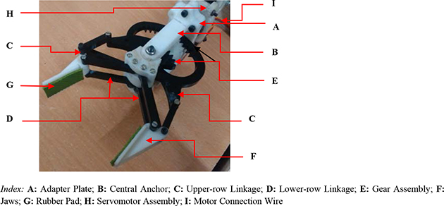
Figure 11.1. Photographic view of the link-type non-metallic jaw robotic gripper-type I.
Download figure:
Standard image High-resolution imageNow, as per the design and fabrication of LiNJRoG-I, prime source-elements for in situ vibration are at 'C' and 'D', respectively. Several design-factors are instrumental in creating this vibration: (i) lengths of the linkage-segments; (ii) fixation-elements (pin-type non-rotary attachments); (iii) span of the linkage assemblies with fully-open jaws; and (iv) method of fixation with the central anchor. Since cross-section of these linkage-elements is very small (rectangular slender section), its effect on vibration estimation was neglected for analytical modeling.
11.2.3.2. Link-type non-metallic jaw robotic gripper—type II (LiNJRoG-II)
The next hardware of link-type non-metallic jaw robotic gripper (LiNJRoG-II) that was attempted with indigenous design had more intricate semantics of the linkages. This version of the hardware was made with similar pre-requisites of the earlier one with major design alterations in the linkage system. The rest of the sub-assemblies/components were kept unaltered. The design philosophy of this variant was made with more intricate and slender structure for the upper-row and lower-row linkages. The transmission of motion from d.c. servomotor system was channelled via these linkages till the jaw-plate. Like LiNJRoG-I, here too, the fabrication process of the sub-assemblies was realized through rapid prototyping and wire-cut electro-discharge machining processes. Figure 11.2 illustrates a post-fabrication photographic view of the gripper, namely, LiNJRoG-II.
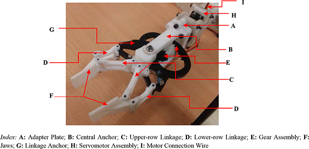
Figure 11.2. Photographic view of the link-type non-metallic jaw robotic gripper-type II.
Download figure:
Standard image High-resolution imageThe main difference in design between LiNJRoG-I and LiNJRoG-II is the element, ''G', i.e. linkage anchor. This part was fabricated as an additional item in order to provide requisite strength to the lower-row linkage pair. As illustrated in figure 11.2, design of both upper-row linkage and lower-row linkage were intricate with more slenderness added. Although this slender structure will be effective for reduction of tare-weight of the system, it will create additional metrics of in situ vibration. Hence so far as harnessing of vibration is concerned, LiNJRoG-II is more critical than its predeccessor, LiNJRoG-I.
11.2.3.3. Patient assistant miniaturized robotic gripper (PAMRoG)
The experience gathered through indigenous design and hardware development of the linkage-type robotic grippers was instrumental in taking up the design challenge of fabricating a truly miniaturized ultra-low payload two-jaw type robotic gripper. The principal design objective of this gripper was rooted at low-payload grasp with adequate form and force closure paradigms. The prototype gripper hardware was manufactured mainly to take care of various medical necessities for patient(s) at hospitals/health care centres. This gripper, christened as Patient Assistant Miniaturized Robotic Gripper (PAMRoG) works in a tiny volume, approximately 26.5 cm3, with reference to its external dimensions (length: 50 mm; width: 35 mm and breadth: 15 mm). Figure 11.3 shows the photographic view of the developed prototype of PAMRoG, wherein the novelty of miniaturized manufacturing can be ascertained. The payload capacity of this miniature gripper is nearly 800 gm, which is much consistent in comparison to its tare-weight. In fact, payload-to-tare-weight ratio is quite high for the prototype PAMRoG.

Figure 11.3. Photographic view of the patient assistant miniaturized robotic gripper.
Download figure:
Standard image High-resolution imageThe prototype PAMRoG has various characteristic features commensurate to its tiny size and actuation of the jaws. It is needless to state that because of its size miniaturization, the ensemble design is prone to a higher level of vibration, both in standalone condition of the jaws as well as during grasp. Unlike the previous two versions of flat-jaw gripper, this gripper has a backbone, called, 'base plate'. As illustrated in figure 11.3, the design of the base plate was customized keeping in mind the overall size minimization and also the optimum strategy for fitment with the robot wrist. In that sense, the function of adapter plate (as designed in the earlier two types of grippers) gets subsumed in the improvised design of the base plate of the PAMRoG. This integration is very helpful not only from the angle of size minimization but also from the standpoint of compactness and self-weight. However, with size minimization, PAMRoG is prone to acute vibration that needs to be controlled through the programming for gripper actuation. The open-loop control algorithm of PAMRoG was customized to get an assessment of the real-time vibration, generated due to the grasp-load.
11.2.3.4. Sensor instrumented miniaturized robotic gripper (SIMRoG)
The prime design semantics of PAMRoG were utilized to design a more sophisticated intelligent gripper system with adequate sensory instrumentation and minor size miniaturization. This version of our gripper, namely, Sensor Instrumented Miniaturized Robotic Gripper (SIMRoG) was also aimed at low-payload grasp with adequate form and force closure. Like PAMRoG, the prototype hardware of SIMRoG was manufactured mainly to take care of various medical necessities for patient(s) as well as tiny objects. The prototype SIMRoG works in a tiny volume, approximately 26.5 cm3, with reference to its external dimensions (length: 50 mm; width: 35 mm and breadth: 15 mm). Figure 11.4(a) shows the Computer Aided Design (CAD) model view of the developed prototype of SIMRoG, wherein the novelty of sensory instrumentation of heretogenous type may be appreciated besides intricacies of miniaturized manufacturing. The back-side view of the developed prototype with a payload (syringe) is illustrated in figure 11.4(b).The payload capacity of this miniature gripper is nearly 1 kg, which is an improvement due to better torque rating of the d.c, servomotor system used. As before, payload-to-tare-weight ratio of the prototype SIMRoG is quite high. The embedded sensor-cells, namely load cells, flexi-force sensors, infra-red sensors and strain gauges, will be helpful is real-time assessment of the vibration of SIMRoG.
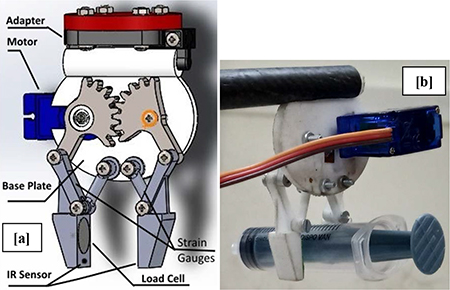
Figure 11.4. Views of the sensor instrumented miniaturized robotic gripper: (a) CAD model; (b) back-side of prototype.
Download figure:
Standard image High-resolution imageThe prototype SIMRoG has challenges from the viewpoint of sensory instrumentation and data fusion. The design is affected by in situ vibration, both in standalone mode as well as during grasp. As illustrated in figure 11.4(a), we have an additional member in SIMRoG, viz. adapter sub-assembly. The design of this adapter sub-assembly (component and fixture) was customized keeping in mind the overall size minimization and also the optimum strategy for fitment with the base plate at one end and the robot wrist on the other. Nonetheless, SIMRoG is prone to higher-level of vibration because of sensory instrumentation/wiring that needs to be abeted with the help of programming. The closed-loop sensor-infused control algorithm of SIMRoG was customized to get an assessment of the real-time vibration, generated due to the grasp-load.
11.2.4. Firmware of the curvilinear-jaw type CRGs
We will now report the firmware of three indigenously designed curved-jaw type CRGs in chronological fashion in order to unearth the design intricacies with respect to control of vibration in real-time. All of these grippers have specialties in jaw design for obvious reasons. We started the fabrication of two non-metallic type curved-jaw grippers first so as to gain confidence in tackling form closure under the purview of a small external envelope. The experience gained from the hardware manifestation of these two non-metallic grippers drove us to take up the challenge of making the metallic jaw version of the gripper for enhanced robustness of the grasp. Nonetheless, all these three varieties of CRGs were made in accordance with the sensory instrumentation, as described in earlier sub-sections. Harnessing of in situ vibration is comparatively tricky with curvilinear shape of the jaw and also overall miniaturization of the external envelope. These curvilinear-jaw grippers have been designed with gear-train type mechanism with direct transmission of motion to the jaws. Accordingly, the first two non-metallic type curvilinear-jaw grippers are labeled as: (i) Gear-driven Non-metallic Curved-jaw Robotic Gripper—Type I (GeNCRoG-I) and (ii) Gear-driven Non-metallic Curved-jaw Robotic Gripper—Type II (GeNCRoG-II). Figure 11.5 illustrates the photographic view of GeNCRoG-I and its assembled view with a small-size table-top robot. Likewise, a CAD model as well as a photographic view of the GeNCRoG-II in standalone form are shown in figure 11.6. In comparison to these two non-metallic type curved-jaw grippers, the metallic variety is more robust and slightly larger in ensemble mechanical design. Figure 11.7 illustrates the photographic view of the Gear-driven Metallic Curved-jaw Robotic Gripper, GeMCRoG along with its CAD model. The nature of vibration abetment is more or less the same as pointed out for flat-jaw type CRGs.
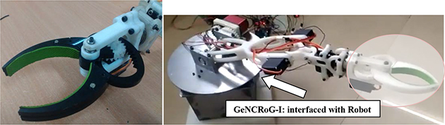
Figure 11.5. Photographic view of the gear-driven non-metallic curved-jaw robotic gripper—type I [1], copyright (2020), with permission of Springer.
Download figure:
Standard image High-resolution image
Figure 11.6. CAD model and photographic view of the gear-driven non-metallic curved-jaw robotic gripper—type II [1], copyright (2020), with permission of Springer.
Download figure:
Standard image High-resolution image
Figure 11.7. Photographic view of the gear-driven metallic curved-jaw robotic gripper and its CAD models.
Download figure:
Standard image High-resolution image11.2.5. Firmware of the contoured-jaw type CRGs
We will now describe the highlights of design and firmware of three unique variants of our CRGs having jaws with contours. The designs of these CRGs were fine-tuned with an aim towards the specific end-applications, viz. internal inspection of cylindrical pipe, flexible robotic systems and robotic welding. All of these CRGs are susceptible to run-time vibration with varying magnitude depending on the end application. The details of the hardware of these three CRGs will be described in the following sub-sections.
11.2.5.1. Rack and pinion-driven miniaturized robotic gripper (RPMRoG)
The first hardware of this kind, namely, Rack and Pinion-driven Miniaturized Robotic Gripper (RPMRoG) is meant for interfacing with a compliant universal Robotic Leech (CURL). The ensemble motion of the gripper will be serpentine, because of its assemblage with the hardware of cylindrical-shaped CURL. However, the fundamental local-frame motion of the jaws of this gripper will be linear due to the incorporation of the rack and pinion mechanism. Figure 11.8 illustrates the photographic view of the final prototype of RPMRoG and various CAD models of it.

Figure 11.8. Photographic view and various CAD models of the rack and pinion-driven miniaturized robotic gripper.
Download figure:
Standard image High-resolution imageOut of the four CAD models, model 'A' highlights the overall disposition of the gripper with base plate, adapter plate and jaw plate. Model 'B' is more focused on the design of the jaws with the external ensemble and its final fitment with the servomotor. The location of servomotor and its assemblage with the mechanical system of the gripper is crucial due to cylindrical shape of RPMRoG in order to maintain compatibility with the CURL. In fact, the compact assemblage of the servomotor may be observed in CAD models 'A' and 'B' as well as in the photographic view at the leftmost part of figure 11.8. The CAD model 'C' illustrates the indigenous design of the rack assembly of the jaws with its size compactness. This model is significant because the fittment of servomotor plays an important role in controlling the linear motion of the jaws. The last CAD model, viz, 'D' shows the relative positioning of the pinion inside the rack sub-assembly of RPMRoG. As can be idealized from the views of figure 11.8, the sources of in situ vibration are primarily at the adapter plate and base plate. These two components are thus crucial in vibration harnessing of the prototype gripper, RPMRoG.
11.2.5.2. Sensor instrumented miniaturized suspended jaw-plate robotic gripper (SIMSJRoG)
The next hardware under contoured-jaw CRG is complex design-wise, which is a very tiny lightweight system meant for assemblage with planar serial-chain Flexible Robotic System (FRS). Figure 11.9 illustrates the photographic views of the hardware of Sensor Instrumented Miniaturized Suspended Jaw-plate Robotic Gripper (SIMSJRoG), snapped from two different view-angles.
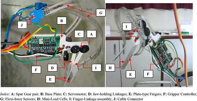
Figure 11.9. Photographic views of the sensor instrumented miniaturized suspended jaw-plate robotic gripper.
Download figure:
Standard image High-resolution imageThe prototype hardware of SIMSJRoG reveals various interesting features, pertaining to indigenously-designed jaw-plate and jaw-link sub-assembly (refer to 'E' & 'I' of figure 11.9). The jaw-plates were contoured and these were fabricated through human skill out of specialized pre-shaped material. The crux of the design is a suspended type jaw-plate, which has immense impact on the overall vibration of the gripper system. The sensory instrumentation is another feature of this gripper, wherein 2 nos. flexi-force sensors and 2 nos. mini-load cells are used, as shown in figure 11.9 (refer to 'E' & 'G'). The tare-weight of SIMSJRoG is nearly 100 gm and it can grasp a payload of 10–20 gm.
11.2.5.3. Welding instrumented sensor and spring-supported robotic gripper (WISSRoG)
Our third indigenous prototype under contoured-jaw CRG is deployed for robotic welding. This prototype is very interesting, not only because of its innovative architecture but also for its heterogenous design-modules. The prototype, namely, Welding Instrumented Sensor & Spring-supported Robotic Gripper (WISSRoG) has three design features that are characteristic to its destined task/operation in real-time. These design features are: (i) welding instrumentation; (ii) sensory instrumentation; and (iii) spring-supported actuation of jaws. Figure 11.10 shows the photographic view of the prototype WISSRoG in action (robotized arc welding). Besides the standard apparatus for arc welding and allied welding instrumentation, WISSRoG is merged with an additional sensor system for weld/grasp synthesis. This sensor system is developed with the help of 2 nos. flexi-force sensors and 2 nos. piezo-ceramic vibration sensors (refer to 'H' of figure 11.10), embedded over the monolithic gripper-body and jaws.

Figure 11.10. Photographic view of the welding instrumented sensor and spring-supported robotic gripper. Reprinted from [44], copyright (2020), with permission from Elsevier.
Download figure:
Standard image High-resolution imageThe performance of WISSRoG has significant contribution from control inputs, both welding system and sensory instrumentation. Piezo-ceramic sensors are used for the measurement of run-time vibration. These sensors are very suitable especially for low-amplitude vibration as they generate a low voltage (micro-volt level) upon external excitation. Figure 11.11(a) shows the photographic view of the piezo-ceramic vibration sensor that has been used in the prototype WISSRoG. The hardware details of the junction board of sensory instrumentation for WISSRoG are illustrated schematically in figure 11.11(b). The ensemble run-time vibration of the gripper is inevitable but can be controlled to a large extent through the spring-supported sub-assembly, designed indigenously after a series of trials.
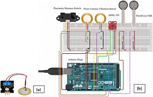
Figure 11.11. Photographic view of: (a) piezo-ceramic vibration sensor and (b) junction board for the sensors for WISSRoG.
Download figure:
Standard image High-resolution image11.2.6. Miniaturized CRGs: a wider horizon
The hardware development of Sensor-Instrumented Miniaturized Robotic Gripper (SIMRoG), described under sub-section 11.2.3.4, can be entrusted as the 'foundation' of the complete indigenous R&D on the Minaturized Complaint Robotic Gripper technology. The 'wider horizon' of the ensemble development has a total of six variants of sensor-instrumented robotic grippers, with different external dimensions and payload capacities. These six variants of SIMRoG have different challenges with respect to identification of source, estimation, measurement and harnessing of in situ vibration. However, the commonality between these six variants pertains to uniformity in sensory instrumentation for the pick-up and measurement of run-time vibration. Apart from other parameters, external dimensions (length, breadth and width) and tare-weight play great role in the assessment of payload capacity and also run-time vibration of these miniaturized CRGs. The listing of this indigenous firmware of miniaturized CRGs is provided in the table 11.1.
Table 11.1. Wider horizon of miniaturized compliant robotic grippers.
| Sl. No. | Description of the miniaturized CRG | Overall external dimensions (Approx.) | Sensory instrumentation | Tare-weight (with motor) and payload |
|---|---|---|---|---|
| 1 | Advanced sensor instrumented miniaturized robotic gripper (ASIMRoG) | Length: 45 mm; breadth: 30 mm; width: 15 mm (excluding motor) | Load cell (at jaw), flexi-force sensor (at base plate); strain gauge (at links); infra-red sensors (at jaw-tip) |
|
| 2 | Sensor instrumented curvilinear-jaw robotic gripper (SICRoG) | Length: 80 mm; breadth: 40 mm; width: 15 mm (excluding motor) | Load cell (at jaw), flexi-force sensor (at base plate); strain gauge (at base plate and links); infra-red sensors (at jaw-tip) |
|
| 3 | Sensor instrumented parallel-bar robotic gripper: type-I (SIPRoG-I) | Length: 80 mm; breadth: 50 mm; width: 15 mm (excluding motor) | Load cell (at jaw), flexi-force sensor (at base plate); strain gauge (at base plate and links); infra-red sensors (at jaw-tip) |
|
| 4 | Sensor instrumented parallel-bar robotic gripper: type-II (SIPRoG-II) | Length: 90 mm; breadth: 50 mm; width: 15 mm (excluding motor) | Load cell (at jaw), flexi-force sensor (at base plate & parallel-bar linkage); strain gauge (at base plate and links); infra-red sensors (at jaw-tip) |
|
| 5 | Sensor instrumented finger-type robotic gripper (SIFRoG) | Length: 120 mm; breadth: 40 mm; width: 25 mm (excluding motor) | Load cell (at jaw), flexi-force sensor (at base plate & finger-linkage); strain gauge (at base plate, links and fingers); infra-red sensors (at jaw-tips) |
|
| 6 | Sensor instrumented spherical-body robotic gripper (SISRoG) | Length: 50 mm; breadth: 50 mm; width: 25 mm (excluding motor) | Load cell (at jaw), flexi-force sensor (at spherical body surface); strain gauge (at jaws); infra-red sensors (at jaw-tips) |
|
The tuple of load cell, flexi-force sensor, strain gauge and infra-red sensors has dual responsibility of detection and measurement of grip force and in situ vibration of the miniaturized CRGs. The payload requirements of these grippers are commensurate to the ensemble structural layout and respective tare-weight. The extent of miniaturization, aided by advanced manufacturing processes and technologies, will play another important role in the estimation of run-time vibration of these CRGs. It is also interesting to note here that a wide variety of the miniaturized CRGs are compatible for interfacing with CRW. In other words, a cluster of mini-CRGs and CRWs is the most desirable choice for vibration attenuation and equalization of modal frequencies. We will address various design templates of CRWs now that are adaptable to design of CRGs, described hitherto.
11.3. Indigenous design of the compliant robotic wrists
11.3.1. Fundamental facets of the indigenous design
As delineated earlier, the CRW is another important element is designing intelligent grippers. A successful prototype of CRW will aid the process of vibration attenuation and smoothening of the overall control system architecture of the CRG and the industrial robotic system to a great extent. The self-vibration of CRW will be in tune with the natural frequency of vibration of the CRG, which will help harnessing the external vibration to the ensemble system. In other words, the conjugate tuple of CRW and CRG will be the most ideal and optimal combination towards dampening the run-time vibration of the robotic system. It may be mentioned here that unlike CRGs, the fundamental facets of design of CRWs are identical. The common thread of these facets is generation of enough 'compliance' inside CRW-structure, namely the housing. Hence, we have considered various indigenous designs of CRWs with sufficient variability in terms of 'type of internal members' as well as 'actuating mechanism'. Four different designs of the CRWs will be reported in this section, with reference to the relative complexity of the actuating mechanism(s) to generate compliance in serial order.
The designs of our CRWs were conceptualized from fundamentals, such as kinematics of the actuating mechanism, multi-body dynamics for compliance or infusion of non-linearity. These four designs of CRWs have been modeled and animated successfully and indigenously developed beta version prototypes have also been realized. The uniqueness of these designs with respect to harnessing of in situ counter-vibration will be described through seven different design metrics for the indigenously developed CRWs. These metrics are: (i) ensemble shape and tare-weight; (ii) kinematic layout of the internal actuating mechanism; (iii) material for fabrication: housing and compliant members; (iv) inclusion of compliance via spring or pin-joints; (v) housing (comprising of top plate and bottom plate) and arrangement for mounting the drive-motor, if any; (vi) sensory instrumentation; and (viii) adapter plate: as connection to the distal arm of the robot/robot-wrist. It may be noted that the first six of these metrics are related to functional attributes of the CRWs involving overall actuation and drive mechanism, housing and manufacturing. And, the last metric pertains to operational/run-time attribute of the CRW involving interfacing with the robot-wrist.
We will concentrate on the fundamental metrics of the indigenous designs of CRWs towards characterization and modeling of the in situ vibration. In all practical purposes, our designs of CRWs are accomplished with a cylindrical structure in compact volume, which has design similarity from the exterior with commercially available Remote Centre Compliance (RCC) devices. The fundamental objective towards conceptualizing these designs was to investigate various possible pathways of nascent compliance that will creep in to combat the vibration of the combined architecture of CRW and CRG in real-time. In fact, the designs of these CRWs are made with a consideration of intrinsic real-time compliance/counter-vibration, devoid of any external compressive forcing function. One important aspect of this in situ compliance of CRWs is its manifestation. Our novel designs of CRWs are made in a way so that a requisite and proportionate amount of compliance evolves in both axial as well as radial directions.
The first and foremost design principle that has been invoked in all of these designs of CRWs is the ensemble shape and tare-weight. The synthesis of design as well as source apportionment of inherent compliance and counter-vibration was carried out based on the ensemble cylindrical shape and housing enclosure of the CRW. Fundamentally, the cylindrical-shaped housing of our CRWs has been conceptualized with two circular plates, namely, top plate and bottom plate. Figure 11.12 illustrates the schematic disposition of the basic design metric and design-volume of the CRWs. Fundamentally, the CRW will have two Newtonian co-ordinate systems, viz. Wrist Co-ordinate System : [Xw, Yw, Zw] and Gripper Co-ordinate System: [Xg, Yg, Zg]. Our design of CRW is conceived with the association of these two co-ordinate systems with bottom plate and top plate, respectively, as depicted in figure 11.12. The actuating mechanism of the CRW, responsible for creating compliance, will be positioned within the fixed volume between these two plates under mechanical shielding.

Figure 11.12. Conceptual schematic of the ensemble disposition of the customized CRW: (a) ideal layout; (b) beta version.
Download figure:
Standard image High-resolution imageIt may be noted here that the disposition of CRW as per figure 11.12(a) is the ideal layout wherein the dimensions of the top and bottom plates are the same. However, we have adopted a slightly modified version of this layout in our beta version prototyping of the CRWs, as shown in figure 11.12(b). Herein, the dimensions of the plates are not identical and in-line with our customized design, the size of the top plate is significantly larger than that of the bottom plate. However, the cylindrical shape and dimension of the housing will remain the same in both layouts.
A wide spectrum of static dead-load was tested with these CRWs in order to ascertain the subtleness of in situ compliance with relation to the output vibration of the mating CRGs. It was found during such testings that besides tare-weight of the CRW, its ensemble shape (outer periphery) was equally contributive towards generating compliance to its own structure as well as counter-vibration to CRG. It is true that the type of external impulse/compressive force does matter significantly in ascertaining the compliance signature, the effect of which is found to be decoupled from the tare-weight or shape of the CRW. We carried out a range of experiments with the developed beta versions of the CRWs using different external compressive forcing functions through scientific weights and qualitative impulse by hand-forcing.
The next important metric of the design is the kinematic layout of the internal actuating mechanism that will be responsible for generating the mechanical motion of the CRW and also for the transmission of the in situ compliance. We have used four different kinematic chains of spring-elements for the creation of in situ compliance, once the external excitation and/or compressive forcing get imbibed through the robot-wrist. The third crucial factor of the design metric is the choice of material for fabrication of the housing and compliant members of the CRWs. We have used both metal as well as non-metal as the choice of material for the mechanical hardware of the CRWs (beta version). We did observe change in compliance/counter-vibration pattern between the CRWs made up with metallic materials vis-à-vis CRWs fabricated out of non-metallic materials (except housing). While aluminum and mild steel were used for the housing by and large, low carbon steel was used under metallic materials in some of the designs of internal components due to lower density and better mass compliance. Nonetheless, some of the designs are fabricated largely with non-metallic materials, such as nylon, teflon, ABS, polypropelene, neoprene rubber and plastic. Mass compliance was the major design yardstick in the selection of material for fabrication, based on the ensemble compliance as well as vibration characteristics of the CRWs.
The next crucial design metric under functional attribute is inclusion of compliance in the overall design of the CRW. We have customized the designs with two types of members in order to imbibe sufficient compliance in the ensemble system, namely: springs and pin-joints. Although infusing large compliance can be a dampener for vibration harnessing, we need to use a sufficient number of compliant-members in the system to ensure near-perfect counter-vibration of the CRG. The first group of member(s) for imbibing compliance is spring sub-systems that are used as intermediate members between the plates of the CRWs (refer to figure 11.12). The other group of member(s) is pin-joints that are made adhesive-type so as to have good mating contact as well as planar rotations between the axial and radial components of the CRWs.
The fifth design metric under functional attribute is fabrication of the housing of the CRW and arrangement for fixing the drive-motor, if any. The metallic housing of the CRW will comprise circular-shaped top plate and bottom plate and a mechanical shield. Although miniaturization of the housing is an issue that needs to be accomplished in order to make it compatible with the CRG, manufacturing of the housing is very straightforward. On the flip side, manufacturing of the mechanical shield, comprising a variety of spring members, will be challenging. Some of our CRWs need a drive-motor for finer actuation sequences and thus, placement of the motor inside the housing will become a big task due to the availability of relatively merged volume.
The sixth design metric under functional attribute is the sensory instrumentation of the CRW. Fitting and integration of various tiny sensor-elements play a crucial role in the design conceptualization of the CRWs. The physical size and disposition of these sensor-elements need to be accounted for and fine-tuning of the design with respect to drive and transmission system of the members inside the 'mechanical shield' of the CRWs will follow thenafter. The sensor-ensemble of the CRWs will be responsible for three types of tasks: (a) sensing of the external compressive force, either in totality or partially; (b) indication of the incipient compliance of the system; and (c) identification of the counter-vibration at various contact-zones (between CRW and CRG). The primary sensor-element that is responsible for sensing the compressive force, generated in real-time through external forcing function is semiconductor strain gauges. Ideally, we will use these strain gauges in a pair, fitted at symmetrical disposition along the radial and axial members of the CRWs in order to maintain symmetry in the sensor data/output (in milli-volt or micro-volt, depending on the magnitude of the external forcing and its point of application over the top plate. It is to be noted that the strain gauges fitted over the members will record the deflection/deformation of the CRW due to the compressive force in totality, baring loss due to instrumentation and/or white noise. However, in order to have better clarity over the compliance and counter-vibration phenomena of the CRWs in the midst of in situ vibration of CRGs, we have integrated flexi-force sensors at other locations of the CRWs as well. The flexi-force sensors at those locations will give relevant data supporting the counter-vibration forcing force in partial form. Nonetheless, these data are also important for overall understanding of the 'force closure' of the grasp phenomena by the CRGs.
The run-time attribute of the design of CRWs is the design of the adapter plate that is to be used as the direct connection with the robotic manipulator. The design of the adapter plate is critical in terms of vibration accumulation. This component is instrumental in the assessment of the overall tare-weight of the CRW as well as incipient compliance. Like CRGs, the good design practice for CRW will always be to reduce the mass of the mechanical shield sub-assembly and make it as minimal as possible just to contain the drive-motor, if any and mounting of the sensory instrumentation.
11.3.2. An overview on the varieties of indigenous designs
Various designs of CRW, the miniaturized compliant wrist, having requisite compliance in axial and radial directions, have been developed by the author's group. Out of several feasible layouts, indigenous design of four representative CRWs will be reported here. These designs and subsequently beta version prototypes can be classified on the basis of the layout of multiple number spring elements in axial and radial directions. Accordingly, our indigenously designed and customized CRWs are grouped on the basis of the disposition of spring-elements, viz. (a) compression spring-elements; (b) passive spring-elements; (c) pneumatic spring-elements and (d) sensor-based spring-elements. It is to be noted that in all of the four schemes, the compliant members (i.e. the springs or the spring-like elements) need to be placed between the two plates inside the housing, namely top plate and bottom plate (refer to figure 11.12(a)). However, the dimensions of these elements will be governed by the size of the bottom plate (refer to figure 11.12(b)). As illustrated in figure 11.12, an outer membrane will house the plates and the spring-systems inside and will act as a mechanical shielding. Pathways for sensory instrumentation for the pick-up of compressive force and deformation of CRW will also be accommodated inside the said housing. Strain gauge-based instrumentation has been invoked for the quantitative analysis of the deformation rheology as well as estimation on the resonant frequency (as a measure of counter-vibration for the CRG).
The nucleus of our indigenous design of CRWs is assimilation of sensor-instrumented 'spring-elements' in radial and axial directions. This sort of symmetric disposition of the spring-elements ensures the spread of the compressive force evenly inside the mechanical shielding. Fulfilment of this criterion also signifies somewhat even distribution of compressive force inside the housing and deflection in the members thereafter. Spring-element-based sensor-instrumented members will be evenly disposed in axial and radial directions; which will be four nos. each in three of our designs. This number can be altered depending upon the ensemble size of the CRW and its physical attachment with the CRG. We have used three types of 'spring-like elements' in our designs: (a) passive spring; (b) pneumatic spring; and (c) sensor-based spring. The passive spring-based system invokes miniature pneumatic cylinders while pneumatic spring-based system is essentially a self-instrumented fluidic muscle. The sensor-based spring system is conceptualized with various elemental parts and sensors in assemblage. By virtue of the design, the characteristic motions of these spring-based members will be non-linear and coupled. Sizes of the spring-based members are indeed crucial, and have been finalized through topology optimization. The backbone structures of the spring-elements in all of these designs are made with non-metallic materials for weight reduction. It may be mentioned here that all of these four designs of CRWs are unique in their respective work-envelope, control semantics and counter-vibration protocol (aided by control programming for the CRGs). The layout of the spring-elements in axial and radial directions was made in such a way as to conform to the external shape of the CRW as well as its incipient undulation and/or elastic deformation. The vibrational paradigm of the CRW is dependent on the input-motion, as receivable from the external excitation in real-time.
11.3.3. Details of the firmware
We will elucidate on the fundamentals of the firmware of the four variants of our CRWs in this section. Since these customized CRWs are more sensitive with respect to internal mechanisms, we will focus the detailing on those mechanisms while dealing with the harnessing of vibration of CRGs.
11.3.3.1. Compression spring-element-based robotic wrist (CSRoW)
The compression spring-element-based CRW has been designed with a total of eight 'compression spring-element members', spread out equally along axial and radial directions with uniform angular spacing. All of these members are of identical dimensions as well as content. Figure 11.13 shows the schematic view of CSRoW, with major external dimensions as per the beta version firmware.

Figure 11.13. Schematic view of compression spring-element-based robotic wrist.
Download figure:
Standard image High-resolution imageThe inset of figure 11.13 illustrates the actual disposition of four axial springs (A1 to A4) and four radial springs (R1 to R4) inside the mechanical shielding of CSRoW. The relative positioning of the axial and radial springs is important from the point of view of assembling the spring-elements at an equal angular spacing of 45°. The height of the mechanical shield of CSRoW is also crucial in determining the transmission route for the external compressive force. The assembly of one representative compressive spring-element spring will consist of one compression spring and two strain gauges at both sides of the spring (disposed symmetrically). The assembly will be attached with the top and bottom plates as rigid 'pin' type attachments. Figure 11.14 illustrates the schematic view of a representative spring assembly of CSRoW.
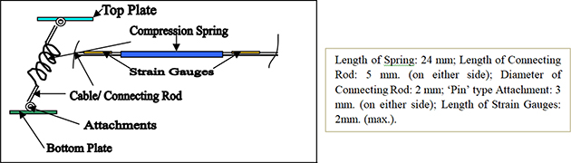
Figure 11.14. Schematic view of a representative spring assembly of CSRoW with hardware specifications.
Download figure:
Standard image High-resolution image11.3.3.2. Passive spring-element-based robotic wrist (PSRoW)
The passive spring-element-based CRW has been designed with a total of eight 'passive spring-element members', spread out equally along axial and radial directions with uniform angular spacing. All of these members are of identical dimensions as well as content. However, hardware manifestation of 'passive spring' is skill-based and tricky from the point of view of manufacturability. Figure 11.15 shows the schematic view of the Passive Spring-element-based Robotic Wrist, PSRoW, with major external dimensions as per the beta version firmware.
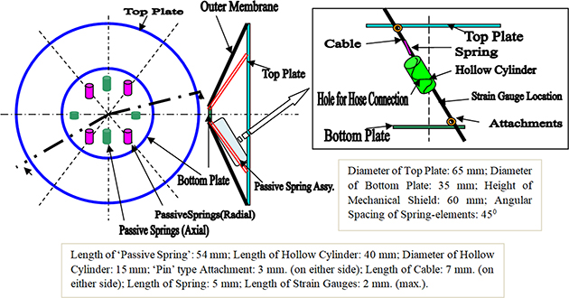
Figure 11.15. Schematic view of passive spring-element-based robotic wrist with hardware specifications.
Download figure:
Standard image High-resolution imageUnlike the previous design of CSRoW, the assembly of 'Passive Spring' calls for engineering skill on hardware realization. The passive spring is constituted from: (i) hollow tube (in the form of a hollow cylinder); (ii) spring; and (iii) sensing element, i.e. strain gauge. As illustrated in figure 11.15, the final assembly of the passive spring will be attached with the top plate and bottom plate through 'pin'-type attachment. The hollow tube, actuated through pneumatics, will aid the spring in subsuming externally-applied compressive force. Two strain gauges will be mounted on the connecting cable of the passive spring assembly, equally disposed on either side of the hollow tube. The strain gauges will sense the deflection of the respective passive spring system(s) and will show cumulatively the overall undulation of the top plate of the CRW.
The hollow tubes of PSRoW will be actuated by means of small-sized moderate stroke-length double acting pneumatic cylinders of miniaturized size. Thus, the ensemble pneumatic circuitry of PSRoW will comprise of eight double-acting cylinders, a solenoid-based actuation system, pressure-regulating valves, pressure relief values and allied instrumentation. Now, depending upon the fluid pressure inside the hollow cylinders and the corresponding flotation of those, the spring will be either compressed or elongated. This will doubly ensure the compliance in the system and the corresponding deflection (of the passive spring) will be sensed by the strain gauges. The hollow cylinders will have inlet hole, suitable for fixing the hose and the other end of the (flexible) hose will be attached to the double-acting cylinder.
11.3.3.3. Pneumatic spring-element-based robotic wrist (PuSRoW)
The third innovative design, namely the pneumatic spring-element-based CRW, has been designed with a total of six 'pneumatic spring-element members', arranged in a symmetric matrix of Stewart Platform layout along axial and radial directions with uniform angular spacing. In other words, the six pneumatic spring members will be placed at equal angular intervals in a regular hexagon. All of these members are of identical dimensions as well as content. However, hardware manifestation of the 'pneumatic spring' is also a skill-based activity like the 'passive spring' in PSRoW. As a matter of fact, manufacturing of these pneumatic springs is even harder than in the case of passive springs. Figure 11.16 shows the schematic view of the Pneumatic Spring-element-based Robotic Wrist, PuSRoW, with major external dimensions as per the beta version firmware.
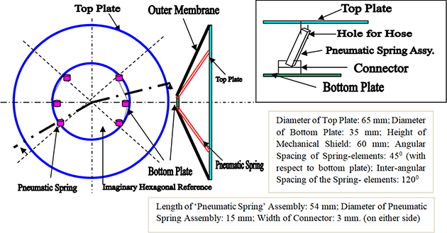
Figure 11.16. Schematic view of pneumatic spring-element-based robotic wrist with hardware specifications.
Download figure:
Standard image High-resolution imageSince the pneumatic springs are essentially fluidic muscles, these members do not need any other sensory system. Thus, there is no need of mounting a separate sensing element in PuSRoW, as pneumatic springs are capable of sensing the fluid pressure applied on the respective element. The system compliance of PuSRoW will be manifested by the extension/compression of the pneumatic spring-elements. In summary, these pneumatic springs will function like single-acting actuators. The inset of figure 11.16 schematically illustrates the positioning and fixation of the pneumatic spring with the top and bottom plates of PuSRoW.
11.3.3.4. Sensor-based spring-element-driven robotic wrist (SeSRoW)
The fourth novel design, namely, sensor-based spring-element-driven CRW has been designed with a total of eight 'customized spring-element members', arranged in a radially-symmetric layout along axial and radial directions with uniform angular spacing. The 'customized spring' elements have been designed and fabricated from a very thin plate with sensing element mounted on it. The optimal design of sensor-based spring-element-driven robotic wrist, SeSRoW, will incorporate four customized springs, along radial and axial directions. All of these members are of identical dimensions as well as content. However, hardware manifestation of a 'customized spring' is also a skill-based activity like the 'passive spring' in PSRoW or 'pneumatic spring' in PuSRoW. Figure 11.17 shows the schematic view of the SeSRoW, with major external dimensions as per the beta version firmware.
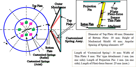
Figure 11.17. Schematic view of sensor-based spring-element-driven robotic wrist with hardware specifications.
Download figure:
Standard image High-resolution imageIt may be noted that the change in output response (in milli-volts) of the flexi-force sensors (placed inside these sensor-based spring members) will represent the overall undulation of the top plate, i.e. the wrist assembly in general. Unlike other schemes of CRW, the sensor-integrated spring members of SeSRoW will be 'free' at one end, namely, in the direction of the top plate (refer to the inset of figure 11.17). However, the other end of the member, viz. along the bottom plate, will be anchored via a 'pin'-type attachment. One interesting design-metric of SeSRoW is the augmentation of 'Projection Pins' underneath the top plate, which will induce vibration/excitation to the sensor-integrated spring members. The overall disposition of the customized spring assembly has been made commensurate with the height of the mechanical shield of SeSRoW.
11.4. Grasp-induced vibration models of the compliant robotic grippers
11.4.1. An overview of vibration synthesis
Real-time functionalization of a CRG is, no doubt, highly challenging from the purview of control system architecture. In fact, control of CRG is one of the niche ensembles of present-day robotics research that deals with various modes of vibrations, inherent in the system. The vibration, so referred, is completely built-in type and thus it is design invariant. By nature, this very vibration in CRG is self-propagating and does not follow analytical modeling and rule-base in practically all end applications. As delineated in section 11.2, our novel CRGs do have an advantage of very low tare-weight that is quite befitting for a large number of applications. But, on the flip side, the major bottleneck is the inherent vibration of the units. And, due to this inherent aspect of CRG, prototyping multiple degrees-of-freedom customized compliant gripper is highly challenging.
Several designs of CRG have been attempted by the researchers in the past decade in order to alleviate this vibration but most of those trials have been unsuccessful. In contrast to previous vibration-combatting modeling attempts, our endeavour for vibration synthesis of CRG will be in a holistic fashion that caters for real-time aspects like rheology (stress-strain paradigms), in situ vibration, sensor fusion and non-linear coupled dynamics for control.
The domain of VS is branched out into two interlinked domains: (i) Grasp Synthesis (GS) and (ii) Real-Time Dynamics (RTD). The present treatise reports modeling of this in situ vibration as well as solving design issues for the firmware of customized CRGs. It is needless to state that this novel modeling for the run-time synthesis of customized miniature CRGs will be carried out with an aim towards analytical modeling for GS and RTD. Fundamentally, an ensemble of GS will be governed by the appropriate 'grasp model', involving the principles of form closure and force closure. With this backdrop, the domain of GS comprises three fundamental paradigms, viz. (a) object geometry; (b) contact mechanics-based model; and (c) gripper kinematics. Thus, modeling for GS will revolve around the tuple of object and gripper, involving geometrical and kinematic features. Semantics of contact mechanics is the key for the formulation of GS in run-time condition of the CRG. The facets of RTD are complementary to that of GS and these are more focused towards the vibration signature aspect during the robotic grasp. The domain of RTD is developed with the help of three metrics: (a) vibration signature (natural frequency and Eigen vectors); (b) dynamic model of the gripper; and (c) turning model of the gripper. We will now go through the details of GS and RTD in subsequent sections.
11.4.2. Paradigms of grasp synthesis
GS for compliant robotic grippers dwells primarily with 'grasp prehension', which occurs through four cases of realization of the external geometry of the jaw surface and object surface. A grasp-induced vibration model will depend on the specific type of this prehension in real-time. Hence, geometrical features of the external surfaces of the CRG-jaws as well as the object being gripped are very crucial in building up this model. Of course, the process of this modeling will involve smooth transformation of surface geometry from a pure geometrical standpoint to analytical perspectives.
We will detail the analytical model for two types of jaws of our CRGs, as described in section 11.2, namely (a) flat jaw and (b) curvilinear jaw. Likewise, two envelopes of the object surfaces will be considered in the modeling. As per the basic proposition of our model, we need to consider the 'circular envelope' for flat-surfaced objects. Similarly, 'curved approximation' of flat jaw will be adhered to for flat-jaw gripper. However, we do not need any curvilinear approximation for curved-jaw CRGs, as the geometries are already defined. And, analytical treatment for objects having curved surface will be straightforward also. Hence, the strategy for modeling is based on the analytical treatment of both jaws as well as object surfaces as curves.
The advantage of this sort of modeling is the subtlety of the point of contact between the mating surfaces of the gripper jaw and object grasped. Our grasp-induced model will consider a 2-D planar model for the mating between CRG-jaw and the object, and thus we will require co-ordinate location of the said 'point of contact' for easy identification of the centroid for the form closure of the grasp. Accordingly, four cases of 'grasp prehension' can occur as per our modeling semantics, viz. (a) Case I: Curvilinear Jaw surface and Curved Object (CJCO); (b) Case II: Curvilinear Jaw surface and Flat-surfaced Object (CJFO); (c) Case III: Flat Jaw-surface and Curved Object (FJCO); and (d) Case IV: Flat Jaw-surface and Flat-surfaced Object (FJFO). It may be noted that while Case I and Case II are valid for Curvilinear Jaw Gripper, Case III and Case IV are valid for Flat Jaw Gripper.
We will delineate three types of grasp models: (A) Asperity Contact-based (applicable for FJCO and FJFO types of grasp); (B) Contact Mechanics Vector-based (applicable for all four types of grasp); and (C) Adhesive Mechanics-based (applicable for CJCO and CJFO types of grasp). The details on the formulation of these three grasp-induced vibration models are presented below.
11.4.3. Development of the grasp models
11.4.3.1. Asperity contact-based grasp model (ACGM)
The Asperity Contact-based Grasp Model (ACGM) is applicable essentially for flat-jaw CRGs towards comprehending FJCO and FJFO types of grasp. The asperity contact analysis of the flat-jaw compliant robotic gripper and its postulation thereof is realized through polynomial syntax of the surfaces of the object and gripper. Prior to dealing with the subtlety of the model, we will first look at the contact condition between the gripper-jaw and the object from an analytical viewpoint. Figure 11.18 explains the scenario of the contact condition, prevailing at the gripper–object interface, at the instant of grasping.
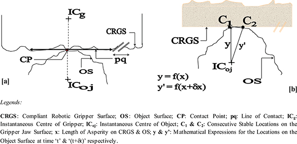
Figure 11.18: Schematics of the contact facets of ACGM, vide (a) asperity contact and (b) stability during contact.
Download figure:
Standard image High-resolution imageIt may be noted here that while the final asperity-level contact demarcates the location of the contact point, CP, its position gets defined by the line of contact, pq, It may be noted here that while the final asperity-level contact demarcates the location of the contact point, CP, its position gets defined by the line of contact, pq↔, which is the common tangent between CRGS and OS. On the other hand, both C1 and C2 are equally likely locations on the Jaw surface of CRG, from the stability aspect. In general, CRGS and OS can be expressed mathematically in y = f(x) form using polynomials in a 2-D Cartesian co-ordinate system. The respective first derivatives of the said polynomials for CRGS and OS must be identical for a perfect asperity contact at the line of contact of object(s) to be grasped. The following two lemmas can be proposed in extension to the concept of ACGM:
LEMMA 1:
While first derivatives of the said polynomials ensure a stable grasp, the second derivatives signify slip-free grasp.
LEMMA 2:
The higher-order derivatives are therefore, non-entity, as both 'force closure' and 'form closure' of robotic grasp are ensured.
Analytically 'y1' and 'y2' represent the CRGS and OS, respectively, composed by sets of polynomial coefficients, vide {a0, a1,....,an } and {b0, b1,....., bn } that can be expressed in polynomial series form as shown below:


and,

Now, the relative displacement vector between the gripper and the object, [δgoj ] can be expounded with respect to displacement vectors pertaining to gripper and object separately as,

Now, for flat jaw surface of CRG, [δg ] will be zero and in those cases (vide Case III and Case IV of section 11.4.2:: FJCO and FJFO), [δoj ] is evaluated as,

The final computing expression for [δgoj ] after simplification will be:

It is important to realize the physical significance of [δgoj ] in light of the posterior calculation of the grasping force per unit length of the CRG-jaw under run-time vibration scenario. The uniqueness of our CRGs is the uniform distribution of force concentration matrix over the jaw surfaces so as to ensure a perfect force closure and also, form closure. The computed value of the grasping force per unit length of the jaw surface or the ensemble grasping force in case we can determine the total surface area of the CRG-jaws will be the deciding factor for estimating the natural frequency of vibration of the CRG.
The force concentration matrix will be modeled as a concentrated force vector in 2-D, wherein the resultant force vector passes through the centroid of the force closure. We will use Newtonian frame of reference for the modeling of this force concentration vector, {Bg } and accordingly, the distribution of {Bg } will be, {Bg } = [Bg_x 2 + Bg_y 2]1/2, in a simplified form, having its dimension as ML−1 T−2 (=> Force/Area : MLT−2/L2).
Thus, we get the final expression for the grasping force per unit length under ACGM as,

It may be noted that we have excluded the higher-order terms in equation (11.5) in order to avoid computational complexity. The formulation of equation (11.5) is dependent on the value of 'x' and the numerical quantification of the Cartesian components of {Bg }. In fact, both Bg_x and Bg_y can be evaluated through experimentation on grasp performance of the CRGs, through the readings of load cells and/or strain gauges.
11.4.3.2. Contact mechanics vector-based grasp model (CMVGM)
The Contact Mechanics Vector-based Grasp Model (CMVGM) is applicable for all four types of grasp prehensions, viz. CJCO, CJFO, FJCO & FJFO. The point-contact phenomena between object and gripper jaw surfaces and postulation thereof will be evaluated in this model through two distinct methodologies: (a) Contact Vector Approach and (b) Talyor series-based Approach. CMVGM is primarily devised on the aspects of 'point contact' pheonemoa, which is a deviation from the 'asperity contact' scenario. Hence, we will delineate the postulation of CMVGM under two approaches on the basis of Point Contact-based Contact Mechanics model for the graspable object. From the proposition of asperity-based contact model in sub-section 11.4.3.1, let us take a detour to look at the scenario of contact mechanics at a slightly larger level. The present model, CMVGM, is effective in analyzing the grasp phenomena in real-time, which is based on the metric of contact vectors between the gripper surface and object surface. Figure 11.19 schematically illustrates the postulation of the model, highlighting the nature of contact (mating) prevailing in the CRG and the object(s) to be gripped.
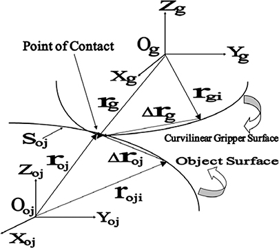
Figure 11.19. Schematics of the contact mechanics vector-based grasp model of CRGs.
Download figure:
Standard image High-resolution imageThe following nomenclatures are used in the formulation of the model (CMVGM):
- [Xg , Yg , Zg ]T : Newtonian/Cartesian Co-ordinate system of the gripper;
- [Xgi , Ygi , Zgi ]T : as above, at the ith time-instant;
- Og , Ogi : respective origins of the above systems;
- [ rg ]: contact radius vector of the gripper;
- [ rgi ]: as above, at the ith. time-instant;
- δθgi : angular shift in position at the ith. instant;
- [Bg ]: force concentration matrix of the gripper;
- [Xoj , Yoj , Zoj ]T : Newtonian/Cartesian co-ordinate system of the object;
- [Xoji , Yoji , Zoji ]T : as above, at the ith. time-instant;
- Ooj , Ooji : respective origins of the above systems;
- [roj ]: contact radius vector of the object;
- [roji ]: contact radius vector at the ith time-instant;
- δθoji : change in angular position of the object;
- [r(s)]: generalized radius vector at the gripper-object contact surface;
- Soj : curvilinear segment at the contact-zone of the object and gripper.
It is to be noted that details of [Xgi , Ygi , Zgi ]T , [Xoji , Yoji , Zoji ]T , Ogi , Ooji , [r(s)], δθgi and δθoji are not shown in figure 11.19 explicitly in order to avoid cluttering. The significance of these legends will be amplified in the modeling. Also, origins of the systems (for object and gripper) are meant for calculating the contact radius vectors only; those are not the actual centres of the respective objects.
With this general schema in the background, now we will adopt two approaches for building up this contact mechanics-based model for grasp synthesis, as stated earlier. The first approach is based on vector signature of various domain-indices and grasp-related parameters, such as roj , roji , rg , rgi etc, wherein we will develop expressions and equations in co-planar vectors. The second approach is based on Taylor series expansion of the domain-indices and grasp-specific parameters, as stated before.
11.4.3.2.1. Contact mechanics-based model: vector signature-based approach
In this method, we will develop vector expression for the grasp-related parameters by considering two-dimensional simplification of the above paradigm, as depicted in figure 11.19. Thus, we have the following two vector representations (using standard direction cosines) for the object surface:


where,

{i, j} are the respective unit vectors along X and Y axes.
Likewise, the vector representation for the gripper surface will be:


where,

As before, {i, j} are the respective unit vectors along X and Y axes.
Hence, we can compute the differential radii vectors, Δroji and Δrgi for small angular deviations as follows:

In-line with the formulation of equation (11.8), we can deduce the following for the gripper surface:

Therefore, we get the algebraic expression for (Δroji −Δrgi ) as:

Hence, relative displacement vector between the gripper and the object can be simplified as,

Considering the distribution of force concentration vector of the gripper [Bg ] in 2-D planar matrix as, [Bg ] = Bg_x i + Bg_y j, in a simplified form, having its dimension as ML−1 T−2 (=> Force/Area: MLT−2/L2), we get the final expression for the grasping force per unit length (of the gripper) as,

The final formulation of grasping force of the CRG per unit length of the jaw surface, as per equation (11.12) clearly shows the parlances of point contact-based grasp with in-built force concentration vector.
11.4.3.2.2. Contact mechanics-based model: Taylor series-based approach
Let us consider the geometry of figure 11.19 again and have a close look over 'Soj '. Now, from the geometry we can expound Δroji in the form of Taylor Series as:

On simplification, the equation yields to:

By taking into account all four cases of grasp, namely, CJCO, CJFO, FJCO & FJFO, we can arrive at an approximation towards parametric modeling for the curvilinear pattern of the grasp (pick) at the jaw surface of the compliant gripper after a successful pick-up yields the following equation:

where, ϕ denotes the angle of shift, measured between the tangents at the inside and outside boundary curves, as conceptualized in figures 11.19 and k1, k2 are numeric parameters, vide {k1, k2} ∈ (0,1).
Thus, on simplification of equation (11.15), δSoj (equals δs) can be approximated as,

Using the same analogy of equation (11.11), as stated earlier in sub-section 11.4.3.2.1, we get the relative translation of the gripper with respect to the object as,

It may be noted here that the contact radius vector of the object, roj (s) and its complimentary on the gripper surface, i.e. rg (s) are identical. Both roj (s) and rg (s) are equal to and the same as r(s), which is the contact radius vector between the gripper and object surfaces.
Considering the distribution of force concentration vector of the gripper [Bg] in 2-D planar matrix as, [Bg] = [Bg_x 2 + Bg_y 2]1/2, in a simplified form, having its dimension as ML−1 T−2 (=> Force/Area : MLT−2/L2), we get the final expression for the grasping force per unit length as,

Here too, the final formulation of grasping force of the CRG per unit length of the jaw surface, as per equation (11.18) shows the paradigms of point contact-based grasp with in-built force concentration vector without ambiguity.
11.4.3.3. Adhesive mechanics-based grasp model (AMGM)
The Adhesive Mechanics-based Grasp Model (AMGM) is applicable for all curvilinear jaw-type grippers with two types of grasp prehensions, viz. CJCO and CJFO. The point-contact phenomena and postulation thereof, as expounded in sub-section 11.4.3.2, can be extended to another important dimension wherein we need to provide a technological solution for gripping of: (a) very lightweight and tiny objects; (b) cluster of tiny objects in soft encapsulation and (c) consortia of micro-substances in permeable covering with the help of a curvilinear jaw compliant robotic gripper. The subtle point-contact phenomena between object and gripper jaw surfaces in such small lightweight objects or soft encapsulation of multiple tiny objects will be evaluated in this model through two distinct methodologies: (a) Contact Vector Approach and (b) Talyor series –based Approach.
At times, these tiny objects are typical in shape and made of customized design. Likewise, in cases where specific tiny/micro-objects are put under suitable soft encapsulations, e.g. polythene packets, gel-like covering, soft epoxy coating etc, we need to use a specific gripper-jaw as well as grasp model based on adhesion-type mating. Hence, we need to study the design features of such objects/encapsulated object-mass in detail, before going through the postulation of the grasp model. In general, for curvilinear objects, we will consider inner and outer radii for the modeling. The quantum of force concentration vector of the gripper and its dissipation over the jaw surface will depend on the shape and contour of the curvilinear jaw gripper. The ensemble of force concentration and dissipation will be guided by the adhesive mechanics-based model of the grasp action.
The parametric analysis has been made having inputs on the contact mechanics of the mating parts and the kinetics of the gripping action. Thus, the model postulates the formulae for the quantitative estimation of the gripping force as a function of various geometric parameters of the tiny object(s) and the gripper. The 'object' is assumed to have curved surface with marginal thickness, approximated through mathematical function. However, the model is equally applicable for objects with flat surfaces. Since the nature of grasp is analyzed using the ideation of adhesive-contact (between gripper surface and object surface), we will adhere to the systematic procedure of using location vectors for the respective surfaces. The force of gripping gets initiated from the in-built stiffness of the contact-zone. We will model this stiffness in the pathway of spring stiffness, using vector form. Thus, the present model, AMGM is essentially a point contact-based model with in-built force concentration vector plus stiffness vector ('adhesion'). Figure 11.20 illustrates the geometrical paradigms of the adhesive (contact) mechanics-based grasp of the CRG.

Figure 11.20. Schematics of the adhesive mechanics-based grasp model of CRGs.
Download figure:
Standard image High-resolution imageWe have used the following nomenclatures in developing the AMGM:
- [Xgr , Ygr , Zgr ]T : Newtonian/Cartesian Co-ordinate system of the gripper;
- [Xgri , Ygri , Zgri ]T : as above, at the ith time-instant;
- Ogr , Ogri : respective origins of the above systems;
- [rgr ]: contact radius vector of the gripper;
- [rgri ]: as above, at the ith time-instant;
- δθgri : angular shift in position at the ith instant;
- [Bgr ]: force concentration vector of the gripper;
- [Kgr ]: stiffness matrix of the gripper;
- [B-K]gr : resultant force vector at the gripper;
- [Xoj , Yoj , Zoj ]T : Newtonian/Cartesian co-ordinate system of the object ;
- [Xoj , Yoji , Zoji]T: as above, at the ith time-instant;
- Ooj , Ooji: respective origins of the above systems;
- [roji ]: contact radius vector at the ith time-instant;
- δθoji : change in angular position of the object ;
- [r*(s)]: generalized radius vector at the gripper-object contact surface;
- Rgi : inner radius of the gripper 'adhesion-zone';
- Rgo : outer radius of the gripper 'adhesion-zone';
- Rgm: mean radius of the gripper 'adhesion-zone';
- Sgr : curvilinear segment of the gripper surface at the contact-zone;
- Soj : curvilinear segment of the object surface at the contact-zone.
It is to be noted that details of [Xgri , Ygri , Zgri ]T , [Xoji , Yoji , Zoji ]T , Ogri , Ooji , [r*(s)], Rgm , Rgi , Rgo , δθgri and δθoji are not shown in figure 11.20 explicitly in order to avoid cluttering. Like the previous case of Contact Mechanics-based model, the significance of these legends will be amplified in the modeling. It may also be noted that the origins of the systems (for the object and gripper) are meant for calculating the contact radius vectors only; those are not the actual centres of the respective entities. We will proceed for developing the Adhesive Mechanics-based model for grasp synthesis using two approaches, namely, (a) Vector Signature-based approach and (b) Taylor series-based approach. The expressions and equations will be developed in co-planar vectors under Vector Signature-based approach. In contrast, the second approach is based on Taylor series expansion of the domain-indices and grasp-specific parameters. In both the approaches, we will investigate the final expression of the gripping force in X, Y and Z directions through 'Part-Mating' Model, using 'Adhesive Mechanics'. We will postulate the specific modeling thematics under these two approaches in the next sub-sections.
11.4.3.3.1. Adhesive mechanics-based model: vector signature-based approach
As explained earlier, Vector Signature-based approach relies on vector signature of various domain-indices and grasp-related parameters as per the indices of figure 11.20, such as roj , roji , rgr , rgri etc. Considering two-dimensional simplification of the grasp paradigm, we can arrive at the following equations for the geometry of the gripper (using standard direction cosines),


where,

Likewise, the vector representation for the object surface will be:


where,

In both of the above sets of formulation, {i, j} are the respective unit vectors along X and Y axes.
Hence, we can compute the differential radii vectors, Δroji and Δrgri for small angular deviations as follows:


Therefore, we get the algebraic expression for (Δroji−Δrgri ) as:

Hence, relative displacement vector between the gripper and the object can be simplified as,

In this model, apart from force concentration vector, the adherence of the objects inside the gripper adhesive-zone is primarily due to the contact stiffness of the gripper surface. In that respect, we will encounter a coupled effect of 'Force Concentration Vector' and 'Spring-like Contact Force', applicable at the 'adhesive zone' of the gripper. We will consider the resultant of these two vectors for the final modeling of the grasping force per unit length of the gripper surface.
We will consider the distribution of force concentration vector [Bgr ] (dimension: ML−1 T−2) and spring stiffness vector [Kgr ] (dimension: MLT−2/L → MT−2) as,


The resultant force per unit area of the gripper, [B-K]gr , having its dimension as ML−1 T−2 (=> Force/Area: MLT−2/L2), will be computed approximately as:

The above expression for [B-K]gr is slightly non-optimal in the sense that we have approximated the circumference of the gripper 'adhesive-zone' as a smooth circular zone of radius Rgo . But since this 'adhesive-zone' is an exact replica of the object being grasped, we need to fine-tune this expression in the final calculation of the grasping force per unit length of the gripper. The number of 'adhesive-zones' in the gripper-object contact plane will be instrumental in this recast calculation. The 'circumference' of the ensemble 'adhesive-zone' will not be smooth circular, but, a cumulative factor.
We will now go through the engineering metrics of the 'adhesive-zones' in order to proceed further with the grasp model, AMGM. Fundamentally, the concept of 'adhesive-zones' will occur in cases of grasping amorphous and/or soft tiny objects, such as cotton-ball, wool, small garments etc. Besides, we will come across the concept of 'adhesive-zones' in situations of grasping multiply tiny/micro-objects inside soft encapsulation, such as safety-pins, clips, nails, buds, threads, needles in isolation/clustered form inside poythene/plastic wrappers. The tuple of 'adhesive-zones' will be viable also for micro-objects encapsulated in gel-like covering/wrapper. Additionally, the principle of 'adhesive-zone' will be effective for tiny substances covered by soft epoxy amorphous outer casing. As a matter of fact, today's manufacturing arena is booming with efficient and accurate handing of such critical components under soft outer coverings. These activities in industry come under the purview of robotized gripping, by and large, governed by a fine-tuned grasp modeling and control algorithm/gripper program. Our conceptualization of Adhesive Mechanics will be instrumental in analyzing grasp phenomena of such components/cluster of objects/consortia of micro-substances. Figure 11.21(a) schematically illustrates the disposition of multiple adhesive-zones that will be formed over the surface of a soft tiny object/amorphous substance/cluster of micro-objects inside soft encapsulation/consortia of micro-substances in a permeable capsule. Some representative photographic views of these objects are shown in figure 11.21(b) for ready reference.

Figure 11.21. Disposition of multiple adhesive-zones during grasp: (a) schematic; (b) real-life view of the graspable objects.
Download figure:
Standard image High-resolution imageIt is interesting to note the varieties of graspable objects that follow the principle of 'adhesive-zone' during grasp, as illustrated through 11 representative views under three groups, viz. (a) amorphous and soft objects; (b) cluster of tiny objects in soft encapsulation; and (c) consortia of micro-substances in permeable capsule. Multiple adhesive-zones will be formed during grasp of 'amorphous and soft objects (# 1 to 4 of figure 11.21(b)) irrespective of the form of gripping. In contrast, defined number of adhesive-zones will be created during grasp of soft-encapsulated objects (# 5 to 9 of figure 11.21(b)) and consortium of objects under permeable covering (# 10 and 11 of figure 11.21(b)). However, exact number of adhesive-zones will be dependent on the type, dimension and natural coherence of the objects. At times, it will also vary depending on the nature of encapsulation.
Considering number of 'adhesive-zones' in the gripper as Ngr , the analytical expression for the circumference of the 'gripper-object contact plane' Cgr will be (refer to the geometry of figure 11.21(a)):

Accordingly, we get the final expression for the grasping force of the gripper per unit length as,
Hence, the ensemble grasping force for the entire gripper will be:

The mean radius of the 'adhesive-zone' of the gripper is the measured for the developed circumference of the 'adhesive-zone' and accordingly, the ensemble grasping force can be computed quickly using Rgm as input.
It is to be noted here that being very small in size, the evaluation of Fgr needs to be further substantiated by the 'part-mating model', as applicable for the 'adhesive-zone'. Accordingly, we will be able to find analytical expression for the X, Y and Z components of Fgr , namely, [Fgr ]X , [Fgr ]Y and [Fgr ]Z using the parlances of the said 'part-mating model'.
11.4.3.3.2. Adhesive mechanics-based model: Taylor series-based approach
Let us consider the geometry of the 'adhesive-zone' again and have a close look over 'Soj ' and 'Sgr ' (refer to figures 11.20 and 11.21(a)). Now, from the geometry we can expand Δroji in the form of Taylor series as:

On simplification, the above equation yields,

Now, from the geometry of the 'adhesive-zone', we have,

On simplification, the above equation yields,

An approximation for parametric modeling for the curve pattern of the 'adhesive-zone' yields following equations:


where, 'υ' denotes the angle of twist, measured between the tangents of the inner and outer curves and {koj , loj , kgr , lgr } are numeric parameters ranging between 0 and 1, i.e. {koj , loj , kgr , lgr } ∈ (0,1).
It is to be noted here that the geometric equation for the boundary curve will be identical for both object and gripper ('adhesive-zone'). As we are modeling the contact mating phenomenon, previous equations will hold true for either of the mating members.
Differentiating equations (11.35a) and (11.35b) we get,


Thus, on simplification, the algebraic expression for 'ds' under the respective cases of object and gripper ('adhesive-zone') can be approximated as,


Thus, we get the final expressions for differential translation of the object and gripper adhesive-zone as,


And, we get the relative translation of the gripper adhesive-zone with respect to the object as,

Considering the modulus values of the force concentration vector of the gripper [Bgr ] in 2-D planar matrix as, [Bgr ] = [Bgr_x 2 + Bgr_y 2]1/2 and that of the stiffness vector [Kgr ] in 2-D planar matrix as, [Kgr ] = [{Kgr_x 2/Cgr 2 }+ {Kgr_y 2/Cgr 2} ]1/2, we get the final expression for the grasping force per unit length as,
Hence, the ensemble grasping force for the entire 'adhesive-zone' of the gripper will be:
Equation (11.43) uses two different limits of integration, while estimating the ensemble grasping force of the gripper adhesive-zone. Unlike the earlier case of estimating the ensemble grasping force using Vector Signature-based approach, in this case we need to integrate the infinitesimal curvilinear contact zones of the object and adhesive-zone of the gripper in a meaningful manner. Accordingly mathematical entities have been arranged in two groups: one for the object and the other for gripper adhesive-zone. Although object and 'adhesive-zone' are of identical design, the limits of integration are not the same. While the differential segment, 'ds' varies from zero to the outer circumference of the object (2πRo), the limits for the differential segment for gripper adhesive-zone varies from zero to the 'mean' circumference of the object (2πRm ), in order to portray minor variations in actual dimensions due to fabrication.
11.4.4. Facets on real-time dynamics of grasp model
We will focus now on another pertinent aspect of grasp model of CRG, viz. the real-time dynamics. The phenomena of Real-Time Dynamics (RTD) are governed by two paradigms of CRGs: (i) in situ vibration and (ii) turning. Ideologically, these two paradigms are independent of each other and both are self-sustaining by nature. Nonetheless, we do observe some level of coupled behaviour between these two aspects at times during real-time operation of the CRG. The coupled interaction between in situ vibration and turning of the CRG can be studied through FEA. The common thread of analysis of these two facets of RTD is the study on the 'spring members' of the CRG-system. As a matter of fact, these imaginary spring members are the nucleus of estimating the deflection hue of the CRG-assembly. The parenthesis of spring-structural model of the CRG is thus crucial for the RTD and overall vibration-free grasp of the CRG. The details of this spring-induced modeling will be delineated in the next section.
Fundamentally, we need to perform the following three metrics in order to have a successful RTD-based grasp model of the CRG, namely: (A) study of in situ real-time deflection of the CRG and associated robot link(s); (B) study of turning phenomena of the CRG, due to the fall-out effect of system tremble/jerk/ vibration; and (C) sensitivity analysis of certain key parameters pertaining to the CRG. It may be mentioned here that a significant domain of CRG, especially micro-grippers, are prone to in situ deflection that cannot be eliminated from the control loop. We will initiate our discussion with an aim towards understanding the significance of the governing design variables that are instrumental for the in situ deflection of the constituent members of the CRG and finally the ensemble, as it is the common thread to all three facets stated above. The in situ vibration of the CRG-assembly is truly wholesome with each of the constituent members participating in the process. The final modeling for RTD will ensure accounting of component-level deflection, based on the type, size, cross-section and material of the said component of the CRG-assembly. The most useful physically realizable parameter for deflection hue is the angle of deflection with respect to the base-axis and/or central axis of the component. In fact, the angle of deflection will become an important element of the analytical model of RTD of CRGs. The other salient metric for the evaluation of deflection hue of CRG is the change of cross-section of the constituent member and of course, the length of the member. It is true that by and large, links of the CRG are the members that will undergo deflection and hence it is customary to articulate the design of CRG-links in an optimal manner. FEA is the pathway for such optimization of the CRG-links based on the basic design. Mass parameters and Moment of Inertia of CRG-members/links are two important attributes in the development of an RTD-based grasp model of a prototype CRG. The payload is also crucial in evaluating the overall deflection of the CRG-assembly and in the majority of the cases, we consider the wide range of payloads as 'lumped end-mass' in order to ease out the complexity of the RTD-model. With this backdrop, figure 11.22 schematically illustrates the deflection hue of five representative 'compliant' members of the CRG-assembly, having varying cross-sections and design elements (may not occur simultaneously in a single hardware).
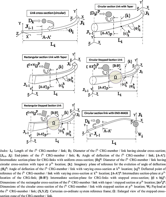
Figure 11.22. Schematics of the deflection hue of five representative compliant members of the CRG.
Download figure:
Standard image High-resolution imageIt may be stated here that alongwith payload, damping of the ensemble CRG-system also comes into play and the same becomes instrumental in deciding the attenuation of vibration within a finite time-range. Besides, spring stiffness factor influences the ensemble dynamic model of the CRG-system, which, in turn, is dependent upon the deflection hue of the CRG-members/links.
With this preamble, we will postulate the fundamental equation of control dynamics of the CRG, using measurable parameters. As illustrated in figure 11.22, we will treat the CRG-assembly as an open-end cantilever structure, thereby imbibing spring-effects at its links and pin-joints. The ensemble deformation at the CRG-joints will be accounted for as friction torque while stiffness will be estimated through viscous damping of the joints.
If we take a closer look over the traditional dynamic equation of a rotational body involving inertia, damping, stiffness effect and finally torque, then the same can be expanded for CRG too as shown below, which is the fundamental equation of real-time control of any robotic system per se:

Equation (11.44a) is self-explanatory wherein the parameters, 'M', 'B', 'K', 'ϕ' and 'τ' have their natural nomenclatures. For instance, 'M' is the mass moment/inertia of the system; 'B' is the viscous damping; 'K' is the spring constant of the naturally vibrating system; 'ϕ' is the joint angle movement and 'τ' is the torque function. Now, let us take a deeper understanding of this equation and we will observe that it is essentially composed of two broad groups, viz. (a) material-specific equation and (b) torque-specific equation. We can appreciate that equation (11.44a) is in the format of a generalized dynamic equation of motion, namely,

where, 'q' signifies the joint variable in generalized co-ordinates. While the parameters pertaining to the material-specific equation move around the matrices of 'M', 'B' and 'K', the torque-specific equation gives weightage to assimilation of various kinds of torque components appearing in the CRG. We will take an in-depth look into the expanded form of control dynamics equation of the CRG, by amalgamating equations (11.44a) and (11.44b) and inducing a few measurable parameters in subsequent sections.
11.5. Vibration signature of the compliant robotic grippers and compliant wrists
11.5.1. Paradigms of vibration signature
The inherent vibration of CRG and counter-vibration/compression of the CRW are totally built-in type, structure independent and get manifested in two ways, namely: Modal Frequency and Eigen Value. It has been also observed that vibration in CRG is not time-dependent and the duration and periodicity of it cannot be correlated with the task-space of the robotic system. Moreover, this vibration is self-propagating by nature and it gets induced to the successive member of the CRG till the jaw-plate of the gripper. The problem gets more complicated when we attempt for multi-link design of the CRG, wherein various kinds of coupled effect and non-linearity creep in. The tuple of stiffness coefficient and viscous damping of the spring-dashpot-damper model have been expounded in Taylor's series for functional evaluation of the natural frequency of vibration of the CRG and subsequently, modal frequencies. Irrespective of all hardware-types, this inherent vibration of CRGs gets realized in the form of mild to severe trembling of the slender links and/or shaking or twisting of the link-joint interface and inter-spaced joints. Slenderness of the gripper-links plays a very important role in self-generation of this trembling.
Due to all these characteristics, it is very difficult to obtain a generic analytical model for the vibration in CRG. Usual rule-bases for adopting control algorithm for the end applications are also unviable. The asynchronous data fusion, emanating out of CRG is a challenging research paradigm to date, primarily due to the inherent characteristics in quantifying the output response of the system. Real-time assessment of vibration signature in CRG is a pre-requisite for establishing a reliable control system for any real-life application. The vibration signature in CRG gets assessed in real-time through multiple force sensors, spread over its links, body and joints. The formulation, modeling and instrumentation for such deflection measurement are pre-characterized and the same has been achieved with the help of miniature strain gauges and flexi-force sensors, through excitation data of these sensors in real-time.
It is true that under natural condition of joint rotations of the ensemble robotic system, consisting of CRW and CRG, there will be built-in oscillations in the arms of the manipulator as well as end-unit, viz. CRG plus CRW. These oscillations and ensemble trembling of the manipulator arms are not coupled all the time and due to this, we get different deflection hues for the manipulator. There are various pathways to study the patterns of deflection hues and subsequent oscillations of the CRG and CRW, which get translated to robust analytical models for evaluating vibration-related parameters under real-time dynamics. Nonetheless, in its simplest form, we will consider here undamped free vibration of the CRG, without any external forcing. This free vibration model has been selected in order to study the natural pattern of deflection/trembling of the CRG due to its own inherent dynamics, namely, rotation of its links via the servomotor system. This natural oscillation paradigm of CRG is also supplemented with two facets, viz. (a) no external forcing on any of the CRG-member and/or CRW in any form (i.e. condition of 'forced vibration' is excluded) and (b) no viscous damping from exterior of the CRG and/or CRW (i.e. condition of 'viscous damping' is excluded). Our study, experimental investigation and finally, numerical assessment of natural frequency of vibration of the CRG–CRW tuple is based on this basic paradigm of undamped free natural vibration.
11.5.2. Development of spring-induced geometric models
It is customary to adhere to a traditional 'spring model' to designate free vibration of the CRG-members and/or CRW-system. However, criticalities in vibration signature will eventually emerge due to several natural causes, thereby producing varying amplitude-frequency of the induced vibration in different members of the CRG. This is a very obvious process and it is system-generated. However, the problem of induced vibration is comparatively less in CRW, because of its end-connections. Nonetheless, the challenge lies with accurate and effective modeling of this varying vibration using the spring model. We will discuss here the intricacies of the vibration model using the novel pathway of designing various innovative layouts for these spring elements. It may be noted that the said layout schemes for the spring elements are segregated on the basis of modeling for the CRG or CRW, namely: (i) individual component-level; (ii) sub-assembly level: concept of equivalent spring; and (iii) system assembly-level. These three ordered levels of modeling will be detailed in the following three sub-sections, respectively.
11.5.2.1. Layout schemes for the spring elements
The physical parameter of a spring that goes instrumental in characterizing its performance, i.e. its elongation and subsequently natural pathway of oscillation in vertical plane, is nothing but its stiffness matrix. In uni-axial deformation model of the spring, this stiffness matrix is analogous to spring constant 'K', having dimension: MT−2 (force per unit length). As all other parameters of the CRG-members and that of CRW-system are essentially material-specific or design-specific, it is the value of 'K' that controls the numerical value of the natural frequency of vibration. However, the value of 'K' is the effective value, which is to be obtained through various combinations of placement of the spring(s) in the model. Further, the value of 'K' may not be equal in all such combinations; and, we may use non-identical springs with different values of the spring constant. In a nutshell, the design of the spring elements is a vital aspect of the design ensemble of the CRG as well as CRW. In fact, there can be various design-architectures of the spring elements/members that are feasible from the point-of-view of manufacturing. These are essentially out-of-the-box solutions for the spring layout of CRG and CRW, which will be mounted directly over the link/member of the CRG and/or CRW in the model. Figure 11.23 schematically demonstrates ten novel layouts for the spring elements that can be used as feasible and realizable options to model in situ vibration in the specific members of CRG or CRW. The physical disposition of the representative member of CRG or CRW may be noted along with the interfacing of pair(s) of strain gauges, as part of sensory instrumentation.
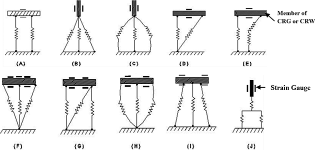
Figure 11.23. Schematics of feasible layouts of spring elements symbolizing in situ vibration of CRG-member/CRW.
Download figure:
Standard image High-resolution imageTwo types of design layouts of springs are emerging so far as the original disposition of the member of CRG or CRW is concerned, as per the schematic of figure 11.23 above. These are: (a) Type-I: horizontal member: spring-mounted (design schemes: 'A', 'D', 'E', 'F', 'G', 'H', 'I') and (b) Type-II: vertical member: spring-mounted (design schemes: 'B', 'C', 'J'). It is to be noted that irrespective of the type of layout, spring-members are acting in one direction only in order to characterize the vibration pathway. In other words, spring rheology (tension and/or compression) is based on uni-directional arrangement. It is to be noted here that design options for vertical/column members are limited, as the layout of the springs will not undergo major variations. However, horizontal members of CRG or CRW will have a number of variations possible, owing to the layout of the spring member(s). Another interesting feature of this spring mounted modeling structure is augmentation of a couple of 'branches' (just like 'tree branches') of the different spring elements and/or spring- dashpot system, in extended layout. The fundamental aspect of the disposition of the spring metric for horizontal members is essentially multi-spring type, which is the crux of the spanning layouts (refer to 'A', 'D', 'E', 'F', 'G', 'H' & 'I' of figure 11.23). As a matter of fact, multiple springs give rise to options for enhanced compliance in the overall structural geometry of CRG or CRW. Moreover, with various permutations of spring-layout, flexibility of modeling of the overall CRG/CRW-structure gets boosted. Nonetheless, individuality of the spring-elements, irrespective of the members (horizontal or vertical) thereof is always maintained. It may be noted here that all spring-elements in the layouts of figure 11.23 are straight and not bonded with any fellow spring. In contrast to this, we will now deal with another layout, wherein disposition of the spring-elements can be functionally bonded and/or crisscrossed with fellow spring-element(s). Figure 11.24 schematically illustrates these layouts.

Figure 11.24. Schematics of functionally bonded spring elements under in situ vibration of CRG-member/CRW.
Download figure:
Standard image High-resolution imageIt may be noted that crisscrossed layout of the spring elements is a unique call of design, wherein two spring-members are 'crossing' each other to form an ensemble. These layouts are entrusted to provide more subtle input to the characterization of real-time damping of the CRG-member as well as CRW. Let us now investigate two other types of design layouts under in situ vibration-based layout, viz. 'circular member: spring-mounted' and 'elliptical member: spring mounted', as illustrated schematically in figure 11.25.
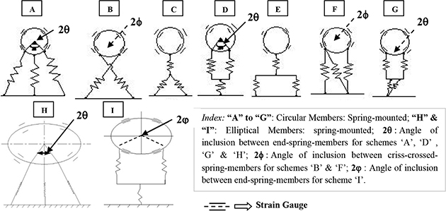
Figure 11.25. Disposition schematics of circular and elliptical spring elements under in situ vibration of CRG-member/CRW.
Download figure:
Standard image High-resolution imageThe layouts of the spring elements, shown in figures 11.23 to 11.25, are the essential pre-requisites for the subsequent modeling. Mathematical paradigms of the layouts of these spring elements need to be ascertained a priori to capture the characteristics of the free undamped vibration of the CRG-members and/or CRW-system.
11.5.2.2. Schematic dispositions of equivalent spring element
The spring-based geometric layouts of an individual member of CRG and/or CRW with strain gauge instrumentation, as explained in the previous sub-section need system-level culmination so as to subsume in the vibration model for the robotic grasp. Accordingly, ensemble vibration (for CRG) and damping/counter-vibration (for CRW) have to be modulated through the concept of Equivalent Spring Element (ESE). The characteristics of ESE will be wholesome and intrinsic so as to represent the ensemble CRG or CRW effectively under run-time condition. It is thus noteworthy to highlight various possible combinations of ESE, which can be conceptualized as extended manifestation of series and parallel layout. Figure 11.26 illustrates schematic disposition of the undamped free natural vibration scheme of CRG or CRW in sub-assembly mode, along with ten possible layouts of ESE thereof (refer to # I to X). It may be stated that standard formulae of the series-parallel combinations will be used to compute ensemble spring constant, considering equal values of 'K' in all these 10 layouts. Numerical treatment will remain the same in cases where multiple different springs with unequal values of 'K', say K1, K2, K3,...etc are used in the model.
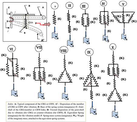
Figure 11.26. Schematic disposition of undamped free natural vibration schemes of equivalent spring element.
Download figure:
Standard image High-resolution imageWe know that numerically, natural frequency of vibration is a function of 'K' and 'mass' of the vibrating member, as per the postulation of natural vibration. As there is no alteration in the 'mass' ('m') of the vibrating member, sole dependency of natural frequency of vibration (fn ) will be on the 'equivalent spring constant' (Keq ) of the CRG-member or CRW-link system. This proposition justifies the lemma of figure 11.26 with its 10 different models of spring layout. This direct proportional relationship between 'fn 'and 'Keq ' is the crux of the engineering aspect of the study of the undamped free vibration of CRW-link(s) and CRG-members. Thus, it essentially boils down to the near-optimal numerical evaluation of 'Keq ' using the known parameters of CRG or CRW.
It is interesting to observe the dispositions of the spring-elements in the layout of figure 11.26 and to be specific, the gradual variation of complexity of the layouts. By default, the first layout is the simplest with only one spring-element, having spring-constant 'K'. The next two schemata, viz. layouts #2 and 3 represent series and parallel combination of spring-elements in simplest form. Layouts #4 and 5 involve three spring-elements each, disposed in two geometrical variants. Two extended versions of layout #4 are depicted in the next two schemata, namely, layouts #6 and 7. The complexity of the computation of 'Keq ' begins from layout #6 and continues thereafter. We introduce new sub-schemata of 'star-delta connection' of spring-elements in the next three layouts, viz. layouts #8, 9 and 10. While layout #8 shows the basic star-delta type spring-elements, complexity gets introduced in layout #9 with additional spring-elements, adjoining the basic star-delta. The last layout is a Boolean combination of layouts #7 and 8 and it is, by virtue, the representative of all such possible Boolean combinations of layouts of the spring-elements in CRW-link or CRG-members.
11.5.2.3. Development of the spring—structural model
After comprehending the component-level spring layouts followed by layouts for the equivalent spring element, we will move on to detailing of the system assembly-level model of CRW or CRG-system. This modeling is essentially customized type, entitled, 'Spring Structural Model' (SSM). The root of the customized SSM is related to the development of a 'spring structure' for the ensemble, i.e. CRG or CRW, divided into specific numbers of functional sub-assemblies, decided a priori. These functional sub-assemblies are created as virtual entities with ESE, with a goal towards efficient run-time modeling of the control system of CRG or CRW. It is important to have geometric symmetry of the design of the CRG in order to construct the SSM. By virtue of the customized design of two-fingered type CRGs, all prototypes of our CRGs are symmetrical and thus it is relatively easier to construct an SSM for those designs. Nonetheless, the technique can be adopted for asymmetric designs of CRGs as well with proper selection of ESEs. In either of the cases, dynamics-based governing control system equation of the CRG will subsume the effect of each ESE separately with the input of torque-components.
We will illustrate the customized SSM for two representative CRGs, vide PAMRoG (discussed in sub-section 11.2.3.3) and SIMSJRoG (discussed in sub-section 11.2.5.2), each with three functional sub-assemblies with ESEs. Figure 11.27 shows the disposition of SSM for PAMRoG and the same for SIMSJRoG is presented in figure 11.28. The prototypes of the respective CRGs are also included in the figures for easy resemblance of the model with the actual.

Figure 11.27. Spring-structural model of the representative compliant robotic gripper assembly (PAMRoG).
Download figure:
Standard image High-resolution image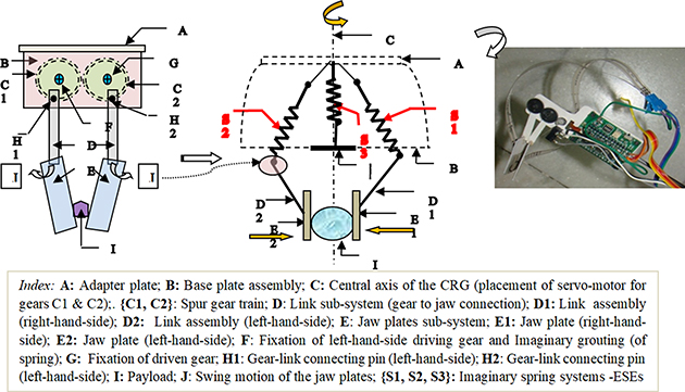
Figure 11.28. Spring-structural model of the representative compliant robotic gripper assembly (SIMSJRoG).
Download figure:
Standard image High-resolution imageAs evident through the illustrated view of SSM in figure 11.27, the backbone of the SSM consists of three ESEs, located symmetrically within the mechanical ensemble of PAMRoG. The form and force closures are ensured through the actuation of the ESEs, as shown in the photographic view of the grasp of a solid cylindrical object.
Although the backbone of SSM for SIMSJRoG consists of three ESEs, as shown in figure 11.28, the link sub-system is different from that of PAMRoG. The ESEs are located symmetrically within the mechanical ensemble of SIMSJRoG. In contrast to the SSM of PAMRoG, we will encounter a special swing motion ('J') of the jaw plates due to the customized design of the jaws. This motion is dependent on the modeling of two ESEs, viz. 'S1' and 'S2'. The link sub-system ('D') has greater significance here as direct transmission of motion in being made as an outcome of the excitations of the ESEs.
It may be stated here that the complementary aspect of the SSM is sensory instrumentation that works as a measured for real-life experimentation towards evaluation of the in situ vibration of the CRG-system. The real-life design model for the in situ vibration of the CRG involves requisite sensory sub-systems for the measurement of strain in the CRG-members. Hence, direct ramification of vibration model of CRG is the sensor-based SSM. Figure 11.29 schematically illustrates the design of a sensor-based SSM for the enhanced design model for CRG and/or CRW.
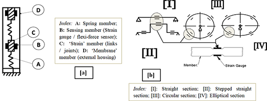
Figure 11.29. Sensor-instrumented spring-structural model of CRG or CRW: (a) basic architecture; (b) strain gauge layout.
Download figure:
Standard image High-resolution imageThe basic architecture of the sensor-instrumented SSM of CRG or CRW-system comprises four distinct members, viz. 'A', 'B', C' and 'D', as illustrated in figure 11.29(a). We have shown two successive 'strain' members in figure 11.29(a) so as to highlight the coupling effect between constituent members of the CRG or CRW-system in actual hardware. It is needless to state that 'sensing' member is the most crucial element of the system and its modeling is dependent on the layout of the sensor-cells (e.g. strain gauges), as shown in figure 11.29(b). The paradigm of in situ vibration of members/links of CRG or CRW-system can be symbolized optimally as the real-time deflection of a hollow beam having four representative cross-sections with mounting of strain gauges, as shown in figure 11.29(b). The locations of placement of strain gauges have been marked by '=' symbol in four possible design variations (straight, stepped, circular, elliptical). The fulcrum location of the beam cross-section is denoted by '∆'. As illustrated in figure 11.29(b), the CRG/ CRW-member will have micro-beam and the force sensing mechanism will be based on beam deflection principle. A particular member may have multiple beams embedded in it, each having its own characterization. The placement of those beams inside the CRG/CRW-member is also another technological challenge. Thus, these as-modeled spring-mounted members will act as in situ vibration source for the CRG/CRW-system, which will be helpful in assessing the overall deflection of the system.
11.5.3. Development of spring-supported vibration model
We will now formulate a customized vibration model for the CRG and/or CRW-system using the concept of ESE. The prime-most attribute of this spring-supported vibration model is natural frequency of vibration. Numerical evaluation of natural frequency of vibration is traditional theory-based and for a specific material and known mass of CRG-member or CRW-link, it is directly proportional to the spring constant of ESE, i.e. 'Keq ', depending upon the layout schemata. Interestingly, 'Keq ' is also dependent on geometry of the CRG-member/CRW-link as well as its material. In a way we get a tuple to evaluate natural frequency of vibration, fn , of the CRG/CRW-link system, as shown below:


where, m: mass of the CRG-member or CRW-link; F: in-built force acting on the CRG-member to cause vibration; A: cross-sectional area of the CRG-member or CRW-link; L: length of the CRG-member or CRW-link; Y: Young's modulus of the material of the CRG-member or CRW-link; δ: deflection of the CRG-member or CRW-link (in the direction of in-built forcing function).
Thus, as per theory, the working formula for the numerical evaluation of 'fn ' becomes (using equations (11.45) and (11.46)),

where, D: diameter of the CRW-link or average diameter of the CRG-members and ρ: density of the material of the CRW-link or CRG-member. Other symbols have been nomenclated earlier in equations (11.45) and (11.46). As an off-shoot to the evaluation of fn we can deduce the working formula for the 'force of vibration ('F'), which is essentially a theoretical and imaginary attribute. Since we are not considering the situation of forced vibration here we will only look at the expression for 'F' as a direct function of the average strain obtained (εav ). in the CRW-link(s) or CRG-member(s), as shown below:

Experimental determination of the natural frequency of vibration of the CRW-link(s) and/or CRG-member(s) is crucial. We need to evaluate it with the help of mere strain gauge data. There is no other way out and besides strain gauge data (of dynamic strain), we cannot even arrange any other instrumentation in real-time for such assessment. This is the greatest irony of a CRG or CRW and we have to deal with it so far as estimation of in situ vibration/natural frequency is concerned. The experimental runs are essentially made with the help of activation of the joint servomotors of the CRG in a selected pattern. In that sense, the experimental runs are representative of pesudo-forced vibration of the CRG and counter-vibration for CRW. Although there is no external forcing function acting on the CRG-members, the vibration is being forced into the system by means of rotational motion of the joint motor of CRG and also the joint-motors of the robotic manipulator interfaced with.
To begin with, we will investigate the phenomena of pesudo-forced vibration of the CRG-member(s) under the excitation created by only one servomotor of the manipulator-joint. Here we assume that all joints of the robotic manipulator are identical in all respects hardware-wise and accordingly, all joint-servomotor systems are equally likely. We also have the pre-condition that during the activation of the specific joint-servomotor, the rest of the joint-motors are not actuated and thus, those remain in the then state of angular postures. With this proposition, the computational formula for natural frequency of vibration of the CRG or CRW-system due to the excitation/rotation of the kth. joint-motor of an 'N'-link serial-chain robotic manipulator under this state of pseudo-forced vibration can be deduced from equations (11.45) and (11.46), as described below:
where, fn (k): natural frequency of vibration of the CRG or CRW-system due to excitation of kth joint-motor of the N-link serial-chain robotic manipulator; Keq : equivalent spring constant for the CRG or CRW-system; M: mass of the CRG or CRW-system; Flink_N v : Pesudo force of vibration at the CRG or CRW-system due to excitation of kth joint-motor of the N-link serial-chain robotic manipulator; δk : deflection occurring at the CRG or CRW-system due to excitation of kth joint-motor of the N-link serial-chain robotic manipulator; εAv (k).: average strain obtained at the CRG or CRW-system due to excitation of kth joint-motor of the N-link serial-chain robotic manipulator; LCRG/CRW : length of the CRG or CRW-system; ρ: density of the material of fabrication of the CRG or CRW-system; ACRG/CRW: Cross-sectional area of the CRG or CRW-system; τmotor (k): run-time torque of the kth servo-motor of the robotic manipulator (∀k = 1,2,...N).
It may be observed that equation (11.49) is the generic format of evaluation of the run-time natural frequency of vibration of the CRG or CRW-system when fitted with a multi-jointed robotic manipulator. Here we are considering the situation wherein only one servomotor of the robotic manipulator is being activated to create the pesudo forced vibration scenario. Hence, source of the vibration, so generated, is the excitation of the system due to the activation of any one of the revolute joints of the robotic manipulator. The very servomotor is responsible for the actuation of the corresponding revolute joint of the manipulator. However, choice of a particular servomotor that is to be activated alongwith its extent of activation (joint movement in degrees) is user-selectable. During this programmed activation, the rest of the servomotors are kept under non-activation mode. It is to be noted here that equation (11.49) is valid if we do not consider any retarding torque due to the joint rotation of the preceding link(s) of the manipulator. The formulation will alter under a real-life situation wherein the pseudo-forced vibration takes into account impedance of the joint that is being actuated by the servomotor. This joint impedance results in a retardation torque and its numerical extent gets defined by a factor, named as 'joint retardation coefficient'. The effect of the joint retardation will be on the preceding link(s) of the robotic manipulator, with respect to the joint-servomotor that is being activated. The revised formula for the evaluation of natural frequency of vibration of the CRG/CRW-system under this real-life situation of joint-retardation is stated below:

where, fn* (k): real-life natural frequency of vibration of the CRG or CRW-system due to excitation of kth joint-motor of the N-link serial-chain robotic manipulator under joint-retardation effect; εAv (k): average strain obtained at the CRG or CRW-system due to excitation of kth joint-motor of the N-link serial-chain robotic manipulator; L : length of CRG or CRW-system; ρ : density of the material of fabrication of the CRG or CRW-system; A: cross-sectional area of CRG or CRW-system; τmotor (k): Run-time torque of the kth servo-motor of the robotic manipulator (∀k = 1,2,...N); λ: Joint Retardation Coefficient (JRC), 0< λ⩽0⊡1.
The syntax of the natural frequency of vibration under a pesudo-forced vibration situation gets computationally complex if two or more servomotors of the robotic manipulator are in simultaneous activation. In such cases, the effective force of vibration on the CRG or CRW-system will be multi-sourced and evaluation has to be made accordingly, keeping the basic format of equation (11.50) intact.
11.5.4. Modeling paradigms and control dynamics for secondary-stage vibration
11.5.4.1. An insight into secondary-stage vibration
The nucleus of run-time control dynamics of CRG as well as CRW-system is the built-in vibration and its incarnations. However, the ground-level vibration gets created inside the envelope of the CRG or CRW-system by virtue of the slenderness of the design. This vibration is primarily deducible through the spring-structural model and formulation, as described in the previous section. But the run-time nature of this nascent vibration gets multiplied as soon as the CRG-plus-CRW-system gets integrated with the robotic manipulator. The synergistic effect of this interfacing results in a higher level of vibration along with its modal frequencies. This vibration is termed as 'secondary-stage vibration' and it has multiple pathways of realization. In fact, the secondary-stage inherent vibration of the robotic manipulator, integrated with CRW and CRG-systems, is directly proportional to the number of degrees-of-freedom of the manipulator. In all practical situations of serial-chain robotic manipulator with CRG, this secondary-stage vibration is evaluated in terms of natural frequency of vibration (ωn ) and the higher-order modal frequencies. On the other hand, the dynamic strain vector (εi , ∀i = 1,2,3,...,k: where 'k' is the link-number of the manipulator) is evaluated from structural analysis of the robotic manipulator. Thus, the paradigm of control dynamics of an integrated CRG plus CRW-system in real-time essentially involves investigation of strain vis-à-vis vibration tuple. In the case of 'direct-to-joint-drive' serial-chain robotic manipulator, the instantaneous real-time displacement will be prudent in the links in the form of 'deflection'.
Hence we can say that the material-specific deformation of any constituent member of the robotic manipulator at any time-instant is a combined effect of natural frequency of vibration and total strain produced inside the said member. The principal axis of such deformation and/or deflection is curvilinear. It may be noted that modal frequency distribution pattern in the robotic manipulator and/or CRG-system can be obtained through FE simulation as well as experimentation, up to tenth mode separately for each member, with a distinct flavor of 'deflection hue'.
The multi-modal nature of the secondary-stage vibration of the robotic system (manipulator plus CRG) needs subtle mathematical modeling, over and above sensor-instrumented SSM. The spring-damper-dashpot design scheme for the link and joint of CRG or CRW-system is the most optimal tool for the said secondary-level vibration analysis as well as real-time vibration control issues. The spring-damper system is self-compensated and the resultant vibration, generated thereof, will be the optimal amount required for stimulating the manipulator-ensemble. The design model of this enhanced sensor-instrumented SSM of the CRG or CRW-system is schematically shown in figure 11.30.

Figure 11.30. Real-life sensor-augmented vibration model of CRG or CRW: (a) design architecture; (b) strain gauge layout.
Download figure:
Standard image High-resolution imageAs shown in figure 11.30(a), CRG or CRW-body will have member(s) mounted on mechanical springs, in order to realize spring-dashpot-based modeling. The design architecture of the real-life sensor-augmented SSM of CRG or CRW-system towards enhancement of pick-up of secondary-stage vibration consists of four distinct members, viz. 'A', 'B', C' and 'D', as illustrated in figure 11.30(a). Like the earlier disposition (refer to figure 11.29(a), two successive 'strain' members are shown in figure 11.30(a) as well so as to highlight the coupling effect between constituent members of the CRG or CRW-system in actual hardware. In this model too, 'sensing' member is the most crucial element of the system and its modeling is dependent on the layout of the sensor-cells (e.g. strain gauges), as shown in figure 11.30(b). The paradigm of the in situ secondary-stage vibration of members/links of CRG or CRW-system can be symbolized optimally as the real-time deflection of a cantilever beam having five representative cross-sections with mounting of strain gauges, as shown in figure 11.30(b). Cantilever-type CRG/CRW-members do possess easy potential for affixing sensing element(s) as well as better relief at the non-fixed end. The locations of placement of strain gauges have been marked by an '=' symbol in the figure, in five possible design variations, viz. straight, stepped straight, curvilinear, curve-straight and straight-semicircular.
As evident from figure 11.30(a), 'A' and 'D' have mutual sharing of kinetics, while the effect of that will be arrested by 'B' and 'C'. This conjugate spring-damper-dashpot model is the key to the assessment of the modal frequencies (1st to Nth mode). It is important to note that an efficient dynamic model of CRG or CRW-system will be able to characterize deformation and deflection of its members and/or sub-assemblies in real-time. While links of CRG and/or CRW are more prone to deflection with certain frequency of vibration, the joints are subjected to mild deformation. At times these two entities are quite unseparable and we need to rely on FEA simulation and trial run of the hardware only. In most of the designs of CRGs that we have explored as well as manufactured, the instantaneous real-time displacement, in the form of 'deflection', was observed to be prudent in the CRG-links. Nonetheless, we can arrive at the following summary on the effect of secondary-stage vibration of CRG/CRW-system, as per table 11.2 below.
Table 11.2. Nature of modal frequencies of secondary-stage vibration in CRG/CRW-system.
| Type | Nomenclature of vibration mode | Observation and remarks |
|---|---|---|
| I | 1st mode | Basic natural frequency of vibration (ωn ) |
| II | 2nd and 3rd mode | Gradual increase of ωn |
| III | 4th and 5th mode | Progressive gradual increase of ωn |
| IV | 6th, 7th and 8th mode | Threshold of failure → higher stress → deformation pattern is like 'deflection hue' in FEA simulation |
| V | 9th and 10th mode | Sharp increase of ωn → failure/undesirable condition |
Before detailing the modeling scheme, we need to take a closer look at the characteristics of a CRG/ CRW-member when subjected to in situ vibration (both inherent as well as external). This phenomenon has been simulated through the actuation of various spring-elements (for in situ vibration) and spring-dashpot elements (for secondary-stage/external vibration) in unison, which are attached to the CRG/ CRW-member.
11.5.5. Modeling force-displacement tuple
The multi-dimensionality of the secondary-stage in situ vibration of the CRG/CRW-system and/or the ensemble robotic manipulator system needs subtle mathematical modeling. As stated earlier, the spring-damper-dashpot design scheme is the most optimal tool for the vibration analysis of CRG/CRW-system as it has inherent uncertainties and real time vibration control issues. Since this design is related to 'forcing function' of spring system or spring-mass-damper system, we have enough room to imbibe the concept of interval mathematics to model and solve the force displacement tuple. As a matter of fact, this in situ vibration-based method has become prudent in design synthesis for CRG/CRW due to its in-built nature of the range of dimension of the parameters. We will explore the said postulation of vibration-based design method, with reference to the schematics of figure 11.30(a).
We have for each design variable, 'X' in 'ℜ' ('ℜ': 3D space in real-time), a close association of parametric range (end-values) such that {X}: → [Xmin, Xmax ] in 'ℜ'. These two range-values of 'X' will be experimentally determined and/or simulated a priori. Thus, we will have a combination of four design variables, pertaining to 'A', 'B', 'C' and 'D' (as per the Real-time Spring-Damper-Dashpot Design Model for in situ Vibration of CRG/ CRW-system).
'A':→ {Spring-Constant} →{K}: → [Kmin,
Kmax
]
 ℜ
ℜ
'B'→ {Strain Gauge Resistance & Gauge Length} →
 →
→ ![$[\begin{array}{ll}\underline{R} & \bar{R}\\ \underline{L} & \bar{R}\end{array}]$](https://content.cld.iop.org/books/10__1088_978-0-7503-3483-9/revision4/bk978-0-7503-3483-9ch11ieqn66.gif) →
→ ![$[\begin{array}{ll}{R}_{SG{\rm{\min }}} & {R}_{SG{\rm{\max }}}\\ {L}_{G{\rm{\min }}} & {L}_{G{\rm{\max }}}\end{array}]$](https://content.cld.iop.org/books/10__1088_978-0-7503-3483-9/revision4/bk978-0-7503-3483-9ch11ieqn67.gif)
 ℜ
ℜ
'C'→ {Member Length and Member Width } →
 : →
: → ![$[\begin{array}{ll}\underline{l} & \bar{l}\\ \underline{w} & \bar{w}\end{array}]$](https://content.cld.iop.org/books/10__1088_978-0-7503-3483-9/revision4/bk978-0-7503-3483-9ch11ieqn70.gif) →
→ ![$[\begin{array}{ll}{l}_{{\rm{\min }}} & {l}_{{\rm{\max }}}\\ {w}_{{\rm{\min }}} & {w}_{{\rm{\max }}}\end{array}]$](https://content.cld.iop.org/books/10__1088_978-0-7503-3483-9/revision4/bk978-0-7503-3483-9ch11ieqn71.gif)

'D' → {Joint Strength: Membrane} → {JM
}:
→
![$\left[\begin{array}{ccc}\underline{{J}_{M}} & , & {\bar{J}}_{M}\end{array}\right]\,\left[\begin{array}{ccc}{J}_{{M}_{\min }} & , & {J}_{{M}_{\max }}\end{array}\right]\,\in {\boldsymbol{\Re }}$](https://content.cld.iop.org/books/10__1088_978-0-7503-3483-9/revision4/bk978-0-7503-3483-9ch11ieqn73.gif)
The formulation and computation of these interval matrices are crucial for the calibration of the sensing elements of the CRG or CRW-system. Now, while dealing with a group of design variables like in this case of A', 'B', 'C' and 'D' (i.e. four variables) or in expanded fashion six variables [K, l, w, RSG , LG , JM ] we can define 'Constraint Satisfaction Problem' (CSP). By definition, CSP is formulated by a set of variables, {V}= {x1, x2,.... xn } along with a set of 'Constraints' or equations, {E} = {c1, c2,...... cn } over interval domains, {[x1] [x2] ..... [xn ]}. The formulation of CSP is essentially design-specific, i.e. for a particular design of the CRG/CRW-member we will have one CSP formulated. Hence, each CSP can tackle a group of new variables, pertaining to the tuple of {V} and {E}. A damping model can be established mathematically using this lemma.
11.5.6. Modeling of real-time control dynamics
With this preamble, we will postulate the fundamental equation of control dynamics of the CRG/ CRW-system, using measurable parameters. We will treat the CRG/ CRW-system as an open-end cantilever structure, thereby imbibing spring-effects at the links and joints. The ensemble deformation at the CRG/CRW-joints will be accounted for as friction torque while stiffness will be estimated through viscous damping of the joints. The root of this model is with the SSM (refer to sub-section 11.5.2.3) of the representative CRGs with three functional sub-assemblies, as illustrated in figure 11.31 below.

Figure 11.31. Spring—structural model of the representative CRG with functional sub-assemblies.
Download figure:
Standard image High-resolution imageWe will analyze the schematic disposition of figure 11.31 from the viewpoint of control system layout of CRG/CRW-system. To begin with, let us take an in-depth look into the expanded form of the control dynamics equation of the CRG/ CRW-system, viz. equation (11.44), by amalgamating both parts of the equation and inducing a few measurable parameters. The following generic equation is arrived at in support of the real-time dynamics of the CRG/CRW-system under the influence of secondary-stage vibration (based on the SSM):

where, i: CRG sub-assembly number; p: joint index (CRG-II and CRG-III in this case); {Ji , Ji+1, Ji+2}: consecutive 'pin' joints of the CRG-I,II,III (in this case); θ: rotation of the link/spring of the CRG-sub-assembly; M: desired moment of inertia matrix of the CRG-sub-assembly; B: desired viscous damping (friction) coefficient of the CRG-sub-assembly; Kp : desired stiffness of the 'pin'-joint; Ki : Desired stiffness of the CRG-sub-assembly; δ: initial angular position of the CRG-sub-assembly and/or 'pin'-joint; τf: frictional torque; τL : load torque; N: real numbers ('I', 'II', 'III').
As a finer assessment of the control dynamics of the CRG/CRW-system, viscous damping will also be modeled as two metrics, located at CRG-sub-assembly and at 'pin'-joints. This conjugate approach of modeling the spring constant and viscous damping has been used in order to ascertain the intricacies of the real-life actuation of the CRG. The ensemble deformation at the CRG-joints will be accounted for as friction torque while stiffness will be estimated through viscous damping of the joints as per the equation below in support of the real-time dynamics of the CRG:
where, i: CRG-sub-assembly number; p: joint index (CRG-II & CRG-III in this case); {Ji, Ji+1, Ji+2}: consecutive 'pin' joints of CRG-I,II,III (in this case) ; θ: rotation of the link/spring of the CRG-sub-assembly; M: desired moment of inertia matrix of the CRG-sub-assembly; Bi : desired viscous damping (friction)coefficient of the ith CRG-sub-assembly; Bp : desired viscous damping coefficient of the pth 'pin' joint of the CRG-sub-assembly; Kp : desired stiffness of the pth 'pin' joint; Ki : desired stiffness of the ith CRG-sub-assembly; Kip : Desired stiffness of the CRG-sub-assembly-joint interface (ith sub-assembly and pth joint in mating condition); δ: initial angular position of the CRG-sub-assembly and/or 'pin' joint; τf: frictional torque; τL : load torque; N: real numbers ('I', 'II', 'III').
It may be observed that the control dynamic model of the CRG, as stipulated above, is essentially a torque-induced material equation, wherein selection of appropriate material for the CRG-sub-assemblies (especially the links as well as the joints) is very crucial. The terms of the dynamic model equation includes vectors of angular velocity and angular acceleration that need to be determined through real-time experiments. The so-called tiny flexible link of the CRG and/or CRW can be conceptualized as a 'free elastic body' in an ideal scenario, but in all practical purposes we can treat it as a 'cantilevered elastic body' (because of the motor overhung), which acts as the prime source of in situ vibration of the CRG and/or CRW. The secondary-stage vibration of CRG/CRW-system is evaluated in terms of natural frequency of vibration (wn ) and the higher-order modal frequencies.
We may note that in situ secondary-stage vibration of CRG or CRW or the entire robotic manipulator is directly proportional to its number of degrees-of-freedom. The study on the movement/instantaneous motion of CRG-links should ideally be restricted to low joint speeds, thereby neglecting the second-order effects of elastic deformation. In fact, in all such cases, second order and higher terms of control equation need to be avoided for successful control of the CRG. On the other hand, the dynamic strain vector (ei , ∀i = I,II,III,...,k: where 'k' is the sub-assembly-number of the CRG) is evaluated from structural analysis of the CRG. Thus, the paradigm of control dynamics of CRG in real-time essentially involves investigation of strain vis-à-vis vibration tuple.
We have bestowed importance to the characteristics of viscous damping and spring constant by augmenting influence of both link and joint and finally, the link–joint interface of the CRG/CRW-system. Accordingly, we can model viscous damping coefficient of joint and stiffness of link-joint interfaces of the CRG/CRW-system as:

In contrast to earlier control dynamics equation, we may deduce the generalized expression for the torque-specific equation for the CRG/ CRW-system as:

where 'F' denotes the real-time function of 'q' and time-instant 't', which is obtainable from the generalized terms of the control dynamics equations. Thus we can express F(q,t) for any CRG/CRW-sub-assembly as per the following expression, utilizing material-specific nomenclature of the CRG (viz. 'α', 'β', 'λ'):

The spring-damper (dashpot)-based control dynamics model (refer to equations (11.51) and (11.52)) will be self-compensated in nature and the resultant vibration, generated thereof, will be the optimal amount required for stimulating the CRG/ CRW-ensemble. In fact, disposition of a specific CRG/ CRW-member under in situ as well as secondary-stage vibration can have several incarnations so far as the damping model for the control system is concerned.
It may be concluded that the overall design architecture of CRG/CRW-system will have a decent deflection scheme: the first is the inherent deflection/vibration of itself and the second one is the deflection of the links and joints of the associated robotic manipulator. This conjugate deflection paradigm is the crux of the controller design of the CRG or CRW-system in real-time.
11.6. Development of turning model for vibration synthesis of compliant robotic gripper and wrist system
11.6.1. Facets of vibration synthesis
At this point it is worth mentioning that a complete dynamic model of the serial-chain robotic manipulator, integrated with CRW plus CRG-system must incorporate both link and joint rotation as well as joint twist. While the paradigm of real-time rotation of link and/or joint of CRG/CRW-system will be tackled by the control dynamics model delineated hitherto, vide equations (11.52)–(11.55), modeling of joint twist will call for in-depth analysis of the twisting phenomena, comprising twist of the joint and twist at the link–joint interface. Twist of the links and joints of CRG/ CRW-system is complex and it will involve modeling of the stiffness in quadrature plane(s) at a particular time-instant. It may be noted that the root–control system model, vide equations (11.54) and (11.55) do not involve time function and thus the model is perfectly suited for joint flexure only.
The real-time dynamics of the joints of the CRG will comprise three independent phenomena, namely: (a) twist; (b) turn; and (c) angular displacement. Out of these three facets, 'turning of joints' is the most significant in the case of CRG. Likewise, turning phenomenon is significant for the CRW too. It may be noted that the turning of CRG and/or CRW-system is manifested essentially at the local frame of references and these phenomena differ from the turning/twisting of joints of the serial-chain robotic manipulator, integrated with a combined CRG system. It is to be noted that 'joint twist' phenomenon is not significant in the case of CRG as the majority of the twisting torque will be absorbed by the wrist of the CRG, i.e. essentially the CRW-system. On the other hand, 'joint turn' will be somewhat significant; and, it will be realized through 'turning of the jaws' of CRG or links associated with the jaws. We will now go through the analytical modeling of the turning phenomena of the CRG and/or CRW-system, as obtainable in real-time conditions.
11.6.2. Formulation of the turning model
We may note that joint dynamics of the CRG-system and/or CRW play an important role in defining the 'impedance' at the link–joint interfaces. These impedances are intra-joint type and get activated as and when the joint of the CRG is in motion. This joint impedance of turning phenomenon of CRG can be modeled as:

where, Itu_CRG: impedance of turning of the CRG-joint; VCRG: volume of the 'turned' segment(s) of the CRG; ρCRG: average value of the density of the CRG-material(s); τtu_CRG: turning torque of the CRG; λCRG: dissipation factor. It may be noted that although equation (11.56) is indexed for CRG, it is valid for CRW as well, as the formulation has been made using basic principles of enegy and mass balance.
However, since the CRG is fabricated from different components and sub-assemblies having various kinds of materials, all segments of the CRG are not identical. Hence, volume of the 'turned' segment(s) of the CRG can be estimated analytically by the cumulative sum of 'j' number of segments (j = 1,..,p):

Now, theoretically, each of these 'j' number of 'turned' segments inside the physical enclosure of the CRG and/or CRW-system will undergo small-scale turning and the torque, responsible for those small-scale turning can also be estimated. The ensemble 'turning torque' of the CRG can be evaluated as:

where, (Ftu_CRG)k : force responsible for the turning phenomenon of the kth segment of the CRG and (rCRG)k : radius of turning (imaginary) of the kth segment of the CRG. We assume all of these elemental forces for turning, i.e. Ftu_CRG are co-planar and hence the 'moments', so generated at each of the k-segments (k = 1,...p) can be added in order to evaluate the ensemble turning torque. We can obtain angular torque of turning as well, by adhering to a different procedure. As angular torque will be intermixing in nature and it will span evenly between the segments, we will use infinitesimal angular torques for the evalaution of the ensemble. In other words, we won't go by the segmental distribution of the masses of the CRG, unlike the case of the estimation of the linear turning torque. The ensemble angular torque of turning will be estimated within the thresholds of the angular velocity of the CRG-system. The formulation is shown below:

where, τtu_CRG∣ang
![]() : angular torque of turning of the CRG; ICRG: moment of inertia of the CRG; ωCRG: angular velocity of the CRG-system; dωCRG: infinitesimal angular velocity of the CRG.
: angular torque of turning of the CRG; ICRG: moment of inertia of the CRG; ωCRG: angular velocity of the CRG-system; dωCRG: infinitesimal angular velocity of the CRG.
The theoretical formulation of the turning torque of the CRG, vide equations (11.58) and (11.59), will be just sufficient to have an overall estimation of the power requirement of the servomotor of the CRG or prime-movers for the CRW-system. However, the actual evlaution of the turning toque needs to be made with the help of experimentation in real-time grasp of payload. This real-life evalation of turning torque will be dependent on the design features of the CRG as well as the disposition of the SSM. In other words, such real-life evaluation will be made with respect to strain gague-based sensory instrumentation of the CRG/CRW-system. The final form of the said indigenously-developed impedance model of the CRG, based on the SSM of figure 11.31 as well as experimental evaluation of turning torque will be:

where, τtu_CRG(t): total torque of turning of the CRG at tth time-instant; Kbp_CRG(t): effective spring-constant of the base plate sub-assembly of the CRG at tth time-instant as per spring-structural model; Kll_CRG(t): effective spring-constant of the left link sub-assembly of the CRG at tth time-instant as per spring-structural model; Krl_CRG(t): effective spring-constant of the right link sub-assembly of the CRG at tth time-instant as per spring-structural model; θ0: initial angular position of the CRG system; θbp_CRG: intermediate angular position of the base plate sub-assembly of the CRG at tth time-instant; θll_CRG: intermediate angular position of the left link sub-assembly of the CRG at tth time-instant; θrl_CRG: intermediate angular position of the right link sub-assembly of the CRG at tth time-instant. It is crucial to have proper experimental validation of the turning torque of the CRG/CRW-system as per the model of equation (11.60) in a repeated manner.
11.6.3. Accumulation of vibration in robotic wrist
It is important to note here that a sizeable portion of the ensemble turning torque of the CRG gets accumulated inside the housing of CRW during grasp operation so as to give enough resilience to the CRG for beter form and force closure. In fact, this accumulation of run-time vibration will go beyond the physical structure of CRW and eventually, it will reach the robotic manipulator that is being interfaced with the CRG-plus-CRW-system. This accumulation process will lead to generation of counter-vibration in CRW and it will help harnessing the trembling of the CRG during the grasp. The overall forcing function of this couner-vibration will be compresive type, by and large. Interestingly, this compresive type forcing function, responsible for generating counter-vibration will be highy time-dependent and it will act only for a specific duration of the grasp in order to ensure slip-free force closure. Thus, activation protocol of the counter-vibration of CRW is analogous to spring-dashpot-damper system of the spring-structural model (of the CRG). In other words, occurrence of counter-vibration in CRW will be realized via a suitable deflection model, aided by: (i) spring member (ESE) and (ii) spring-dashpot-damper member. With reference to the layout of figure 11.31, we can extend the paradigm of compressive forcing function of CRW analytically as shown below:

where, x: displacement of the CRW-members under the influence of compressive forcing function; M: mass of the CRW-system; B: viscous damping coefficient of CRW-system as cyclic function of time-instant, 't'; K: eqivalent spring constant of CRW-system as cyclic function of time-instant; FC (t): Compressive force function at tth time-instant. It may be noted that we have modeled both 'B' and 'K' as cyclic functions that are differentiable on a continuous time-spectrum. Further, by principle, both 'B' and 'K' should be function of 't' according to the energy disipation theory of viscoelastic dampers. This is a deviation from our earlier postulations, namely, equations (11.51), (11.52), (11.54), (11.55) and (11.60), wherein dynamic models of CRG/CRW-system have been developed by considering angluar shift of the gripper assembly. The aspect of differentiability on a continuous time-scale engulfing the entire grasping process by the CRG has propelled us to think of suitable continuous functions for 'B' and 'K' from an analytical angle. Accordingly, we have zeroed on sine and cosine functions for 'B' and 'K', respectively, which culminates in the following governing equation for the vibration accumulation at CRW, viz.:
We may note that sensory instrumentation plays a big role in the assessment of the counter-vibration of CRW-system in real-time. It is also important to study the change of value of FC (t), numerically during the entire time-stamping of the grasp. Hence, a re-arranged form of equation (11.62) will be the useful disposition of the evaluation the ensemble compressive force of the CRW-system, as detailed below:
Thus, equation (11.63) is expounded in functional form of 't', wherein positive-signed terms and negative-signed terms will appear for any two consecutive terms together. Naturally, equation (11.63) is the practical form of the control dynamics of CRW-system, prior to fitting experimental data.
11.7. Case-studies and experimental results
11.7.1. Robotic system used for the case-study
In order to maintain good parity in size as well as external disposition, we have used a small-sized table-top robotic manipulator as the case-study. This indigenously developed robotic system is semi-flexible type, having low tare-weight. The beauty of this semi-flexible table-top robotic system lies in its quick adaptability to a variety of CRG, especially, our indigenous designs. The curvilinear-jaw type CRGs are ideally suited for grasping cylindrical or spherical objects, such as bottle, cup, tumbler, ball etc. Accordingly, provision has been made to interface any one of those CRGs (refer to sub-section 2.4) to this Test Robotic System. Figure 11.32 shows the photographic view of the indigenously-developed robotic system, fitted with a curvilinear-jaw CRG.
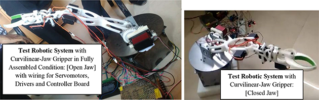
Figure 11.32. Photographic view of the test robotic system fitted with curvilinear-jaw gripper [1], copyright (2020) with permission of Springer.
Download figure:
Standard image High-resolution imageThe Test Robotic System (TRS) has a characteristic design feature that is commensurate to its customized controller. The hardware of the robotic manipulator was accomplished in a way to minimize the inherent shaking of the manipulator arms. Besides, all three variants of the curvilinear-jaw CRGs, augmented with this test robotic system, have been activated with the aim of synchronization of dynamics of the manipulator body. The performance of TRS was ensured after repeated trials in order to control the trembling of links to the best possible extent.
11.7.2. Experimental synopsis
Two posture-driven strategies for control command syntax for the TRS have been formulated as part of the present research, pertaining to two different phases of the slip-free grasp of an object: (a) in-plane grasping and (b) off-plane lifting. As part of in-plane grasping, the second link and the gripper have been kept horizontal and parallel to the ground during the entire course of gripping of the object. In contrast, the second link and first link of the TRS must move through the same angle but in opposite directions for proper off-plane lifting. Figure 11.33(a) illustrates the real-life experimental view of the TRS undergoing in-plane grasping of a cylindrical object, while the real-life experimental view of the off-plane lifting is shown in figure 11.33(b).
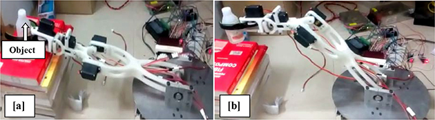
Figure 11.33. Photographic view of: (a) in-plane grasping and (b) off-plane lifting of object by the test robotic system [1], copyright (2020) with permission of Springer.
Download figure:
Standard image High-resolution imageThe paradigms of in-plane grasping of 'nested' task, e.g. shake-free gripping of a glass filled with water, have been achieved by the TRS through dedicated control semantics. Although gripping of glass can be accomplished by a regular control scheme, advanced programming is needed to ensure shake-free gripping so that dripping of water from the glass can be avoided. We have successfully carried out this sort of nested task with the TRS wherein the coupled state vector of the control system has been solved. Similarly, for off-plane lifting, it is being ensured through the customized control semantics that the robotic manipulator is rotated till destination co-ordinates are reached and the robotic system is able to place the object without jerking. The other classical problem of off-plane lifting that has been experimented with is serving/pouring liquid inside a tumbler. In this case, the angle of the robot-wrist gets finalized in order to serve the content without spilling. Figure 11.34 shows the nested experiment of off-plane lifting and sideways-pouring, as performed by the TRS, along with exterior lengths of the links and gripper.

Figure 11.34. Real-time testing of nested work-module by the test robotic system [1], copyright (2020) with permission of Springer.
Download figure:
Standard image High-resolution imageThe selection of rotational speed of the motor of the TRS is equally crucial in all these experiments so as to launch the control system appropriately. In fact, object manipulation has been carried out with a slow speed at the robot-wrist, which is approximately 25% of the base rotation speed (~3–4 rpm). A time delay is imbibed between every incremental angle of rotation so as to ensure jerk-free movement of the wrist and gripper assembly during task execution. The customized program module has been made interactive in order to systemize augmentation of multiple grippers in quick succession. The real-life performance of the TRS with slip-free robust grasp by the CRG can be visualized through the following video-clips at: https://www.youtube.com/watch?v=lpkQ8JM1-rY; https://www.youtube.com/watch?v=E5G_veak8tU; https://www.youtube.com/watch?v=K6OZYSr-8pk.
11.7.3. Sensory instrumentation and test results
We have used strain gauge-based instrumentation all along the TRS, both at manipulator-links as well as at the CRG. The backbone of the instrumentation is realized through National Instruments™-made products, e.g. system chassis, data acquisition card and signal conditioner. This instrumentation has easy handling with the sensor-cells at one end and computer system at the other side for seamless real-time processing of sensory data. The hardware instrumentation has compatibility with a matching software routine, provided by LabView®. Figure 11.35 schematically illustrates the hardware-level layout of the sensory instrumentation for the TRS, alongwith a representative program-module in LabView®.

Figure 11.35. Schematic of the sensory instrumentation of the test robotic system for real-time grasp experimentation.
Download figure:
Standard image High-resolution image
The dynamic strain values were computed based on the readings of the strain gauges. A total of six strain gauges were mounted on the TRS: four on the first link and the remaining two on the second link. Likewise, two strain gauges were affixed on the CRG. The strain values, so obtained, were instrumental in computing the natural frequency of vibration of the CRG and also the same for the TRS-link(s). Table 11.3 presents the ensemble dynamic strain values of 6 nos. strain gauges, as obtained during various time-intervals under different trial-runs of the TRS. The dynamic strain values, generated from the strain gauge readings are indexed as 'S1', 'S2','S3' and 'S4' for the first link and 'S5' and 'S6' for the second link of the TRS. The average of the strain values in these two links are labeled as [Av.ε ]1 and [Av. ε]2 respectively. Likewise, the ensemble dynamic strain values of 2 nos. strain gauges ('S7' and 'S8'), fitted on the CRG-body against various trial-runs of the TRS are computed, alongwith average value of the strain, [Av.ε ]CRG thereof. Table 11.4 presents these strain values for the CRG-unit of the TRS.
Table 11.3. Test results on the computation of dynamic strain for the TRS-links. [♠: actual experimental data = tabulated data × 10−5]
| Trial No. | Strain values for the 1st link of the TRS ♠ | Strain values for the 2nd link of the TRS ♠ | ||||||
|---|---|---|---|---|---|---|---|---|
| S1 | S2 | S3 | S4 | [Av.ε]1 | S5 | S6 | [Av.ε]2 | |
| 1 | 0.0532 | 0.0575 | 0.0548 | 0.0586 | 0.0560 | 0.0134 | 0.0148 | 0.0141 |
| 2 | 0.0546 | 0.0567 | 0.0543 | 0.0578 | 0.0561 | 0.0145 | 0.0145 | 0.0145 |
| 3 | 0.0537 | 0.0534 | 0.0548 | 0.0589 | 0.0552 | 0.0138 | 0.0148 | 0.0143 |
| 4 | 0.0542 | 0.0587 | 0.0539 | 0.0584 | 0.0563 | 0.0137 | 0.0152 | 0.0144 |
| 5 | 0.0563 | 0.0544 | 0.0537 | 0.0583 | 0.0556 | 0.0136 | 0.0146 | 0.0141 |
| 6 | 0.0537 | 0.0564 | 0.0542 | 0.0574 | 0.0554 | 0.0138 | 0.0152 | 0.0145 |
| 7 | 0.0485 | 0.0559 | 0.0545 | 0.0579 | 0.0542 | 0.0165 | 0.0147 | 0.0156 |
| 8 | 0.0539 | 0.0575 | 0.0558 | 0.0576 | 0.0562 | 0.0153 | 0.0139 | 0.0146 |
| 9 | 0.0526 | 0.0548 | 0.0546 | 0.0569 | 0.0547 | 0.0155 | 0.0142 | 0.0148 |
| 10 | 0.0528 | 0.0557 | 0.0534 | 0.0573 | 0.0548 | 0.0157 | 0.0145 | 0.0151 |
The average strain values, so obtained, have an important role to play so far as the evaluation of natural frequency of vibration of the CRG-system and/or TRS are concerned. Fundamentally, these strain values (refer to data of tables 11.3 and 11.4) are used to compute natural frequency of in situ primary vibration of the CRG, as per equations (11.45) and (11.47 ). However, in all practical purposes we will come across some sort of 'pesudo-forced vibration' scenario, because our system under case-study is a conjugate form of robotic system. The excitation of the TRS-ensemble will be effected by the real-time activation of either of its joint-servomotors, namely, motors for rotation of joint 1 or joint 2. The natural frequency of this primary in situ type pesudo-forced vibration can be evaluated through the formulation of equation (11.49), wherein input joint-torque will be in Nm and output natural frequency will be expressed in Hz. Accordingly, experimentation was made to observe the pesudo-forced vibration of the CRG under the excitation of the first joint-servomotor of the TRS. Table 11.5 below reports the evaluated values of the natural frequency of primary in situ pesudo-forced vibration of the CRG, 'fn (1)', against the run-time torque of the first joint-motor of the TRS, 'τ1'.
Table 11.4. Test results on the computation of dynamic strain for the TRS-gripper.
| Strain values ♠ | Trial Number [♠:Actual experimental data = tabulated data × 10−5] | |||||||||
|---|---|---|---|---|---|---|---|---|---|---|
| 1 | 2 | 3 | 4 | 5 | 6 | 7 | 8 | 9 | 10 | |
| S7 | 0.0232 | 0.0234 | 0.0189 | 0.0236 | 0.0245 | 0.0243 | 0.0179 | 0.0157 | 0.0178 | 0.0233 |
| S8 | 0.0212 | 0.0256 | 0.0167 | 0.0154 | 0.0237 | 0.0214 | 0.0165 | 0.0146 | 0.0168 | 0.0246 |
| {Av.ε}CRG | 0.0222 | 0.0245 | 0.0178 | 0.0195 | 0.0241 | 0.0228 | 0.0172 | 0.0151 | 0.0173 | 0.0239 |
Table 11.5. Evaluation of natural frequency of primary in-situ pesudo-forced vibration for the TRS-gripper (excitation via first joint–servomotor).
| Variables | Trial number [♠:Actual experimental data = tabulated data × 10−5] | |||||||||
|---|---|---|---|---|---|---|---|---|---|---|
| 1 | 2 | 3 | 4 | 5 | 6 | 7 | 8 | 9 | 10 | |
| τ1 | 1.504 | 1.476 | 1.348 | 1.421 | 1.498 | 1.465 | 1.496 | 1.503 | 1.387 | 1.436 |
| {Av.ε}CRG ♠ | 0.0222 | 0.0245 | 0.0178 | 0.0195 | 0.0241 | 0.0228 | 0.0172 | 0.0151 | 0.0173 | 0.0239 |
| fn (1) ♣ | 4004.6 | 3776.4 | 4233.9 | 4153.3 | 3835.8 | 3900.0 | 4537.5 | 4854.1 | 4356.4 | 3771.3 |
[♣: length of TRS-gripper: 120 mm; area of cross-section of the TRS-gripper: 50 mm × 15 mm = 75 × 10−5 m2;density of material of TRS-gripper: 2.2 gm/c.c.; overall length of the TRS (refer to figure 11.34): (250 + 80 + 120) mm = 0.45 m]
We will now proceed towards evaluation of natural frequency of vibration at the secondary stage, i.e. effect of pesudo-forced vibration at the TRS-links. We will calculate the said natural frequencies using the formulation of equation (11.50). Table 11.6 presents the evaluated values of the natural frequency of secondary pesudo-forced vibration of the CRG, 'fn* (1)' in Hz, against the run-time torque of the first joint-motor of the TRS, 'τ1', in Nm.
Table 11.6. Evaluation of natural frequency of secondary pesudo-forced vibration for the TRS-2nd link (Excitation via first joint–servomotor).
| Variables | Trial number [♠:Actual experimental data = tabulated data × 10−5] | |||||||||
|---|---|---|---|---|---|---|---|---|---|---|
| 1 | 2 | 3 | 4 | 5 | 6 | 7 | 8 | 9 | 10 | |
| τ1 | 1.504 | 1.476 | 1.348 | 1.421 | 1.498 | 1.465 | 1.496 | 1.503 | 1.387 | 1.436 |
| {Av.ε}2 ♠ | 0.0141 | 0.0145 | 0.0143 | 0.0144 | 0.0141 | 0.0145 | 0.0156 | 0.0146 | 0.0148 | 0.0151 |
| fn* (1) ♣ | 9731.7 | 9505.8 | 9147.6 | 9539.4 | 9711.3 | 9470.3 | 9226.4 | 9559.5 | 9120.9 | 9187.9 |
[♣: length of TRS-2nd link: 80 mm; area of cross-section of the TRS-2nd link: 30 mm × 15 mm = 45 × 10−5 m2;density of material of TRS-2nd link: 2.2 gm/c.c.; overall length of the TRS (refer to figure 11.34): (250 + 80 + 120) mm = 0.45 m]
It may be noted here that the issue of joint retardation will not be effective in this case, as the excitation is made through joint1 servomotor. The said effect of joint retardation will be more prominent in cases of flexible robotic systems having multiple slender links and joints. In the present case-study of the TRS, estimated values of natural frequencies will not alter much even if we consider excitation via the second joint-servomotor.
11.8. Conclusions
In-depth design, modelling with analysis and hardware development of ten customized compliant robotic grippers and a novel lightweight table-top robotic system with adaptability to multiple grippers have been delineated in the chapter. We have carried out the present research with the prime objective of demonstration of the capabilities of the CRGs and also the TRS in real-time, alleviating inherent system vibration. Links as well as joints of the CRG/CRW-system have been designed and manufactured in such a way so as to control the in situ trembling of the robotic unit. Improvisation of the design with miniaturization as well as wider selection of materials for fabrication of the CRGs will be taken up as future milestones of the research. The run-time performance of the slip-free robust grasp of some of the developed CRGs can be observed through the following video-clips: (i) https://youtu.be/Nwbt94E8Tds; (ii) https://youtu.be/29gz3_Im6lg; (iii) https://www.youtube.com/watch?v=048N9Xqsseg and (iv) https://www.facebook.com/SVRINFOTECH.NET/videos/346400913019942.
Acknowledgments
The author expresses sincere thanks to Mr Pratik Chothe, Mr Aniket Bhelsaikar and Mr Khushaldas Badhan of M/s SVR Infotech, Pune, India for design synthesis, FEA and co-ordination on hardware development of the flat-jaw and curvilinear-jaw CRGs and RPMRoG. The technical contribution of Mr Anas Islam, Mr Aman Sharma and Mr Rohit Sharma of GLA University, Mathura, India in developing the welding-gripper, WISSRoG is highly acknowledged. Sincere appreciation is due to Mr Pankaj Pandit, Mr Prathamesh Warude and Mr Shreyash Gajrekar of Rajarambapu Institute of Technology, Maharashtra, India for effective contribution towards firmware of the TRS and PAMRoG. The contribution of Mr Uday Phalnikar, Ex-Bhabha Atomic Research Centre, Mumbai, India and Ms Vinaya Patil of Savitribai Phule Pune University, India towards fabricating SIMSJRoG and RPMRoG, respectively, is acknowledged. Financial support from Department of Atomic Energy, Govt. of India, Professor Vicente Feliu Battle of Universidad Castilla La Mancha, Ciudad Real, Spain, Mr Viinod Atpadkar of M/s SVR Infotech, Pune and Professor Kamal Shrma of GLA University, India is greatly acknowledged. Besides, the contribution of various intern student groups and research scholars of the author in context of the experimentation with the CRGs is deeply acknowledged.
References
- [1]Chakraverty S and Biswas P 2020 Recent Trends in Wave Mechanics and Vibrations ( Lecture Notes in Mechanical Engineering) (Cham: Springer)
- [2]Qassab S Y and Ali Sultan H 2013 Modal analysis of pneumatic two finger robotic hand by finite element analysis and experimental testing Int. J. Eng. Technol. IJET-IJENS 13 1–9
- [3]Jeevan A N R 2015 Modeling and analysis of robot arm using ANSYS Int. J. Sci. Eng. Technol. Res. 4 6692–97
- [4]Warude P, Patel M, Pandit P, Patil V, Pawar H, Nate C, Gajlekar S, Atpadkar V and Roy D 2019 On the design and vibration analysis of a three-link flexible robot interfaced with a mini-gripper Recent Trends in Wave Mechanics and Vibrations (Lecture Notes in Mechanical Engineering) (Singapore: Springer) pp 29–45
- [5]Pawar H, Nate C, Patel M, Pandit P, Patil V, Warude P, Wankhede N, Chothe P, Atpadkar V and Roy D 2019 Design, dynamic simulation and test-run of the indigenous controller of a multi-gripper revolute robot by minimizing system trembling Recent Trends in Wave Mechanics and Vibrations (Lecture Notes in Mechanical Engineering) (Singapore: Springer) pp 47–60
- [6]Roy D 2019 Towards the control of inherent vibration of flexible robotic systems and associated dynamics: new proposition and model Int. J. Robot. Res. Appl. Autom. 1 6–17
- [7]Chitte P G and Bansode S S 2016 Structural and vibrational analysis of six axis ARISTO robot using ANSYS Int. J. Innov. Res. Technol. 3 291–96
- [8]Shareef I R and Zayer I A 2018 Natural frequency estimation of a free vibrated robotic arm using artificial intelligence Int. J. Appl. Eng. Res. 13 5393–99
- [9]Chouhan R and Kanwal F 2014 Design and development of a prototype robotic gripper pp 317–20
- [10]Datta R and Pradhan S 2015 Analysis and design optimization of a robotic gripper using multiobjective genetic algorithm IEEE Trans. Syst. Man Cybernet.: Syst. 46 1–11
- [11]Liu C-H 2019 Topology and size–shape optimization of an adaptive compliant gripper with high mechanical advantage for grasping irregular objects Robotica 37 1383–400
- [12]Abomoharam A H M 2017 Modeling and design optimization of a robot gripper mechanism Rob. Comput. Integr. Manuf. 46 94–103
- [13]Lanni C 2019 An optimum design algorithm for mechanisms in two-finger grippers pp 63–70
- [14]Bircher W G 2017 A two-fingered robot gripper with large object reorientation range pp 3453–460
- [15]Sahu S and Choudhury B B 2017 Static analysis of a 6-axis industrial robot using finite element analysis Int. J. Mech. Eng. Technol. (IJMET) 8 49–55
- [16]Bicchi A and Kumar V 2000 Robotic grasping and contact: a review pp 348–53
- [17]Badadhe S 2018 FEM based dynamic analysis of robot end gripper mechanism Int. J. Eng. Sci. Invent. (IJESI) 7 50–67
- [18]Roy D 2019 Control of inherent vibration of flexible robotic systems and associated dynamics Recent Trends in Wave Mechanics and Vibrations (Lecture Notes in Mechanical Engineering) (Singapore: Springer)
- [19]Roy D 2020 Design, modeling and indigenous firmware of a patient assistance flexible robotic system-type I: beta version Adv. Robotics Mech. Eng. 2 148–59
- [20]Benosman M and Vey G 2004 Control of flexible manipulators: a survey Robotica 22 533–45
- [21]Singer N C and Seering W C 1990 Preshaping command inputs to reduce system vibration J. Dyn. Syst. Meas. Control-Trans. ASME 112 76–82
- [22]Fraser A R and Daniel R W 1991 Perturbation Techniques for Flexible Manipulators (Norwell, MA: Kluwer)
- [23]Luo Z H 1993 Direct strain feedback control of a flexible robot arm: new theoretical & experimental results IEEE Trans. Autom. Control 38 1610–22
- [24]Chen W 2001 Dynamic modelling of multi-link flexible robotic manipulators Comput. Struct. 79 183–95
- [25]Subudhi B and Morris A S 2002 Dynamic modeling, simulation and control of a manipulator with flexible links and joints Rob. Autom. Syst. 41 257–70
- [26]Feliu V, Somolinos J A and Garcia A 2003 Inverse dynamics based control system for a three degrees-of-freedom flexible arms IEEE Trans. Robotics Automat. 19 1007–14
- [27]Feliu V and Ramos F 2005 Strain gauge based control of single-link flexible very light weight robots robust to payload changes Mechatronics 15 547–71
- [28]Singer N C and Seering W C 1990 Preshaping command inputs to reduce system vibration J. Dyn. Syst. Meas. Control-Trans. ASME 112 76–82
- [29]Chen Y P and Hsu H T 2001 Regulation and vibration control of an FEM-based single-link flexible arm using sliding-mode theory J. Vibrat. Control 7 741–52
- [30]Tjahyadi H and Sammut K 2006 Multi-mode vibration control of a flexible cantilever beam using adaptive resonant control Smart Mater. Struct. 15 270–78
- [31]Trapero-Arenas J R, Mboup M, Pereira-Gonalez E and Feliu V 208 Online frequency and damping estimation in a single-link flexible manipulator based on algebraic identification pp 338–43
- [32]Pereirea E, Aphale S S, Feliu V and Moheimani S O R 2011 Integral resonant control for vibration damping and precise tip-positioning of a single-link flexible manipulator IEEE ASME Trans. Mech. 16 232–40
- [33]Gupta N K 1980 Frequency-shaped cost functionals: extension of linear-quadratic-gaussian design methods J. Guid. Control 3 529–35
- [34]Juang J-N, Turner J D and Chun H M 1985 Closed-form solutions for feedback control with terminal constraints J. Guid. Control 8 39–43
- [35]Baumgarte J 1972 Stabilization of constraints and integrals of motion in dynamic systems Comput. Method Appl. Mech. Eng. 1 1–16
- [36]Argyris J 1982 An excursion into large rotations Comp. Method Appl. Mech. Eng. 32 85–155
- [37]Atluri S and Cazzani A 1995 Rotations in computational solid mechanics Arch. Comput. Meth. Eng. 2 49–138
- [38]Fraeijs de Veubeke B 1976 The dynamics of flexible bodies Int. J. Eng. Sci. 14 895–913
- [39]Danielson D and Hodges D 1988 A beam theory for large global rotation, moderate local rotation and small strain ASME J. Appl. Mech. 55 179–84
- [40]Li D and Likins P 1987 Dynamics of a multi-body system with relative translation on curved flexible tracks J. Guid. 10 299–306
- [41]Bauchau O, Damilano G and Theron N 1995 Numerical integration of non-linear elastic multi-body systems Int. J. Numer. Methods Eng. 38 2727–51
- [42]Oden J and Martins J 1985 Models and computational methods for dynamic friction phenomena Comput. Method Appl. Mech. Eng. 52 527–634
- [43]Rauniyar A, Roy D, Pandit P and Atpadkar V 2018 Design model for the drive and actuator of the test set-up of a novel flexible robotic system [Awarded Best Paper Prize]
- [44]Islam A, Sharma S, Sharma K, Sharma R, Sharma A and Roy D 2020 Real-time data monitoring through sensors in robotized shielded metal arc welding Mater. Today: Proc. 26 2368–73
Footnotes
[♣: length of TRS-gripper: 120 mm; area of cross-section of the TRS-gripper: 50 mm × 15 mm = 75 × 10−5 m2;
density of material of TRS-gripper: 2.2 gm/c.c.; overall length of the TRS (refer to figure 11.34): (250 + 80 + 120) mm = 0.45 m]
[♣: length of TRS-2nd link: 80 mm; area of cross-section of the TRS-2nd link: 30 mm × 15 mm = 45 × 10−5 m2;
density of material of TRS-2nd link: 2.2 gm/c.c.; overall length of the TRS (refer to figure 11.34): (250 + 80 + 120) mm = 0.45 m]