
Abstract
Ring resonators are traditionally popular optical devices that apply to various components in photonic ICs. They also play an important role in the on-chip generation of many novel optical states in topological systems and non-Hermitian systems. Unidirectional lasing of ring resonators is used in many such systems to create exotic states of light including optical vortexes and optical skyrmions, but the unidirectional behavior has not been fully understood. Previous research has constructed a simplified model to explain the steady state behaviors of unidirectional ring resonators, but the carrier dynamics and spontaneous emission were omitted. In this work, we give a numerical analysis of unidirectional ring resonators with an S-shaped coupler. We identified the importance of the gain saturation to robustness against backscattering and high unidirectionality by comparing to the model without saturation. We also discuss the effect of asymmetrical coupling on the deterministic realization of unidirectionality.
Export citation and abstract BibTeX RIS
1. Introduction
Optical micro-ring resonators are a very common photonic structure with many applications in integrated photonic systems, for example frequency filters 1–6) and lasers. 7–12) Apart from their wide-span applications in signal processing and sensing, 13) they also have many applications in novel optical systems. The ability of ring resonators to confine light and couple to other optical components make them a good platform to emulate effects in condensed matter physics, and construct artificial systems like topological photonic systems 14–16) and non-Hermitian systems. 17–22) In addition, the periodically repetitive circular mode profile inside the rings also makes them important in the field of singular optics. 23) When the symmetry of the ring is broken and lasing is achieved unidirectionally, beams with singularities are generated. 24,25) The on-chip generation of orbital angular momentum beam 24,26,27) is one important example. Also known as optical vortex, the profile of beams with orbital angular momentum has a revolving phase profile around its circumference, while in the center the phase is ill-defined, leaving a point with singularity. Unidirectional lasing also holds the potential for generating optical skyrmions, which has a vortex-like polarization profile that covers all possible polarizations in a single cross-section. 25,28)
Unidirectional lasing on ring resonators has so far been demonstrated with different mechanisms. One method proposed by Miao et al. 26) uses modification of refractive index and gain/loss of the materials. Another harnesses spin-orbit interaction inside the ring and uses polarized pumping to achieve unidirectionality. 29) Magneto-optic materials can also be used to break time-reversal symmetry and achieve unidirectional lasing, 21) and with the adoption of topological photonics the unidirectional propagation can even be extended to structures with arbitrary shapes. 30) In many of the previous reports, 16,22,27,31,32) unidirectional lasing was realized by ring resonators with an S-shaped coupler. The S-shaped coupler couples differently with the degenerate clockwise (CW) and counterclockwise (CCW) modes, hence breaking the symmetry of the microring and discriminate one mode against another, eventually leading to a high power contrast between the two modes. 31) In such a system, unidirectional lasing is often observed despite the existence of backscattering.
The mechanism of unidirectional lasing in ring resonators has long been studied. Since the start of its observation, the mechanism of unidirectional lasing has been attributed to the difference in Q factors for CW and CCW modes. 31) In the 2000s, rate equation analyzes for 2-mode lasing in ring resonators were reported. 33,34) Even without explicit asymmetry in the design of resonator, unidirectional lasing has been confirmed within disk and ring resonators with high power ratio. The existence of unidirectional lasing in rings with asymmetric coupling was previously explained by exceptional points predicted by a simplistic, linear coupled-mode theory. 16,22,27) However, such a model only explains the high unidirectionality with extremely low backscattering. 16,27) More recently, a more detailed model was proposed including the existence of gain nonlinearlity by Heras et al. 35) This model attributed the origin of high unidirectionality to nonlinear gain saturation, but the factors with regards to the lasing process, such as the carrier dynamics and spontaneous emissions, were not properly included in the system. The impact of self- and cross-gain saturation and robustness against backscattering was not sufficiently discussed, either.
Previously, at the SSDM conference in 2023, 36) we have reported the demonstration of a set of rate equations to describe the carrier dynamics in a semiconductor ring resonator with an S-shaped coupler at the center. The evolution of carrier density and the mode intensity of the oppositely circulating CW and CCW modes were studied, with a model including self- and cross-gain saturation as well as spontaneous emission. The roles of key factors like saturation coefficient and coupling to the S-shaped coupler were discussed. Cross-gain saturation was found to be responsible for the high directionality and high robustness against backscattering, while the S-shaped coupler was found to guarantee deterministic lasing in the desired direction without affecting very much on directionality. Previously in the report at SSDM conference, we report results with a rough estimate of parameters for semiconductor microlasers. In this work, we adopt more realistic parameters specific to InP-based thin-film microlasers using In(Ga)AsP quantum wells to describe the behaviors of the system and we explain the rate equation model in detail. We also discuss the effect of cross-saturation coefficient on directionality in a quantitative manner, in addition to the previous report.
2. Model and rate equations
The design adopted in this paper is as shown in Fig. 1. We base our simulations on InP-based thin-film microring lasers with In(Ga)AsP quantum wells operating at 1550 nm. An S-shaped coupler fits in the middle of the ring resonator of radius  The waveguide has width
  and height
  The group index of 3.9 at 1550 nm, which was computed for the waveguide structure supposing the refractive index of waveguide material is 3.4, is used in the following simulations. Other parameters associated with the laser dynamics in the device are listed in Table I. The ring resonator supports two degenerate modes at the same frequency, propagating in CW and CCW directions, respectively. The two modes convert to each other through backscattering, which is described by a parameter κ (κ is real for dissipative loss
37)). Another form of intermodal coupling is introduced by the S-shaped coupler. The S-shaped coupler couples with CW mode and CCW mode differently, thus breaking the spatial symmetry. In this example, an S curve will lead to the prominence of the CW mode in the ring. CW mode couples to the tail of the S-shaped coupler and assumed to be radiated out completely. The CCW mode couples to the body of the S-shaped coupler and partially couples to the ring again, and is thereby converted to the CW direction. We describe the coupling between the coupler and the ring by a coupling coefficient s.
The group index of 3.9 at 1550 nm, which was computed for the waveguide structure supposing the refractive index of waveguide material is 3.4, is used in the following simulations. Other parameters associated with the laser dynamics in the device are listed in Table I. The ring resonator supports two degenerate modes at the same frequency, propagating in CW and CCW directions, respectively. The two modes convert to each other through backscattering, which is described by a parameter κ (κ is real for dissipative loss
37)). Another form of intermodal coupling is introduced by the S-shaped coupler. The S-shaped coupler couples with CW mode and CCW mode differently, thus breaking the spatial symmetry. In this example, an S curve will lead to the prominence of the CW mode in the ring. CW mode couples to the tail of the S-shaped coupler and assumed to be radiated out completely. The CCW mode couples to the body of the S-shaped coupler and partially couples to the ring again, and is thereby converted to the CW direction. We describe the coupling between the coupler and the ring by a coupling coefficient s.

Fig. 1. Cross-section view of the ring resonator with the S-shaped coupler. In this paper, the ring is taken to have radius  with waveguide width
  and height
  The two counter-propagating modes are shown, as well as the coupling between them: conversion from CCW wave to CW wave through the S-shaped coupler associated with the parameter s, and the symmetrical backscattering κ.
Download figure:
Standard image High-resolution imageTable I. Parameters used in the simulations. The parameters are based on InP-based thin-film microlasers integrated on an silicon-on-insulator (SOI) platform.
| Symbol | Name of parameter | Value | Unit | References | Comment |
|---|---|---|---|---|---|

| Photon lifetime inside cavity | 4.17 | ps | 38 | InP-based thin-film microdisk lasers integrated on an SOI subrstrate |

| Carrier lifetime | 0.6 | ns | 38 | InP-based thin-film microdisk lasers integrated on an SOI subrstrate |

| Group velocity in the microring laser |

| m/s | Calculated for the waveguide structure discussed in the main text | |

| Self-gain saturation coefficient |

|

| 39 | InGaAsP ridge waveguide laser on SiN subrstrate |

| Cross-gain saturation coefficient |

|

| 39, 40 | Theoretical calculation for two-mode ring resonator |

| Differential gain |

|

| 34 | InAsP microring laser on SOI subrstrate |

| Confinement factor | 0.2 | 41 | InGaAsP membrane laser on SOI substrate | |

| Transparency carrier density |

|

| 38 | InP-based thin-film microdisk lasers integrated on an SOI subrstrate |

| Spontaneous emission factors |

| 38 | InP-based thin-film microdisk lasers integrated on an SOI subrstrate | |

| Spontaneous emission lifetime | 1 | ns | 42, 43 | air-suspended GaInAsP 2D photonic-crystal slab |
| ϕ | Phase introduced by propagation through the S-shaped coupler | 0 |
To understand the behaviors of the unidirectional laser, the time evolution for the mode amplitudes and the carrier density are modeled as described below. The whispering gallery modes existing inside the ring cavity can be understood as the superposition of two counter-propagating travelling waves 33)

where ECW and ECCW correspond to the amplitudes of wave travelling in the CW and CCW directions respectively. The two waves travelling inside the ring share a common frequency ω, and they travel in space along the ring of coordinate x with wavenumber k. Thus, the evolution of the cavity mode can be described by the evolution of ECW and ECCW in time:


The form of two-mode coupling inside a ring is taken from previous literature for a simple ring resonator.
33,34) The amplitude of two modes grows in time due to the modal gain factor  and
and  and spontaneous emission
  and
and  Loss due to limited confinement of cavity is described by a finite photon lifetime of
  Intermodal interaction also exists. After each round trip of time
  a fraction κ of light is scattered back to the counter travelling direction, just as in a simple ring resonator.
34) While backscattering acts equally on CW and CCW modes, the S-shaped coupler breaks the chiral symmetry and interacts with CW and CCW modes differently. In every round trip, the mode couples with the S-shaped coupler twice, so an additional loss of 2s is introduced to both modes after a full revolution of light. In addition, an extra
a fraction κ of light is scattered back to the counter travelling direction, just as in a simple ring resonator.
34) While backscattering acts equally on CW and CCW modes, the S-shaped coupler breaks the chiral symmetry and interacts with CW and CCW modes differently. In every round trip, the mode couples with the S-shaped coupler twice, so an additional loss of 2s is introduced to both modes after a full revolution of light. In addition, an extra  term in Eq. (2) breaks the symmetry between two modes. This stands for the conversion of CCW mode to CW mode through the S-shaped coupler, which happens twice in every round trip. An extra phase ϕ is introduced through the propagation in the S-shaped coupler. The Re of ϕ depends on the length of propagation and the Im depends on the loss during propagation through propagation. For convenience, the phase ϕ is kept at 0 throughout the discussion.
The evolution of carrier density and the saturable gain for CW and CCW modes are described below as for a typical two-mode laser 33,34,44)


Notably, dynamics with two modes differ from single-mode lasers in that the saturation of gain of each mode is suppressed by the field intensity of both modes. The saturation effects are evaluated by two separate coefficients εs and εc . The self-saturation coefficient εs describes the suppression of one mode due to its own mode intensity, whereas the cross-saturation coefficient εc describes the suppression of one mode due to the existence of the other mode. The relationship between the two coefficients depends on the system. 35) The existence of cross-saturation effect means that once the two modes are differentiated, the suppression due to the predominant mode will strongly suppress the gain of the other mode. Cross-saturation coefficient is the key to observing high power contrast between the two modes at lasing, and its importance will be argued quantitatively later in Sect. 3.2.1.
We assume that spontaneous emission contributes to CW and CCW modes equally by an amount to the right-hand side of Eqs. (2) and (3).
45,46) The term ξ represents complex Gaussian white noises, with zero mean and correlation in time  and the intensity of emission is proportional to population density,
The value of  adopted by different literature is widely different, but is adopted as a constant in this work, as
  does not show significant influence on the final power contrast or the current threshold.
3. Numerical results and discussions
3.1. Lasing behaviors
3.1.1. Steady state solution of a linear model
The behavior of the model proposed above is non-trivial and the calculation of a steady-state solution is complex. Therefore, a simplified linear model is first introduced to solve the rate equations analytically. Self- and cross-saturation coefficients are ignored in this session to avoid nonlinear coupling between variables. Well above threshold, stimulated emission is dominant and therefore the spontaneous emission is ignored. The analytical solution for  curve above threshold is plotted in Fig. 2(a), along with the power ratio between the two modes. Mode amplitudes below threshold are assumed to be 0 as no spontaneous emission is taken into account. According to the analytical solution, the gain coefficient and carrier density saturate to a constant at their threshold values,

and the intensity ratio purely depends on the design of device (κ, s, ϕ) and not on the carrier dynamics,
The relationship between power ratio and s with  is plotted in Fig. 2(b) according to Eq. (10). At s = 0.1, the power ratio between CW and CCW field reaches several hundred. As s goes up, the ratio can be further increased to several thousand. Although high directionality is predicted, many behaviors of the system, for example robustness against backscattering and steady power ratio regardless of the amount of coupling with the S-shaped coupler, are only exhibited when gain saturation is present, as will be discussed in Sect. 3.2.1.

Fig. 2. (a)  characteristics of a linear model of ring resonators with the S-shaped coupler preferring lasing in CW direction, when
  (b) Dependence of intensity to the amount of coupling to the S-shaped coupler s with
Download figure:
Standard image High-resolution image3.1.2. Numerical solution of a full model
To obtain a steady-state solution for the complete model proposed in Sect. 2, simulation with finite time steps is used to describe the evolution of the system. With each value of the current injection, every iteration finds the state of the model after 1/10 of round trip time in the ring, and the iteration continues long enough until a steady state is achieved. The steady state field intensity is then plotted against the current to obtain an  curve for the two-mode lasers. Figure 3(a) shows the
  characteristics of the system in the inset, which prefers lasing in the CW direction. Here, the design parameters are
  Below threshold, spontaneous emission dominates the intensity of both CW and CCW modes, so they have similar intensities. The fluctuation of power ratio below threshold reflects the random nature of spontaneous emission introduced to the model. As the injection current increases above threshold, CW mode starts lasing similar to a single-mode laser, its intensity going up linearly with the injection current. CCW mode, however, stays suppressed at a low intensity. The power ratio between CW and CCW mode keeps growing as the current increases. The leap in power contrast below and above the current threshold shows the importance of lasing in highly unidirectional emission of light.

Fig. 3
 characteristics of ring resonators with S-shaped couplers preferring lasing in (a) CW direction and (b) CCW direction, when
  The direction is specified by the chirality of the coupler.
Download figure:
Standard image High-resolution imageCompared to the linear model in Sect. 3.1.1, the numerically calculated results incorporated gain saturation due to the growth of mode amplitudes, which, as will be discussed in Sect. 3.2.1, raises the unidirectionality of the order of 102 in the linear model to the order of 105 with the same value of s. The introduction of spontaneous emission causes the fluctuation of the results. However, changing the amount of spontaneous emission would not shift the final power ratio between modes, as it is dominated by stimulated emission. Figure 3(b) shows the  characteristics of the system which prefers lasing in the CCW direction when
  As the direction of the S-shaped coupler flips, the mode in counterpropagating direction is excited.
3.2. Key factors for deterministic and unidirectional lasing
3.2.1. Effect of cross-saturation coefficient
The effect of cross-saturation coefficient with  is demonstrated in Fig. 4. Current is chosen to be well above threshold at I = 3 mA. We change the value of εc
and calculate the intensities of CW and CCW modes at steady state and work out the power contrast between the two modes. When cross-saturation is absent, both modes lase with marginally different intensities, and the contrast between CW and CCW modes is less than 10. As the value of cross-saturation coefficient increases, CCW mode gets further suppressed due to the existence of CW mode, which in turn causes the CW mode intensity to grow. For a typical value of
is demonstrated in Fig. 4. Current is chosen to be well above threshold at I = 3 mA. We change the value of εc
and calculate the intensities of CW and CCW modes at steady state and work out the power contrast between the two modes. When cross-saturation is absent, both modes lase with marginally different intensities, and the contrast between CW and CCW modes is less than 10. As the value of cross-saturation coefficient increases, CCW mode gets further suppressed due to the existence of CW mode, which in turn causes the CW mode intensity to grow. For a typical value of  40) in two-mode semiconductor ring resonators, the theoretical power contrast goes up to the order of 105. The highly unidirectional behavior agrees with descriptions in previous research.
47) The effect of gain saturation can be understood as follows. Both self- and cross-saturation act to suppress the gain as field intensity increases. The suppression acts equally to both modes when the intensities of both are low, but once CW mode starts lasing and grows significantly in intensity, cross-saturation strongly suppresses the amplitude of the CCW mode, enhancing the power contrast between the two.
40) in two-mode semiconductor ring resonators, the theoretical power contrast goes up to the order of 105. The highly unidirectional behavior agrees with descriptions in previous research.
47) The effect of gain saturation can be understood as follows. Both self- and cross-saturation act to suppress the gain as field intensity increases. The suppression acts equally to both modes when the intensities of both are low, but once CW mode starts lasing and grows significantly in intensity, cross-saturation strongly suppresses the amplitude of the CCW mode, enhancing the power contrast between the two.
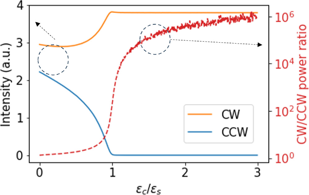
Fig. 4. Dependence of lasing intensity contrast between CW and CCW modes on the ratio between cross- and self-saturation coefficient.  Current in this simulation is chosen at I = 3 mA, well above the threshold.
Download figure:
Standard image High-resolution imageIn addition to the confirmation of previous research, to further understand the importance of self- and cross-saturations in the unidirectional lasing, we compare three scenarios, namely, the behavior of systems without gain saturation, with only self-gain saturation, and with both self- and cross-gain saturations, to identify phenomena that exclusively exist due to the existence of gain saturation. In all three cases, numerical solutions for a steady state are found well above threshold. The results exhibit fluctuation due to the introduction of random spontaneous emission. Figure 5(a) shows the robustness against backscattering introduced by saturation coefficient with  and I = 3 mA. With self-saturation but no cross-saturation, both modes will be suppressed by a great amount, and the ratio will be very low. In cases where both self- and cross-saturation are present, the system maintains high unidirectionality up to the order of 10−5. With no saturation at all, robustness still exists, but with a much lower power ratio and lower tolerance of κ. Even as κ grows beyond 10−5, the power ratio between CW and CCW modes is still the greatest in cases where both saturation terms are present. The presence of nonlinear gain is crucial for sustaining stable unidirectional lasing, which is key to the lasing of non-trivial ring-shaped devices with gratings or scatterers.
24,25,27) Figure 5(b) shows the effect of coupling coefficient with the S-shaped coupler s to the power ratio in the three cases with
and I = 3 mA. With self-saturation but no cross-saturation, both modes will be suppressed by a great amount, and the ratio will be very low. In cases where both self- and cross-saturation are present, the system maintains high unidirectionality up to the order of 10−5. With no saturation at all, robustness still exists, but with a much lower power ratio and lower tolerance of κ. Even as κ grows beyond 10−5, the power ratio between CW and CCW modes is still the greatest in cases where both saturation terms are present. The presence of nonlinear gain is crucial for sustaining stable unidirectional lasing, which is key to the lasing of non-trivial ring-shaped devices with gratings or scatterers.
24,25,27) Figure 5(b) shows the effect of coupling coefficient with the S-shaped coupler s to the power ratio in the three cases with  and I = 3 mA. The model with no saturation will have high unidirectionality only with high enough coupling, in agreement with the result in Fig. 2(b). The model with self-saturation but no cross-saturation will have consistently low unidirectionality as both modes are equally suppressed. With the presence of both saturation terms, the system can exhibit higher unidirectionality than predicted by the linear model. Notably, such high unidirectionality is maintained even when
  reduces to 0. This is in agreement with the experimental observations that a high power contrast can be achieved even in completely symmetrical designs.
33,48–50)
reduces to 0. This is in agreement with the experimental observations that a high power contrast can be achieved even in completely symmetrical designs.
33,48–50)

Fig. 5. Comparison of power ratio between models with and without gain saturations as a function of (a) backscattering κ, with  and I = 3 mA and (b) coupling with S-shaped coupler s, with
  and I = 3 mA.
Download figure:
Standard image High-resolution image3.2.2. Effect of coupling coefficient 

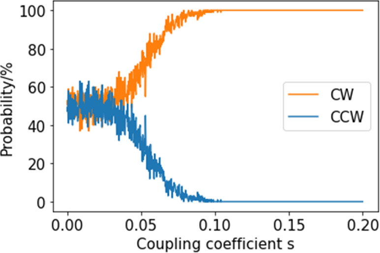
As discussed in Sect. 3.2.1, the power contrast between CW and CCW modes shows very limited dependence on the amount of coupling to the S-shaped resonator. However, without any asymmetrical design, the direction of lasing is non-deterministic. The direction in which lasing is observed depends on the small Q factor differences between the two modes and the way cavities get excited. In our model, such randomness is captured by the random nature of the spontaneous emission term. Figure 6 shows how the coupling to the S-shaped resonator acts to overcome the randomness in achieving deterministic lasing in the desired direction, with  and I = 3 mA. Steady state solution is found repeatedly for 100 times for each coefficient of coupling to the S-shaped coupler, s. The numbers of times that CW or CCW mode starts lasing are recorded, and the probability for lasing in each direction is plotted as a function of s. When s = 0, the S-shaped resonator has no effect to the system, and it is equally possible to obtain lasing in CW or CCW direction. As s increases, lasing in the designated direction becomes more and more likely, and above a certain threshold around s = 0.1, lasing in the CW direction is guaranteed. The S-shaped coupler needs to provide strong enough discrimination between the two modes to overcome spontaneous emission, fabrication imperfection and noise, to guarantee lasing in the desired direction.
Fig. 6. The probability to obtain lasing in CW and CCW direction as coupling coefficient with the S-shaped resonator s changes, with  and I = 3 mA.
Download figure:
Standard image High-resolution image
4. Conclusions
We constructed a set of rate equations with semiconductor dynamics included in detail, to describe the unidirectional lasing behaviors inside a ring resonator with an S-shaped coupler. Key parameters towards unidirectionality have been identified and quantitatively discussed. The results reveal the role of gain saturation in achieving highly unidirectional lasing even without asymmetric coupling from the S-shaped coupler, as well as robustness against backscattering. We also found that the deterministic lasing in the designated direction relies on significant coupling with the asymmetric S-shaped coupler. Our new findings around the deterministic unidirectional lasing in ring resonators against backscattering can be applied to the design of non-reciprocal devices with different shapes and materials, including but not limited to on-chip devices generating structured light such as an optical skyrmion beam. 25)
Acknowledgments
The authors would like to acknowledge Yasutomo Ota of Keio University for fruitful discussions. This work was supported by JST CREST(JPMJCR19T1).