
Abstract
In this paper, a metal–insulator–metal straight waveguide structure with quadrant ring resonators (QRRs) is theoretically presented. The transmission spectra at output ports are studied by the finite element method (FEM). The simulation results show great filtering effects at specific wavelengths. In order to unidirectionally control plasmonic flows at waveguide junctions, the original design has been expanded to T- and X-shaped waveguides with the QRRs. The results reveal that obvious Fano effects can be achieved in T-shaped systems.
Export citation and abstract BibTeX RIS
Surface plasmon polaritons (SPPs), i.e., coupled modes of plasmons and photons, propagate along a metal–dielectric interface.1) Most plasmonic efforts have been devoted to the issues on SPPs originating from the electromagnetic wave coupling to the free electron oscillation in a metallic surface. When the SPPs propagate along flat interfaces, the electromagnetic field is tightly confined at the interface and decays exponentially into the two adjoining media. Because of their ability to break the diffraction limit and manipulate light at subwavelength scales, SPPs are considered to be promising candidates for constructing next-generation ultracompact integrated photonic circuits.2) Therefore, metal–insulator–metal (MIM) plasmonic waveguides are one of the hottest research topics.3,4) Compared with conventional waveguide devices, the MIM waveguides are more compact and easier to integrate into photonic circuits. Various plasmonic waveguide devices, such as plasmonic splitters,5) bends,6) filters,7) and sensors8) have been proposed. A large number of MIM structures9–12) have been utilized in photonic integrated circuits. The gap plasmon waveguides12) are considered to have unique advantages because they can be easily integrated into optical circuits. MIM waveguide splitters are essential components of plasmonic integrated circuits. Veronis and Fan first proposed a T-shaped MIM waveguide splitter and introduced the concept of characteristic impedance for such systems to account for their behaviors.5) Following this work, the coupled mode method was applied to quantitatively predict the coupling efficiency from infinite- and finite-length nanoslits to planar MIM waveguide structures.13) For equal splitting, an antireflection (AR) resonator was inserted in the input waveguide to diminish the reflection.14) For unequal splitting, stubs,15) a Bragg grating,16) or a joint cavity17) was inserted into the T-shaped splitter to guide the light along the desired output arm. Besides the above T-shaped MIM splitters, a rectangular ring resonator18) or slot cavity19) has been introduced to MIM waveguide systems to achieve 1 × N splitting. The ring resonators20) configured by ring waveguides are widely used in traditional optical circuits functioning as fitters, couplers, and wavelength division multiplexers (WDM). The SPP circular or rectangular ring resonators and couplers have been numerically and experimentally proposed.12,21)
Many plasmonic nanostructures have been investigated to achieve compact optical devices. These devices can be studied on the basis of electromagnetically induced transparency (EIT), which decreases the light absorption resulting from quantum interference.22,23) Recently, a resonant effect named Fano resonance has drawn much attention; it results from the interference between a discrete and a continuum state.24) The Fano effects have occurred in traditional optical systems that present a special asymmetric line.25)
In this paper, on the basis of the straight waveguide with quadrant ring resonators (QRRs), T- and X-shaped waveguides with QRRs have been proposed to unidirectionally control plasmonic flow at junctions, which work as plasmonic filters. By applying the ring resonance theory, the excited SPP modes can be controlled to propagate towards specific output ports in the T- and X-shaped systems. Our designs have been verified by the finite element method (FEM). The simulation results reveal that Fano effects and the plasmonic-induced transparency (PIT) phenomenon can be achieved in our designed systems. SPP waveguide–resonator systems pave the way to the realization of integrated plasmonic circuits.
The proposed structure with a QRR is schematically depicted in Fig. 1(a). Here, ports A and B are input and output ports, respectively. We assume that the insulator medium is air (εi = 1) and the metal is silver. The relative dielectric constant of silver is given by the Drude model:
Here, ε∞ = 3.7 is the relative permittivity at infinite frequency, ωp = 1.38 × 10¹⁶ Hz is the bulk plasma frequency, γ = 2.73 × 10¹³ Hz is the damping frequency of the oscillations, and ω is the circular frequency of the incident electromagnetic radiation. The width w is chosen as 50 nm. r = r2 − w/2 (in fact, r = (r1 + r2)/2; r1 is the radius of the internal circle, r2 is the radius of the external circle) is the effective radius of the quadrant ring. Therefore, the propagation constant β of the incident wave and the effective refractive index in the straight waveguide are given by the following equation:

Here, k0 is the wave vector of the electromagnetic wave in free space.
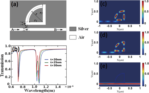
Fig. 1. (a) Schematic structure of QRR. (b) Transmission spectra at port B. Magnetic intensity distributions |Hz|2 for controlling SPP flows with t = 20 nm: (c) λr = 1042 nm, (d) λr = 1080 nm, and (e) λr = 1550 nm.
Download figure:
Standard image High-resolution imageWhen the incident wavelength meets the ring resonant condition, QRRs can affect the SPP transmission by coupling energy from the straight waveguide. The resonant condition of QRRs could be written as

where neff1 = β/k0 = βλ/2π is the effective refractive index in the straight waveguide. neff2 is the effective refractive index in the quadrant ring waveguide, which is in agreement with the theory of resonant ring expressed by the complex function transcendental equation:8)

Here, the wave vector of the quadrant ring satisfies  , where ε0 and μ0 are the dielectric constant and permeability in vacuum, respectively. εr = (neff2)2/μ0 is the relative effective dielectric constant of frequency. Jn is the Bessel function of the first kind with order n, and Nn is the Bessel function of the second kind with order n.
  and
and  are the derivatives of the Bessel function with kr as the variable. The total length of the midline of QRR can be denoted as d1 + d2, where d1 = 2r2 and d2 = πr/2. m is an arbitrary positive integer and λr is resonant wavelength.
The transmission spectra of port B are shown in Fig. 1(b), and three resonance wavelengths could be found when the waveguide parameter r2 was 430 nm, and the intervals between the waveguide and the QRR, t, were 20, 25, and 30 nm. It allows lossless bending around the corner when w is 50 nm.5) For the second-order resonance mode m = 2, the resonant wavelength is expected to be at λr = 726 nm. For the first-order resonance mode m = 1, the resonant wavelengths are λr = 1042 and 1080 nm, which means that one resonant mode splits into two resonances. This phenomenon was reported in Ref. 21. The resonant mode is split into two standing-wave modes owing to the nonuniform distribution of neff between corners and the straight waveguide. The quadrant ring waveguide has no corner so that it does not contribute to splits. With increasing intervals (t), the transmission peaks between two resonances also increase, which is the PIT-like phenomenon. The corresponding field distributions |Hz|2 at 1042 and 1080 nm are shown in Figs. 1(c) and 1(d), respectively. It is clear that the two standing-wave modes respectively occupy the corners [Fig. 1(c)] and the straight waveguide [Fig. 1(d)], so the same resonant modes have different effective waveguide lengths corresponding to the two resonant wavelengths. The standing wave in the main straight waveguide owing to the SPPs propagating forward and reflecting from QRR is presented. As the incident light satisfies the resonance condition, the energies can be confined in QRR as the standing wave mode so that the transparency valleys can be achieved. When the wavelength is 1550 nm, the magnetic intensity distributions |Hz|2 with the high transmission are shown in Fig. 1(e). According to the above analysis, this structure can be utilized as an effective filter.
The schematical T-shaped waveguide structure with a QRR is shown in Fig. 2(a). When the incident wavelength is satisfied under the resonant conditions, the incident energies will be coupled into the QRR and the SPP flows can be controlled at waveguide junctions. As shown in Fig. 2(b), the transmission spectra at t = 30, 25, and 20 nm are expressed in red, green, and blue lines, respectively. The solid and dashed lines represent the transmission spectra of ports B and C, respectively. The resonances occur at wavelengths of 729, 736, and 750 nm. The obvious redshifts of the transparency peaks can be found when the internal t continues to decrease. Transmission spectra at port B in Fig. 2(b) show obvious Fano resonance effects. When the incident port is on the left port A, the structure acting as a unidirectional launcher is as shown in Fig. 2(c). When the incident port is changed to the right port C, the structure acting as a reflector is as shown in Fig. 2(d). Next, the effect of the interval t was investigated because SPP flow control requires a high coupling efficiency between the main waveguide and the QRR. Figure 3(c) shows the corresponding transmission spectra represented by solid and dashed lines. The solid line exhibits a wide bandwidth, which can be explained as a quasi-continuum state, as shown in Fig. 3(a), while another spectrum with a narrower bandwidth can be presented as a discrete state, as shown in Fig. 3(b). Those two states can be obtained by disassembling the T-shaped waveguide into L-shaped and straight waveguides. The total transmission of port B shows great Fano effects around the peak of the discrete state, which can be explained by the coherent interference between quasi-continuum and discrete states.26) Figure 4(a) shows the transmission spectrum of port B, indicating as a wonderful PIT-like phenomenon resulting from the coherent interference between two states when port C is closed.

Fig. 2. (a) Schematic structure of the T-shaped waveguide with a QRR. (b) Transmission spectra at port B (solid line) and port C (dash line) with t = 30, 25, and 20 nm represented by red, green, and blue lines, respectively. Magnetic intensity distributions |Hz|2 for controlling SPP flows: (c) input in port A and (d) input in port C.
Download figure:
Standard image High-resolution image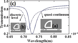
Fig. 3. (a) Schematic structure of the quasi-continuum. (b) Schematic structure of the discrete state. (c) Two transmission spectra are represented by solid and dashed lines.
Download figure:
Standard image High-resolution image
Download figure:
Standard image High-resolution image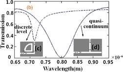
Fig. 4. (a) Transmission spectrum of the internal structure. (b) Quasi-continuum and discrete states transmission spectra. (c, d) Schematic structure corresponding to two states.
Download figure:
Standard image High-resolution imageIn this section, different X-shaped waveguides with QRR structures can be achieved to control SPP flows. The magnetic intensity distributions in the junction structures with QRRs for L = 430 nm are indicated in Fig. 5. The interval t is set as 20 nm. The incident wavelength is fixed at the resonant wavelength of 750 nm, which is shown in Fig. 2(b). For the X-shaped waveguide with a QRR in Figs. 5(a) and 5(b), the energies mainly flow to the waveguide branch B with incident light input from port A. Most of the transmitted energy is reflected to incident port C where the strong standing waves are presented. Here are still parts of the incident energies transmitting to output port D. When the X-shaped waveguide is equipped with two QRRs at x-axial symmetric positions, which are depicted in Figs. 5(c) and 5(d), the X-shaped waveguide can act as the splitter or the reflector for the incident wave from port A or B. When the two QRRs are placed at the central symmetry, as shown in Figs. 5(e) and 5(f), the structure can achieve the same function as the previous T-shaped systems, as shown in Figs. 2(c) and 2(d). These results clearly demonstrate that the QRR structures have a high potential to be applied in perpendicular waveguide junctions to realize SPP flow control.
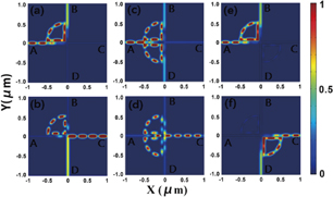
Fig. 5. Magnetic intensity distributions |Hz|2 for controlling SPP flows with t = 20 nm: (a, b) X-shaped waveguide with a QRR, in which ports A and C are input ports. (c, d) X-shaped waveguide with double QRRs at x-axial symmetric positions, in which ports A and C are input ports. (e, f) X-shaped waveguide with double QRRs at central symmetry positions, in which ports A and C are input ports.
Download figure:
Standard image High-resolution image
In this paper, we theoretically presented the MIM straight waveguide structure with the QQRs. The simulation results obtained by FEM show great filtering effects at specific wavelengths. We numerically studied the transmission features of the T- and X-shaped waveguides with QRRs. The simulation results demonstrated that the energy can be coupled in QRR with high efficiency to control SPP flows smoothly; simultaneously, the B output port has shown Fano effects and the PIT-like phenomenon. We can utilize these structures to achieve SPP unidirectional flows at the waveguide junctions. We consider that the QRR will have important application prospects in optical integration, communication, and information processing.
Acknowledgments
This study was supported by the National Natural Science Foundation of China (Grant Nos. 11347196, 11404143, and 61474113), the Jiangsu Natural Science Foundation (Grant No. BK20140167), the Beijing Natural Science Foundation (Grant No. 4132076), the Key Laboratory Open Fund of Institute of Semiconductors of CAS (Grant No. KLSMS-1405), and the National Training Programs of Innovation and Entrepreneurship for Undergraduates of China (Grant No. 201410295027).