Abstract
Innovation in the design of electrolyte materials is crucial for realizing next-generation electrochemical energy storage devices such as Li–S batteries. The theoretical capacity of the S cathode is 10 times higher than that of conventional cathode materials used in current Li–ion batteries. However, Li–S batteries suffer from the dissolution of lithium polysulfides, which are formed by the redox reaction at the S cathode. Herein, we present simple solvate ionic liquids, glyme–Li salt molten complexes, as excellent electrolyte candidates because they greatly suppress the dissolution of lithium polysulfides. The molten complexes do not readily dissolve other ionic solutes, which leads to the stable operation of the Li–S battery over more than 400 cycles with discharge capacities higher than 700 mAh g-sulfur−1 and with coulombic efficiencies higher than 98% throughout the cycles. Such high performance has not been realized to the best of our knowledge. Furthermore, the addition of a nonflammable fluorinated solvent, which does not break the solvate structure of the glyme–Li salt molten complexes, greatly enhances the power density of the Li–S battery. The strategic design of electrolyte properties provides opportunities for the development of new electrochemical devices with many different electrode materials.
Export citation and abstract BibTeX RIS
Among the currently available secondary batteries, lithium-ion batteries (LIBs) have the highest energy density and have become essential for energy storage in modern society. The energy density of commercialized LIBs is in the range 100–200 Wh kg−1.1,2 However, the driving range of current electric vehicles (EVs) with LIBs is limited to less than 200 km, whereas that of cars equipped with internal combustion engines is typically more than 500 km.3 Thus, next-generation batteries with much higher energy densities than conventional LIBs are required to realize the full potential of electrified transport. The effective utilization of renewable energy also requires high-energy-density secondary batteries. The present LIBs use intercalation compounds as electrode active materials.1,2 The active anode material is typically graphite, which has a theoretical capacity of 372 mAh g−1. The cathode materials currently in use consist of transition metal compounds such as LiCoO2 and LiFePO4, which have theoretical capacities of 137 and 170 mAh g−1, respectively. At present, the energy density of LIBs has been limited by the cathode capacity; therefore, research on alternative cathode active materials is crucial for developing high-energy-density next-generation batteries. One of the most promising cathode materials is elemental sulfur (S8) owing to its high theoretical capacity (1672 mAh g−1), which is approximately 10 times larger than that of other conventional cathode materials.3,4 In addition, sulfur is cheap and naturally abundant, whereas conventional LIB cathode materials typically include rare metals.
There have been many important studies on Li–S batteries;5–10 however, cells using a S cathode in conjunction with liquid electrolytes generally suffer from low active material utilization and rapid capacity fade with charge–discharge cycling. The low utilization is caused by the insulating nature of S compounds9,10 and the slow redox kinetics.10 Important advances have been made recently using nanocomposite electrodes consisting of sulfur and carbonaceous materials.11–13 Nanocomposite electrodes are useful for achieving effective current collection from sulfur and lithium polysulfide (Li2Sm: 2 ≤ m ≤ 8) during charge/discharge of the Li–S cell. However, a bottleneck remains with respect to the dissolution of Li2Sm,5–8 which causes low columbic efficiency of discharge/charge and rapid capacity fade for the Li–S cell. Li2Sm forms at the S cathode as a reaction intermediate of the redox conversion process and it is easily dissolved in conventional organic electrolytes consisting of polar solvents and Li salts.
Ether-based solvents such as tetrahydrofuran, 1,3–dioxolane, and dimethoxyethane have been used to dissolve Li salts and are used as liquid electrolytes for Li–S batteries. Li2Sm dissolves in the electrolyte as a result of the high donating capacity of the solvent.14–17 The solubility of Li2Sm in ether-based liquid electrolytes is extremely high. Solvents with high donor numbers (DN) dissolve Li2Sm, because the electrostatic force between Li+ and Sm2− is not very strong when the Sm2− chain length is long. Highly donating solvents coordinate to the Li+ cation and effectively cause the dissociation of the lithium cation from the anion. The dissolved Li2Sm can then directly react with the Li metal anode, leading to a subsequent low coulombic efficiency of discharge/charge.8 The addition of LiNO3 to the electrolyte has been reported to be useful in preventing this direct reaction by generating a protective film composed of LixNOy and LixSOy on the surface of the Li metal anode.18,19 However, repeated charge–discharge cycling may destroy the surface film. Therefore, the development of alternative electrolytes that do not dissolve the Li2Sm active material is necessary for building highly durable Li–S cells with a stable charge–discharge operation.
When designing these cells, the donor ability of the solvent needs to be low to suppress the solubility of Li2Sm. However, the Li+ conductivity needs to be high for the cell to operate. Because Li + is a strong Lewis acid, an aprotic solvent with a high donor number is required to ensure the dissociation of the lithium salt and the subsequent stabilization of the lithium cation in solution. To overcome this discrepancy in the electrolyte requirements, one option would be to use solid electrolytes, such as inorganic and polymer electrolytes. Solid electrolytes are effective in physically blocking the diffusion of Li2Sm, and there have been several reports on the effectiveness of solid-state Li–S cells.20–25 Although solid electrolytes have certain beneficial properties, there are still many difficulties in forming effective solid–electrolyte/solid–electrode interfaces for electrochemical reactions. Another option is to use conventional ionic liquids,26–28 in which a lithium salt is dissolved. Ionic liquids generally consist of weakly Lewis acidic cations and weakly Lewis basic anions.26–28 As a result, the dissolution of Li2Sm is found to be greatly reduced.29 However, the discharge and charge current (rate capability) was found to be low owing to the slow Li+ diffusion and low Li+–transference numbers.30 Finding a liquid electrolyte that does not dissolve Li2Sm, but has high Li+ conductivity would be an important breakthrough toward achieving highly stable operation of Li–S cells. Herein, we present simple solvate ionic liquids,31 glyme–Li salt molten complexes,32–37 as excellent electrolyte candidates; these electrolytes greatly suppress the dissolution of lithium polysulfides. Stable operation of the Li–S battery for more than 400 cycles with a discharge capacity higher than 700 mAh g-sulfur−1 and a coulombic efficiency higher than 98% throughout the cycles has been demonstrated. Furthermore, the addition of a nonflammable fluorinated solvent, which does not break the solvate structure of the glyme–Li salt molten complexes, has been shown to enhance the power density of the Li–S battery greatly.
Experimental
Electrolytes
Lithium bis(trifluoromethanesulfonyl)amide (Li[TFSA]) was dried under vacuum at 80°C for 12 h prior to use. The [Li(glyme)x][TFSA] electrolytes were prepared by mixing the purified glyme, triglyme (G3) or tetraglyme (G4), with Li[TFSA] in an Ar-filled glove box. A hydrofluoroether solvent, 1,1,2,2–tetrafluoroethyl 2,2,3,3–tetrafluoropropyl ether (HFE), was mixed with [Li(G4)1][TFSA] in a glove box to obtain [Li(G4)1][TFSA]/HFE electrolytes. The water content in the electrolytes was under 30 ppm as determined by Karl Fisher titration (CA-07, Mitsubishi Chemical). The ionic conductivities of the [Li(glyme)x][TFSA] electrolytes were determined by the complex impedance method over the frequency range of 500 kHz–1 Hz using an ac impedance analyzer (VMP2, Princeton Applied Research) with a sinusoidal alternating voltage amplitude of 10 mV root mean square. A cell equipped with two platinized Pt electrodes was used for conductivity measurements. The cell constant was determined using a standard 0.01 mol dm−3 aqueous solution of KCl at 25°C. The viscosities and densities of the electrolytes were measured using a viscometer (SVM3000, Anton Parr). The self-diffusion coefficients of components in the electrolytes were evaluated using pulsed-gradient spin–echo NMR (PGSE–NMR; ECX400, JEOL) measurements with a 9.4 T narrow bore superconducting magnet equipped with a pulsed field gradient probe (JEOL) and a current amplifier to determine the self-diffusion coefficients of each component in the [Li(G4)1][TFSA]/HFE mixtures: glymes (1H, 399.7 MHz), TFSA (19F, 376.1 MHz), HFE (19F, 376.1 MHz), and Li cation (7Li, 155.3 MHz). The experimental procedure for the PGSE–NMR measurements has been described in detail elsewhere.38
Solubility measurements of S8 and Li2Sm in the electrolytes were conducted as follows. UV–Vis spectroscopic measurements for electrolytes containing S8 were performed using a spectrometer (UV–2500PC, Shimadzu). Samples were prepared by dissolving a known amount of S8 in [Li(G4)x][TFSA] with vigorous stirring at 60°C for 24 h and then keeping at 30°C for 48 h without stirring. The absorbance at 266 nm had a linear correlation with the S8 concentration, which allowed quantitative determination of the concentration of S8 using a calibration line. Li2Sm solutions were prepared by the direct reaction of S8 with Li2S (8Li2S + (m – 1)S8 → 8Li2Sm), as reported by Rauh et al.39 The saturated solution of Li2Sm in the electrolytes was prepared as follows. S8 and Li2S powders (Aldrich) were mixed in various ratios using an agitating mortar in an Ar-filled glove box. The mixed powder was stirred in a vial containing [Li(glyme)x][TFSA] at 60°C for 100 h and then kept at 30°C for 48 h without stirring. The [Li(glyme)x][TFSA] was considered to be saturated with Li2Sm, because precipitation was observed at the bottom of the vial. The supernatant liquid was subsequently subjected to UV–Vis spectroscopic analysis. The solubility limit of Li2Sm was measured by the reported procedure29 using a two-compartment cell: electrochemical oxidation of the solubilized Li2Sm to S8 followed by the quantification of the converted S8 using UV-vis spectroscopy.
Carbon/Sulfur composite electrode
Porous carbon (Ketjen black, specific surface area: 1270 m2 g−1) and elemental sulfur (S8) were mixed using an agitating mortar. The mixture was transferred to a vial and kept at 155°C for 6 h, according to the method reported by Ji et al.11 S8 melted and diffused into the pores of the carbon during the heat-treatment. The C/S composite cathode was then prepared by mixing the C/S composite with poly(vinyl alcohol) (PVA, degree of polymerization: 3100–3900, degree of saponification: 86–90 mol%). Prior to mixing, PVA was dissolved in N–methylpyrrolidone (NMP) at 100°C and subsequently cooled to room temperature. The C/S composite and PVA/NMP solution was then mixed to form a slurry, which was spread on an Al foil current collector. The slurry was dried in an oven at 80°C for 12 h. A coin cell (2032–type) was fabricated in a glove box using the porous composite cathode sheet and a porous separator consisting of a Li metal foil anode and the electrolyte. Galvanostatic charge–discharge measurements of the Li–S cells were conducted at 30°C using a charge–discharge measurement instrument.
Results and Discussion
Solubility of Li2Sm in glyme–Li salt molten complexes
The strong Lewis acidity of the Li+ cations is neutralized by the strong Lewis basicity. The strong acidity results in the formation of stable solvates with donating solvents owing to donor–acceptor interactions. Glymes, which are oligoethers with the chemical structure of CH3–O–(CH2–CH2–O)n–CH3 form complexes with Li salts.40–47 The formation of the complexes should weaken the donor ability of the ethers because the lone pairs of the ether oxygen are donated to the Li+.32 The melting point of a glyme–Li salt complex changes according to the structures of the anion and glyme. If an appropriate anion and glyme are selected, then the melting point of the glyme–Li salt complex becomes lower than room temperature. Because the coordination number of Li+ is typically 4–5, the glyme forms a 1:1 complex with Li[TFSA],32,35 when n = 3 or 4 in CH3–O–(CH2–CH2–O)n–CH3. Hereafter, triglyme (n = 3) and tetraglyme (n = 4) are abbreviated as G3 and G4, respectively. The equimolar complex, [Li(G3 or G4)1][TFSA], remains in the liquid state at room temperature and exhibits an ionic conductivity of ca. 10−3 S cm−1.33 [Li(G3 or G4)1][TFSA] can be regarded as a solvate ionic liquid31 that consists of a complex cation [Li(G3 or G4)1]+ and a [TFSA]− anion. The donor ability of [Li(G3)1][TFSA] and [Li(G4)1][TFSA] equimolar complexes was evaluated using a solvatochromc method. The maximum absorption wavelength (λCu) of the (acetylacetonate)(N,N,N',N'–tetramethylethylenediamine)copper(II) tetraphenylborate ([Cu(acac)(tmen)][BPh4]) solvatochromic probe shows good correlation with the DN of the molecular solvents, where a higher λCu indicates a stronger donor.48 λCu for both [Li(G3)1][TFSA] and [Li(G4)1][TFSA] was estimated to be 544 nm, which corresponds to a DN of ca. 10. The DNs of G3 and G4 have previously been reported to be 14.0 and 16.6, respectively.49 As expected, the donor ability of the glyme molecule is significantly weakened by complexation. This is because all of the lone pairs of the oxygen atoms are donated to the strongly Lewis-acidic Li+ cation.
Figure 1 shows UV–Vis spectra of the solutions saturated with S8 and Li2Sm. The spectrum of each solution was dependent on the mixing ratio of S8/Li2S. The peak assignments were not clear, because the polysulfide formed in the electrolyte is a mixture of several species with different chain lengths due to the disproportionation of Sm2−.50,51 However, it is clear that the polysulfide species changes according to the electrolyte composition. For example, the peak at 620 nm, which was previously assigned to the S3− anion radical,51 was observed for the [Li(G4)4][TFSA] solution, but was not observed in the spectrum for the [Li(G4)1][TFSA] solution. Although the exact compositions of the polysulfide species in the electrolytes are difficult to determine precisely, the overall absorbance due to polysulfides in [Li(G4)4][TFSA] was much larger than that in [Li(G4)1][TFSA], which suggests that the solubility of Li2Sm is higher for solutions with excess glyme.
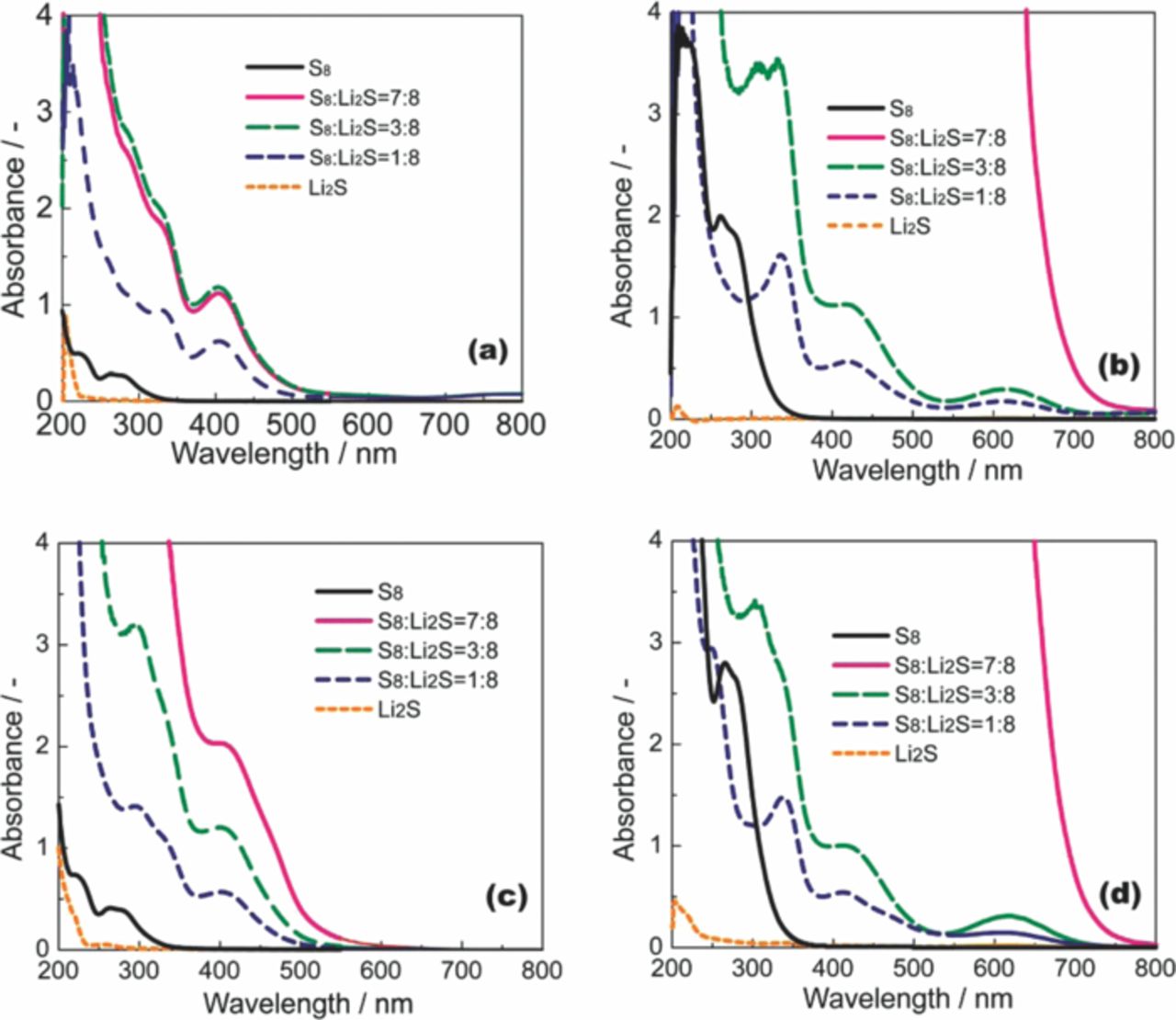
Figure 1. UV–Vis spectra for [Li(G3)x][TFSA] ((a) x = 1, (b) x = 4) and [Li(G4)x][TFSA] ((c) x = 1, (d) x = 4) saturated with S8 and Li2Sm.
The solubility limit of Li2Sm in a solution consisting of G3 or G4 and Li[TFSA] was quantitatively determined in the same manner as reported in our previous work.29 The result is shown in Figure 2. The solubility of Li2Sm (presented as total S concentration in the unit of atomic–S concentration) changes significantly depending on the molar ratio of glyme in the solution. In particular, the total S concentration in a solution saturated with Li2S8 increases significantly with the molar ratio of glyme. In contrast, the solubility of other forms of Li2Sm with shorter chain lengths (m ≤ 4) is comparatively independent of the molar ratio of glyme in the solution. This suggests that the chain length of the polysulfide anion has a significant effect on the solubility of the salt. The solubility limit of Li2S8 in [Li(G3)1][TFSA] was 29.0 ± 1.0 mM (corresponding to [Li2S8] = 3.6 ± 0.13 mM). In contrast, the solubility limit of Li2S8 in a solution of [Li(G3)4][TFSA] that contains excess glyme is 5889 ± 113 mM. Thus, the solubility of Li2S8 diminishes with a decrease in the molar ratio of glyme. The donor ability of the glyme molecule diminishes upon complexation with Li+. Consequently, the ability of [Li(G3 or G4)x][TFSA] to dissolve Li2Sm decreases with a decrease in the molar ratio of glyme (x). In addition, the [TFSA]− anion is a weak Lewis-base.38 As a result, Li2Sm is poorly solvated in the solvate ionic liquid ([Li(G3 or G4)1][TFSA]).
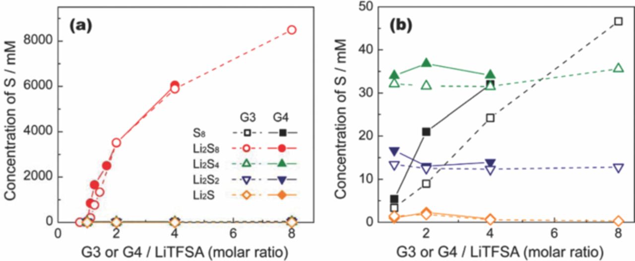
Figure 2. (a) Dependence of S8 and Li2Sm solubility limits on the molar ratio x of [Li(G3 or G4)x][TFSA] at 30°C, and (b) expanded view of lower S concentration region.
Performance of Li–S cells using glyme–Li salt molten complex electrolytes
Coin-type Li–S cells were fabricated to evaluate the feasibility of the solvate ionic liquids with a S cathode. A porous carbon with a high specific surface area of 1270 m2 g−1 was used as a substrate for S. The C/S composite was mixed with a polymeric binder (poly(vinyl alcohol); PVA) to form a cathode sheet. The cell was prepared in the fully charged state, and the charge–discharge cycle sequence was defined as follows: 1st discharge → 2nd charge → 2nd discharge → 3rd charge → 3rd discharge. The coulombic efficiency was defined as (Nth discharge capacity)/(Nth charge capacity). The specific capacity of the cell was then calculated based on the mass of S. The gravimetric current density of 1672 mA g−1, based on the mass of S, was defined as a rate of 1C, corresponding to a geometric current density of 1 mA cm−2. Galvanostatic charge–discharge curves of Li–S cells with [Li(G3)x][TFSA] electrolytes measured at low current densities are shown in Figure 3. Each cell shows discharge curves with two voltage regions. The initial discharge capacity of each Li–S cell was in the range 800–1000 mAh g−1, which corresponds to 50–60% of the theoretical capacity of elemental S. Sulfur usually has the cyclic S8 structure and is expected to exhibit a theoretical capacity of 1672 mAh g−1 if the reduction (S8 + 16Li+ + 16e− → Li2S) proceeds completely. Although the exact electrochemical reaction mechanism for S has not yet been identified, the voltage sloping region from 2.4 to 2.0 V in the discharge curves corresponds to the reduction of S8 to Li2Sm (typically m = 4) via the formation of Li2S8.20 The distinct differences between Li–S cells with different electrolytes were attributed to the charge–discharge cycle stability and coulombic efficiency. The coulombic efficiency of cells with [Li(G3)4][TFSA] rapidly decreased with each charge–discharge cycle (Figure 3a and 3c). The lower coulombic efficiency is attributed to the occurrence of the redox shuttle mechanism of Li2Sm within the cell during the charge and discharge processes. Dissolved Li2Sm, generated by the reaction at the C/S composite cathode, can diffuse to the Li metal anode. Li2Sm can then be further reduced to Li2Sl (l < m) on the Li metal surface after which it can diffuse back toward the composite cathode to be further reduced during discharge. It is subsequently oxidized when the cell is charging;8 thus, soluble Li2Sm behaves as a redox shuttle in the cell. This redox cycling between Li2Sm and Li2Sl during charge/discharge causes the low coulombic efficiency of the Li–S cell (decrease in the discharge capacity and increase in the charging capacity). In contrast, the cell with [Li(G3)1][TFSA] can be cycled more than 400 times while maintaining a coulombic efficiency above 98% (Figure 3b and 3d). This high efficiency over this large number of cycles can be attributed to the low solubility of Li2Sm in [Li(G3)1][TFSA], indicating that the solid state Li2Sm remains in the composite cathode and undergoes a reversible redox reaction. The solid-state redox reaction of the sulfur cathode in the [Li(G3)1][TFSA] solvate ionic liquid is distinctly different from that in conventional Li–S cells. In conventional electrolytes composed of a Li salt and an excess amount of aprotic solvent, the charge–discharge reaction of the sulfur cathode definitely involves the dissolution of the Li2Sm species in the electrolyte.
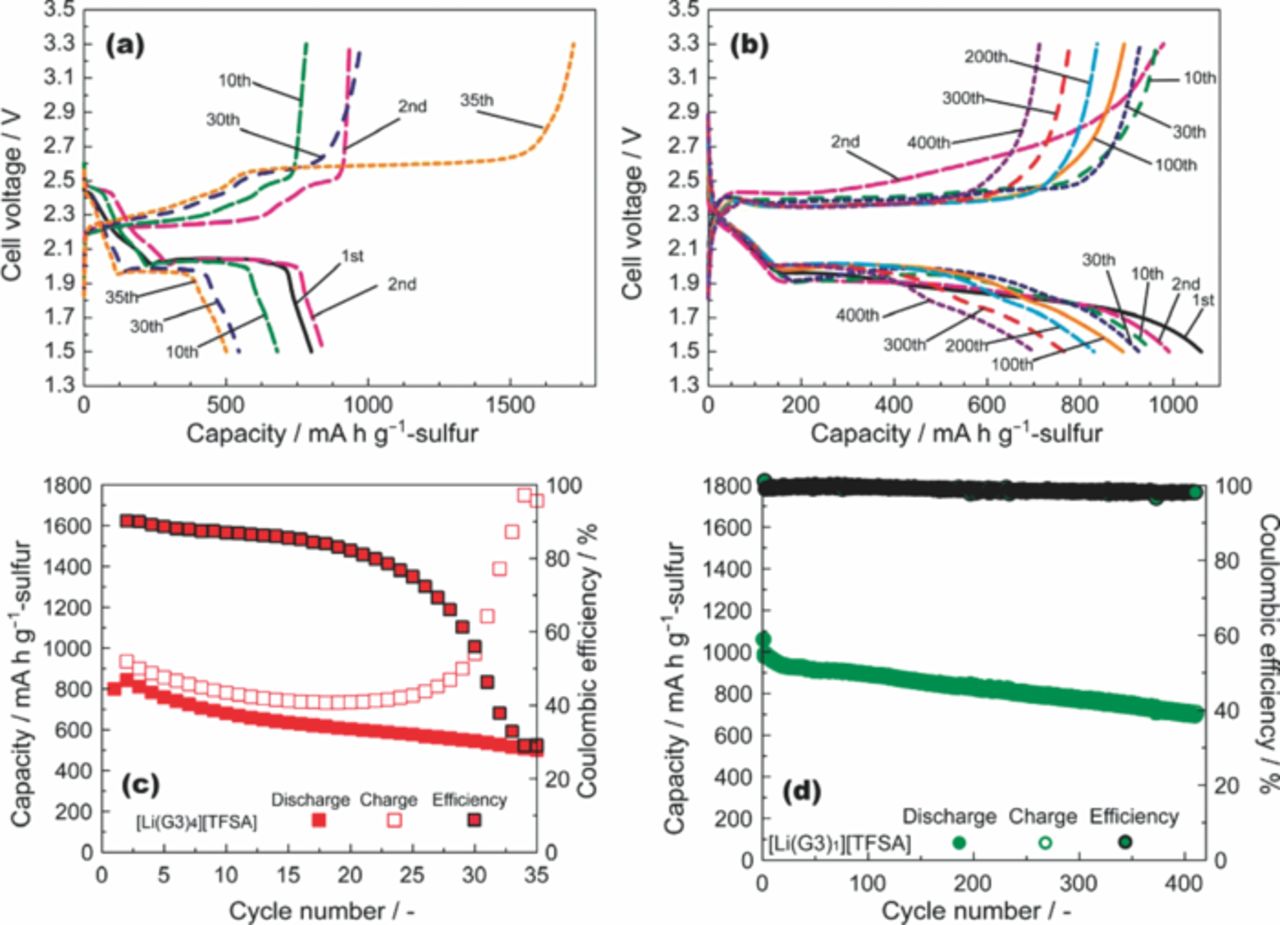
Figure 3. Discharge–charge curves of Li–S cells with (a) [Li(G3)4][TFSA] (mass ratio of S/C/PVA = 60:30:10) and (b) [Li(G3)1][TFSA] (mass ratio of S/C/PVA = 57:28:15). Discharge–charge capacities and coulombic efficiency of cells with (c) [Li(G3)4][TFSA] and (d) [Li(G3)1][TFSA] measured at 30°C with rates of 1/12 C and 1/18 C, respectively.
Effect of solvent addition on rate capability of Li–S cells
Further improvement in the Li–S cell performance is made possible by the addition of a second solvent. The conductivity of the solvate ionic liquid ([Li(G3 or G4)1][TFSA]) is ca. 10−3 S cm−1 (30°C), which is an order of magnitude lower than that of the conventional organic electrolytes currently used for LIBs.52 Furthermore, the viscosity of [Li(glyme)1][TFSA] is much higher than that of conventional organic electrolytes. We attempted to enhance the transport properties of the electrolytes by adding a second solvent to the [Li(glyme)1][TFSA]. The required properties of a second solvent for use in Li–S batteries are (i) reductive stability against the Li metal anode; (ii) chemical stability against Li2Sm in the cathode; (iii) miscibility with [Li(glyme)1][TFSA]; and (iv) low donor ability. These properties are important for maintaining the complex cation structure of [Li(glyme)1]+ and the low solubility of Li2Sm. A number of aprotic solvents have been investigated to determine the most suitable one. [Li(glyme)1][TFSA] is a liquid that dissociates into ions, even in the absence of a second solvent. As a result, the Li salt does not require further solvation.33–35 The solvate ionic liquid is miscible with various solvents but not with non-polar alkanes such as n–hexane and cyclohexane. A hydrofluoroether (HFE), 1,1,2,2–tetrafluoroethyl 2,2,3,3–tetrafluoropropyl ether, which has moderately low polarity, was determined to be a promising "non-flammable" second solvent.
The transport properties of the mixtures of [Li(G4)1][TFSA] and HFE are reported in Figure 4. The addition of HFE to [Li(G4)1][TFSA] resulted in a maximum ionic conductivity of 5.2 × 10⁻³ S cm−1 at 30°C at a concentration of 1 M [Li(G4)1][TFSA] in HFE (molar ratio of Li[TFSA]/G4/HFE = 1:1:4) as can be seen in Figure 4a. Figure 4b shows the self-diffusion coefficients of Li+, [TFSA]−, G4, and HFE. The diffusion coefficient increases with increasing molar ratio of HFE. The diffusion coefficients of G4 are identical to those of Li+, which suggests that Li+ and G4 diffuse together as a complex cation. The [TFSA]− anion had similar diffusion coefficients to those of Li+, which is not due to ion-pair formation but due to the similar hydrodynamic radii of [Li(G4)1]+ complex cation and [TFSA]− anion.34,35 In contrast, the HFE diffused faster than other components, which supports the assumption that the complex cation structure of [Li(G4)1]+ is retained in the [Li(G4)1][TFSA]/HFE mixtures. The HFE lowers the viscosity of the electrolyte and increases the mobility of [Li(G4)1]+ and [TFSA]−, but interacts less with [Li(G4)1][TFSA]. The relative dielectric constant of HFE at 25°C was measured as 6.21, which is lower than that of G4 (7.71)49. λCu for [Cu(acac)(tmen)][BPh4] in the pure HFE was 532 nm, which corresponds to a DN lower than 1038,48 and is lower than that of G4 (16.6).49 Thus, the HFE is less polar and has a lower donating ability as a solvent and as a result does not participate in the solvation of the Li salt. The HFE lowers the viscosity of the electrolyte and increases the mobility of the [Li(G4)1]+ and [TFSA]− ions; however, it interacts less with [Li(G4)1][TFSA]. The solubility of Li2Sm in the [Li(G4)1][TFSA]/HFE solution was also examined (Figure 5) and was found to be much lower than that in the absence of HFE.
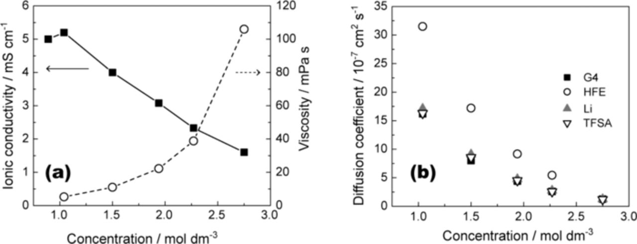
Figure 4. (a) Ionic conductivity and viscosity of [Li(G4)1][TFSA]/HFE as a function of Li[TFSA] concentration measured at 30°C. (b) Self-diffusion coefficients for Li+, TFSA, G4, and HFE in [Li(G4)1][TFSA]/HFE at 30°C.
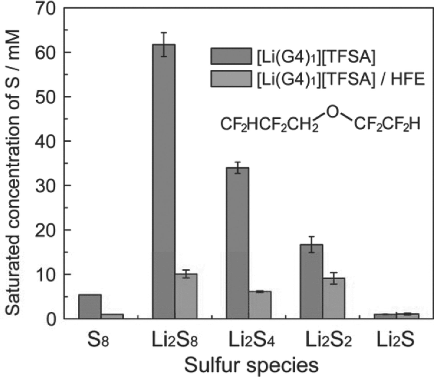
Figure 5. Comparison of S8 and Li2Sm solubility limits in [Li(G4)1][TFSA] and [Li(G4)1][TFSA]/HFE (molar ratio of Li[TFSA]/G4/HFE = 1:1:4) at 30°C. The structure of HFE is shown in the inset.
Figure 6b shows discharge–charge curves for a Li–S cell with [Li(G4)1][TFSA]/HFE. The discharge and charge profiles are very similar to those obtained for [Li(G4)1][TFSA] (Figure 6a). The charge–discharge cycle stability of the cell with [Li(G4)1][TFSA]/HFE is favorable and is comparable to that with [Li(G4)1][TFSA]. The initial discharge capacity of the cell with [Li(G4)1][TFSA]/HFE was higher than that obtained from cells without HFE (Figure 6c). This increase in capacity can be attributed to the lower mass transport resistance within the porous C/S composite electrode. The discharge capacity of the cell in the range 2.3–2.0 V did not increase with the addition of HFE, but the discharge capacity does show an increase in the low voltage plateau region for cells incorporating HFE. The mass transport resistance within the pores of the C/S composite cathode should increase with increasing depth-of-discharge (DOD). This is because the volume fraction of electrolyte in the composite cathode decreases owing to the volume change of the active material (the volume of active material becomes ca. 1.8 times larger during the electrochemical reaction of S8 → 8Li2S). The volume change may result in the pores of C/S composite being filled, so that the ionic conduction path within the composite electrode may be blocked. This blockage causes the end of discharge before complete utilization of the active material is achieved. Lowering the electrolyte viscosity would facilitate ionic conduction in the narrowed pores and increase the utilization of the active material. It should be noted that the energy efficiency of the cell with [Li(G4)1][TFSA]/HFE also increased (87% after the 20th cycle) compared with that of [Li(G4)1][TFSA] (80% after the 20th cycle) owing to enhancement of the plateau voltage.
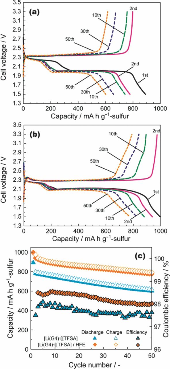
Figure 6. Discharge–charge curves of Li–S cells with (a) [Li(G4)1][TFSA] and (b) [Li(G4)1][TFSA]/HFE (molar ratio of Li[TFSA]/G4/HFE = 1:1:4) measured at 30°C with a rate of 1/12C. (c) Dependence of the discharge and charge capacities and coulombic efficiency on the cycle number. The mass ratio of S/C/PVA was 60:30:10.
The improvement in the rate capability of the Li–S cell with the addition of HFE was significant (Figure 7). The discharge capacity of the cell with [Li(G4)1][TFSA]/HFE is 510 mAh g−1, even at a relatively high current density of 1672 mA g−1 (1C rate). The capacity of the cell with [Li(G4)1][TFSA] was as low as 180 mAh g−1 at the same rate. The solubility of Li2Sm in [Li(G4)1][TFSA]/HFE is lower than in [Li(G4)1][TFSA]; therefore, the redox reaction mechanism of the C/S composite cathode in [Li(G4)1][TFSA]/HFE should be essentially identical to the process in [Li(G4)1][TFSA]. The improved rate capability is also attributed to the decrease in the mass transport resistance within the pores of the C/S composite electrode.
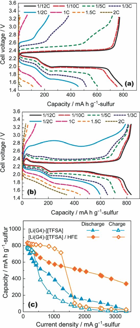
Figure 7. Discharge and charge curves of Li–S cells measured at various current densities with the (a) [Li(G4)1][TFSA] and (b) Li[TFSA]/G4/HFE = 1:1:4 electrolytes at 30°C. The cells were charged up to 3.3 V at a rate of 1/12C prior to each discharge test. The cells were discharged down to 1.5 V at a low current density with a rate of 1/12C prior to each charge test. (c) Comparison of discharge and charge rate capabilities for Li–S cells with [Li(G4)1][TFSA] and Li[TFSA]/G4/HFE = 1:1:4 electrolytes. The mass ratio of S/C/PVA was 60:30:10.
Conclusions
In summary, a novel "solvent-effect" on the reactions in a Li–S battery was demonstrated. The solubility of Li2Sm in the solvate ionic liquid ([Li(G3 or G4)1][TFSA]) was significantly suppressed compared with that in solutions containing an excess amount of glyme ([Li(glyme)x][TFSA] (x > 1)). The solubility of Li2Sm decreased with a decrease in the molar ratio of glyme (x) in [Li(glyme)x][TFSA]. All the glyme molecules coordinated with Li+ in the solvate ionic liquids such that there were no free glyme molecules. [Li(glyme)1][TFSA] had low donor ability because all the lone pairs of electrons on the oxygen atoms of the glyme were donated to the Li+ cation, resulting in a very poor Li2Sm solubility. The solvate ionic liquid suppressed the redox shuttle mechanism during charge–discharge of the Li–S cell. This is because the concentration of Li2Sm in the electrolyte was very low, which led to high coulombic efficiencies and a longer cycle life. Both S8 and Li2Sm were immobilized in the electrode with the solvate ionic liquid electrolyte ([Li(glyme)1][TFSA]). As a result, the electrochemical reactions of the S species occurred mainly in the solid phase. This is clearly in contrast to the [Li(glyme)x][TFSA] (x > 1) electrolytes, where dissolution of Li2Sm occurred during discharge and charge. The use of nonflammable HFE as a second solvent ([Li(glyme)1][TFSA]/HFE) further suppressed the dissolution of Li2Sm in the Li–S cell, resulting in high coulombic and energy efficiencies, good cycle stability, and improved rate capabilities. We believe that a strategy designed around the consideration of the physicochemical properties of electrolytes will provide new avenues for chemists and materials scientists to construct next-generation electrochemical devices with many different electrode materials such as active organic materials, which have not been used in practical batteries owing to dissolution problems.
Acknowledgments
This study was supported in part by the Advanced Low Carbon Technology Research and Development Program (ALCA) of the Japan Science and Technology Agency (JST) and by a Technology Research grant Program from the New Energy and Industrial Technology Development Organization (NEDO) of Japan.