

Abstract
Batteries that extend performance beyond the intrinsic limits of Li-ion batteries are among the most important developments required to continue the revolution promised by electrochemical devices. Of these next-generation batteries, lithium sulfur (Li–S) chemistry is among the most commercially mature, with cells offering a substantial increase in gravimetric energy density, reduced costs and improved safety prospects. However, there remain outstanding issues to advance the commercial prospects of the technology and benefit from the economies of scale felt by Li-ion cells, including improving both the rate performance and longevity of cells. To address these challenges, the Faraday Institution, the UK's independent institute for electrochemical energy storage science and technology, launched the Lithium Sulfur Technology Accelerator (LiSTAR) programme in October 2019. This Roadmap, authored by researchers and partners of the LiSTAR programme, is intended to highlight the outstanding issues that must be addressed and provide an insight into the pathways towards solving them adopted by the LiSTAR consortium. In compiling this Roadmap we hope to aid the development of the wider Li–S research community, providing a guide for academia, industry, government and funding agencies in this important and rapidly developing research space.
Export citation and abstract BibTeX RIS

Original content from this work may be used under the terms of the Creative Commons Attribution 4.0 license. Any further distribution of this work must maintain attribution to the author(s) and the title of the work, journal citation and DOI.
1. Foreword
James B Robinson1,2,3 and Paul R Shearing1,2,3
1 Electrochemical Innovation Lab, University College London, London WC1E 7JE, United Kingdom
2 The Faraday Institution, Quad One, Harwell Campus, Didcot OX11 0RA, United Kingdom
3 Authors to whom correspondence should be addressed.
Overview
There has been steady interest in the potential of lithium sulfur (Li–S) battery technology since its first description in the late 1960s [1]. While Li-ion batteries (LIBs) have seen worldwide deployment due to their high power density and stable cycling behaviour, gradual improvements have been made in Li–S technology that make it a competitor technology in certain applications. Research in this field has significantly accelerated in recent years, as developments in Li-ion technology have become increasingly incremental and the need for increased electrification of transport has become more pressing.
Li–S batteries (LiSBs) are among the most commercially mature of the 'beyond Li-ion' batteries, offering the prospect of cells that supersede the intrinsic limits of Li-ion technology along with the potential for substantially reduced costs and improved safety. However, LiSBs are hampered by challenges across the cell. While the theoretical energy density of S is 1675 mA h g−1, actual capacities of cells are inhibited by the poor conductivity of the initial S8 and final Li2S components. As such, conductive additives (typically carbon-based) are added to the cathode to improve performance. The multi-step reduction of S, which occurs via the production of intermediate polysulfide (PS) species, also poses significant challenges. As the PSs are formed, they diffuse to the anode, forming Li2S and resulting in the loss of cathodic inventory in a process known as the 'PS shuttle'. These effects reduce the energy density and the rechargeability of the cells, reducing cycle life and ultimately increasing the lifetime cost of LiSBs. The incorporation of a metallic Li anode provides further difficulties for the commercial deployment of Li–S cells, with the growth of the solid electrolyte interphase (SEI) inhibiting the energy density and lifetime of devices and Li dendrite formation potentially posing a safety challenge.
This collective review provides an overview of the current state of the art, research direction and future perspectives of LiSBs. The article has been broadly divided into a series of six research areas with the intention of covering all aspects of the technology.
Au and Titrici have provided a review of carbon supports for S electrodes; these structures not only provide a backbone for the cathode, which aids cyclability, but also facilitate improved electrical conductivity, improving the lifetime of the cell. Following this, Parra Puerto and Kucernak have detailed a number of the methods described to impregnate S into structured cathodes. Finally, the incorporation of functionalised materials into cathodes is highlighted by Xi et al; these materials have the potential to substantially improve the performance of Li–S cells by mitigating the PS shuttle and catalysing the reactions that occur during charge and discharge.
Developments in the stabilisation of the Li metal anode are described by Brown and Pasta, while Fitch and Garcia-Araez's review research focusses on the interface between the anode and the electrolyte. Further investigation of issues concerning the electrolyte is provided by Furness and Garcia Araez, who detail mechanistic studies of LiSBs.
Mechanisms to improve the performance of cells are examined by Kibler et al who review the incorporation of redox mediators (RMs) into the battery as a way of mitigating PS shuttle and catalysing reactions. Physical methods to inhibit the PS shuttle effect are explored by Holc et al, who detail research into materials that may be incorporated into the cathode to provide improved performance. This is further built upon by Markoulidis et al who discuss the specific requirements of Li–S separators, exploring in detail the mechanisms and materials used to prolong the lifetime and increase the durability of Li–S cells.
The requirement to improve all aspects of LiSBs affords a substantial opportunity for modelling to inform the design of cells. This is true across all length scales, from material discovery to predictive modelling for lifecycle analysis and battery management system (BMS) development. Here, Andritsos and Cai outline work that has been undertaken to use ab initio molecular dynamics (AIMD) and density functional theory (DFT) to guide material selection. Following this, Babar et al detail existing molecular and mesoscale models that have been applied to Li–S work, and Kulkarni et al explore the electrode-level modelling that has been undertaken. Building on the electrode length scale, Cornish et al detail a number of macroscopic continuum models that have been used to assess the performance of Li–S cells and explore how this can be translated to functional cells.
The use of advanced characterisation techniques to better understand the dynamics of Li–S cells is examined by Li et al. Following this, Di Lecce outlines the potential of three-dimensional (3D) imaging to observe the conversion processes that govern cell operation. The importance of safety and diagnostic monitoring has been demonstrated in LIBs over the last number of years. While Li-ion technology has a strong safety record, there is a clear need for bespoke diagnostic tools that can be applied to LiSBs. These tools are often coupled with analyses of the safety of cells, with this work reviewed by Owen et al. Finally, the potential applications for Li–S technologies have been described from both an academic and a commercial perspective. Liatard and Ainsworth have provided an industrial perspective on LiSBs while Robinson and Shearing outline the potential future applications, highlighting key targets and requirements that must be met to facilitate the widespread commercialisation of this technology.
The increased pace of development in Li–S technology has placed it at the forefront of 'beyond Li-ion' prospects. By harnessing these developments in a holistic manner, the possibility of a >600 W h kg−1 cell with the capability of 500 cycles at 1 C is achievable in the near future. The adoption of advances in solid-state electrolyte technology and the design of bespoke modelling and diagnostic tools have the potential to accelerate the deployment of LiSBs. While the first applications for LiSBs are likely to be specialised, the increasing maturity of the technology, which is anticipated in the next decade, will ensure LiSBs aid the electrification of infrastructure across a number of sectors.
2. Functionalised cathode materials for high-energy-density Li–S batteries
Kai Xi1, R. Vasant Kumar2,3, Manish Chhowalla1,3 and Andrea C Ferrari1,3
1 Cambridge Graphene Centre, University of Cambridge, Cambridge CB3 0FA, United Kingdom
2 Department of Materials Science and Metallurgy, University of Cambridge, Cambridge CB3 0FS, United Kingdom
3 The Faraday Institution, Harwell Campus, Quad One, Didcot Ox11 0RA, United Kingdom
Status
The rapid developments in portable electronic devices, electric vehicles and smart grids are driving the need for high-energy (>500 W h kg−1) secondary (i.e. rechargeable) batteries. Although the performance of LIBs continues to improve [2], they are approaching their theoretical specific energy (∼387 Wh kg−1) using LiCoO2 [3, 4]. Among the alternatives to conventional LIBs, LiSBs are of interest due to their high theoretical energy density (2600 W h kg−1 or 2800 W h l−1) [5]. S is a multivalent nonmetal, which can interact with Li by two electron reactions, offering a high theoretical specific capacity of ∼1675 mA h g−1 [6], significantly higher than the ∼140–300 mA h g−1 offered by intercalation-type cathode materials in LIBs, including LiCoO2, LiFePO4, ternary LiNix Coy Mn1−x−y O2, and Li-rich Nickel Manganese Cobalt cathodes [6]. S is low-cost (∼0.1 $ kg−1 for S at 2020 prices [7, 8], to be compared with ∼30 $ kg−1 for LiCoO2 at 2020 prices [7, 8]), and poses less environmental risk than heavy-metal-based Co, Mn compounds [8], and phosphates presently used in LIBs [9]. Therefore, S is a very promising cathode material for high-energy-density rechargeable batteries.
However, the practical utilisation of LiSBs still faces hurdles. (a) The insulating nature of S and its reduction product Li2S result in incomplete S utilisation (i.e. ratio of tested to theoretical gravimetric capacity) [10, 11]. (b) The redox shuttle mechanism [12] from excessive dissolution and migration of lithium PSs (LiPSs) in organic electrolytes causes capacity decay and the Coulombic efficiency (CE) decreases [12]. (c) Volumetric expansion by ∼80% during lithiation leads to pulverisation of active materials [6], and thus capacity decay [6]. (d) The unstable Li metal surface due to PS corrosion leads to consumption of both Li and the electrolyte [13]. The incorporation of functional materials into S cathodes can help to solve these problems. E.g. the inclusion of graphene [11, 14, 15], reduced graphene oxide (RGO) [14–16], carbon nanotubes (CNTs) [17], porous carbon [10], and metal compounds [9, 12, 13] provides increased capacity retention and cyclability by improving electric conductivity [10, 11, 16, 17], enhancing LiPS entrapment by physical/chemical interactions [10, 11, 16–20], and providing void spaces to buffer against volume [10, 11, 17, 19].
Current and future challenges
The majority of laboratory-scale research uses coin-type Li–S cells. In order to transfer the results to prototype level, a commercial battery format should be used to understand how the different parameters translate research results into commercial viability. We can estimate the energy density for pouch and coin cells. For pouch cells, we consider a double-side coated S cathode, an Al foil current collector, a separator, and a Li metal anode with an electrolyte composed of 1.0 M lithium bis(trifluoromethanesulfonyl)imide (LiTFSI) in a solvent mixture of dimethoxyethane/dioxolane (DME:DOL = 1:1 volume) with 0.2 M LiNO3 additive [21]. The specific gravimetric energy (Eg, W h kg−1) and volumetric energy (Ev, W h l−1) are defined as [21]:


where Ucell is the average cell voltage (2.1 V [3, 5, 6]), Cs is the specific capacity (mA h g−1) based on the S mass, Ls is the S loading (mg cm−2) in the cathode, Acat (cm2) is the cathode area, and mcell (mg) is the mass of the whole cell. Vcell is the total cell volume. The masses of the tabs, housing, and packaging (battery modules) are not considered because of different standards and products.
Following Dorfler et al [21], the weight (mLi, mg) of the Li metal anode is calculated as:

where N/P is the areal capacity ratio of the negative and positive electrodes, and Cs and CLi are the theoretical capacities of S (1675 mA h g−1 [6]) and Li (3860 mA h g−1 [6]), respectively.
The weight (mE, mg) of the electrolyte is calculated as:

where rE/S is the electrolyte/S ratio (μl mg−1) and ρE is the density of the electrolyte (g cm−3).
The volume (μl) of the S cathode is given by:

where ρs, ρc, and ρb are the densities (g cm−3) of S, carbon (conductive carbon black), and binder in the cathode; and ms, mc, and mb are the masses (mg) of S, carbon, and binder, respectively. Here we use ρs= 2.07 g cm−3, ρc = 2.2 g cm−3, and ρb = 1.5 g cm−3.
The electrolyte can be partly adsorbed within the porous separator [21]; therefore, the volume (μl) occupied by the electrolyte is:

where Vsep is the volume of the polypropylene (PP) separator and psep is the porosity of the separator.
Figure 1 shows the calculated mass and volume distributions of different components in pouch and coin cells using the parameters indicated in the caption of figure 1. If the S content can be increased from ∼7.49 wt% in coin cells to 18.25 wt% in pouch cells, and the electrolyte/S (E/S) ratio and N/P can be reduced to ∼2 μl mg−1 and twofold, this could improve the specific energy from ∼210 to ∼598 W h kg−1. By using high-mass-density (>2.07 g cm−3) cathode compounds, such as FeS2/FeS/S [19] and Mo6S8/S [18] composites, the volumetric energy can be increased to a value comparable to state-of-the-art LIBs. Figure 2 plots the correlation between projected energy density and some key electrode parameters calculated from equations (1) and (2) [21]. S loadings (S areal loading in mg cm−2), content, utilisation, E/S and N/P are key parameters defining the energy densities of pouch cells. However, each approach to improve the energy density comes with more challenges. E.g. increasing S content results in lower conductivity [21, 22], reducing electrolyte content gives a sluggish electrochemical redox [18–22] and N/P means that the Li metal suffers more severe morphology variations during discharge/charge in a pouch cell than in a lab coin [18, 21, 22], thus significantly affecting cycle life [21, 22].

Figure 1. Mass distribution in (a) coin and (b) pouch cells. Volume distribution in (c) coin and (d) pouch cells. Calculation parameters for pouch cells: S content = 80%; S loading = 6 mg cm−2; E/S = 2 μl mg−1; N/P = 2; PP separator thickness = 15 μm; PP separator porosity = 0.4; Al thickness = 10 μm; tabs and packaging not considered. For coin cells: E/S = 5 μl mg−1; diameter of cathode = 12 mm; diameter of separator = 18 mm; thickness of separator = 25 μm; diameter of Li metal anode = 16 mm; thickness of Li metal anode = 400 μm.
Download figure:
Standard image High-resolution image
Figure 2. Predicted gravimetric and volumetric energy density from equations (1) and (2). (a) S loading, (b) S content, (c) S utilisation, (d) E/S, (e) N/P. Each graph is plotted as a function of one parameter by fixing the other four parameters. S loading: 6 mg cm−2, S content: 0.8, S utilisation: 0.8, E/S ratio: 2 μl mg−1, N/P ratio: 2.
Download figure:
Standard image High-resolution imageAdvances in science and technology to meet challenges
There have been attempts to increase the cathode mass density [18–20] and S loading [11, 17] while maintaining conductivity and high (>80%) S utilisation [10]. Metal sulfides show good electrocatalysis in PS conversion [19, 20], metallic or semimetallic behaviour [18–20], and higher cathode density than porous carbons as S hosts [18–20]. Cheng et al reported a sandwich-structured RGO–VS2/S composite consisting of alternating RGO–VS2 sheets and S layers [20]. The introduction of VS2 provided chemical adsorption for S species, and enabled the RGO–VS2/S composite with 89 wt% S content to achieve a high tap density ∼1.84 g cm−3, with a high volumetric specific capacity ∼1182.1 mA h cm−3. Xi et al developed a scalable ball‐milling route to fabricate FeS2/FeS/S composites with both high tap density ∼2.04 g cm−3 and volumetric capacity ∼2131.1 mA h cm−3 [19]. The in situ formed FeS and FeS2 contributed to adsorbing LiPSs and promoting PS conversion, providing a route for scalable fabrication of high-volumetric-energy-density cathodes for LiSBs. Xue et al proposed an intercalation–conversion hybrid cathode by incorporating intercalation-type Mo6S8 with conversion-type S [18]. The use of conductive Mo6S8 can lower the amount of carbon (10%) in the composite cathode, leading to a compact structure with a lower cathode porosity ∼55 vol.%. The c/hevrel-phase Mo6S8 contributes its own capacity under the operating conditions of LiSBs, including an ether-based electrolyte [18] and voltage window (1.7–1.8 V) [18]. As a result, pouch cells can deliver high energy densities ∼366 W h kg−1 and 581 W h l−1 [18] when using a hybrid cathode containing ∼6.9 mg cm−2 S and ∼6.8 mg cm−2 Mo6S8 with E/S ∼1.2 μl mg−1 and ∼200% excess Li metal. This is a promising route to overcome limitations such as high carbon content (up to 50%), high E/S (>10 μl mg−1) and high N/P (tenfold) to develop high-Eg and Ev LiSBs.
Concluding remarks
Increasing the S content (>70%) of high loading (>5 mg cm−2) cathodes as well as lowering E/S (<4 μl mg−1) and N/P (<2) with high S utilisation (>70%) can enable high-energy LiSBs. A comparable Ev (∼600 W h l−1) to state-of-the-art LIBs (600–700 W h l−1 [23]) could be realised by employing a cathode with S loading ∼6 mg cm−2, S content ∼80%, S utilisation ∼80% (corresponding to a capacity ∼1340 mA h g−1), E/S ∼2 μl mg−1, and an N/P ∼1.5 (50% excess of Li in the anode). Under these conditions, Eg could reach ∼589 W h kg−1, i.e. ∼2–3 times that of commercial LIBs.
Acknowledgments
We acknowledge funding from the Faraday LiSTAR and Degradation Projects, the EU Graphene Flagship, ERC Grant HETERO2D, and EPSRC Grants EP/L016087/1, EP/K017144/1, and EP/K01711X/1.
3. Engineered carbon scaffolds for sulfur cathodes
Heather Au1,2 and Maria-Magdalena Titirici1,2
1 Department of Chemical Engineering, Imperial College London, London SW7 2AZ, United Kingdom
2 The Faraday Institution, Quad One, Harwell Campus, Didcot OX11 0RA, United Kingdom
Status
On its own, S is a poor electrode material due to its extremely low conductivity (5 × 10⁻³⁰ S cm−1). In order to access the full theoretical capacity, it is necessary to combine S with a conductive additive in the electrode. Various forms of carbon, such as porous carbon, aerogels, hollow spheres, graphene-related materials, CNTs and nanofibres have been chosen as the host material for S cathodes because they are conductive, lightweight, and mechanically robust (figure 3) [5, 24]. In addition to providing a conductive framework, these carbons have been employed to address other performance degradation mechanisms arising from volume expansion, PS shuttling, sluggish kinetics and poor contact during cycling.

Figure 3. TEM images of different carbon morphologies used for S cathodes. (a) Ordered mesoporous carbon CMK-3/S composite particle (left), and image expansion corresponding to the area outlined by the red square (right) where the inset shows the TEM image for pristine CMK-3 at the same magnification. Reprinted by permission from Springer Nature Customer Service Centre GmbH: springer Nature, Nature Materials [25] A highly ordered nanostructured carbon–sulphur cathode for lithium–sulphur batteries, X. Ji et al., © 2009. (b) Hollow carbon nanofibre filled with S before discharge (left) and after discharge to 1.7 V (right). The scale bars are 500 nm. Reprinted with permission from [26]. © (2013) American Chemical Society. (c) N-doped mesoporous C–S composite. [27] John Wiley & Sons. © 2013 WILEY‐VCH Verlag GmbH & Co. KGaA, Weinheim. (d) Carbon nanofibres decorated with Sn-doped InO particles; scale bars, 200 nm (left), 50 nm (right). Reprinted by permission from Springer Nature Customer Service Centre GmbH: Springer Nature, Nature Communications [28]. Improving lithium–sulphur batteries through spatial control of sulphur species deposition on a hybrid electrode surface, H. Yao et al. © 2014.
Download figure:
Standard image High-resolution imageA vast amount of research has approached these problems by developing highly porous materials to confine S and Li2Sn , with early focus on ordered mesoporous carbons that could accommodate S and retard PS diffusion [25]. Further chemical modification of porous carbon surfaces by intrinsic framework doping [27] or polymer adsorption [26] improved immobilisation of S species, to stabilise the cycling performance. However, because of the high porosity, typically a large volume of electrolyte is necessary to sufficiently wet the cathode and to maintain redox kinetics; therefore, alternative non-encapsulation approaches based on carbon fibre mats have also been studied to reduce the electrolyte content, with the additional advantage that both the binder and current collector can be eliminated from the cathode [29, 30].
While many and varied elegant examples of high-performing C–S cathodes have been demonstrated, significant amounts of C are often necessary to maintain conductivity (up to 50 wt%) [22] and a high degree of S utilisation has generally only been achieved at relatively low S loadings (<4 mg cm−2) and high E/S ratios (>20 μl mg−1), at the expense of the overall specific energy of the Li–S cell. Since the electrochemical behaviour differs significantly according to the S loading, and large amounts of electrolyte can mask the effect of degradation mechanisms within the cell, further refinement of the cathode C host is necessary to achieve good performance under lean electrolyte conditions with lower C and higher S loadings, in order to maximise the overall energy density.
Current and future challenges
The reduction of S8 to Li2S occurs via a series of soluble PS intermediates. While their dissolution is necessary to facilitate the key conversion reactions, diffusion of PSs away from the cathode results in irreversible loss of S and is thus detrimental to cell performance. Preventing such diffusion by physical entrapment or enhancing the chemical interactions between the C and PSs is the subject of intense study. However, competing PS interactions with the electrolyte must also be considered, as the efficacy of PS confinement may vary depending on the particular electrolyte system in use.
At the end of discharge, the subsequent precipitation of Li2S necessitates a mechanically robust C scaffold which can accommodate or mitigate the large volume expansion (80%) to prevent electrode destabilisation. The deposited Li2S should be sufficiently bound to the C to allow effective electron transfer; on the other hand, uniform coverage with an insulating film of Li2S effectively passivates the electrode, resulting in a reduced capacity.
Generally, these issues have been addressed by employing various micro- and mesoporous carbons, or by using flexible/self-healing matrices to encapsulate the insoluble S species, but often the reported high performance is only achieved with low S content and high electrolyte loading. For Li–S technology to become commercially relevant, the specific energy of the cell must be maximised. Regarding cathode design, reaching this target implies reducing the amounts of inactive components (C, binder and current collector) and increasing areal S loadings, while still maintaining sufficient conductivity, structural stability and S utilisation.
Considering the full cell, reducing the volume of the electrolyte will have the greatest effect on overall energy density, but the cathode must still be sufficiently wetted for adequate charge transfer to take place. Therefore, minimising the surface area of the C is essential to reduce the electrolyte uptake.
In many cases, excellent performance at low C-rates has already been achieved, but incomplete S utilisation at higher current densities results in a significant decrease in capacity, largely due to slow kinetics and poor charge transport. For high C-rate performance, the C must be both highly conductive and electrocatalytic to mediate the PS conversion reactions.
Advances in science and technology to meet challenges
Rational design of C–S cathodes should be approached from a multiscale perspective. On an atomic scale, chemical modification of the C host is a powerful strategy to enhance interactions with polar PS molecules. Heteroatom doping of the C framework or surface grafting with polar addends may increase the affinity for PSs, although the overall effect on electrical conductivity must also be considered. The distribution of these grafted moieties will have a significant effect on electrochemical behaviour. For example, directed deposition of Li2S was demonstrated on surface-patterned glassy C [28]; preserving areas of exposed C prevented electrode passivation, and interactions with apolar S molecules were maintained. Surface modification can also improve wettability by the electrolyte, facilitating better charge transfer. In addition, functional groups could serve as anchors for redox mediating nanoparticles including metal oxides, sulfides, nitrides, carbides or MXenes. The improvement in kinetics will not only reduce PS shuttling but also increase performance at higher currents, and is in some cases synergistic, with C providing sufficient conductivity to otherwise insulating particles. However, given their relative weight, the enhancement in performance must be offset against the decreased energy density.
Considering the micro- and macrostructure, C scaffolds with connected hierarchical porosity can address the requirements for S encapsulation, volume expansion, and fast Li-ion diffusion. However, with energy density in mind, the optimal porosity must balance the advantage gained from providing sufficient void space and contact area for surface and solution reactions to occur, with the volume of electrolyte necessary for effective charge transfer (figure 4) [31]. This dichotomy is common to other battery technologies; therefore, drawing on techniques used in these fields may help in finding an optimised structure.

Figure 4. Predicted gravimetric energy density based on the total mass of a cathode containing S, carbon matrix, carbon black and carboxymethyl cellulose-styrene-butadiene rubber (CMC-SBR) in the ratio 59:17:18:6; and volumetric energy density based on the comprehensive volume of the cathode. The insets show schematics of the difference between low porosity and high porosity. Unutilised S, carbon matrix, and deposited Li2S2/Li2S layer are represented as yellow, black, and red, respectively. Reproduced from [31]. CC BY 4.0.
Download figure:
Standard image High-resolution imageAt the electrode level, to maximise the specific energy of the cell, development of freestanding architectures with these integrated properties is the ultimate aim. Existing freestanding electrodes are commonly based on interwoven carbon fibre networks, providing mechanical integrity and a conductive framework. Covalently grafting polymers as integrated binders may be another feasible approach and suitable polymers may also retard PS diffusion. However, the loadings should be minimised to ensure that electrodes remain sufficiently conductive. Lastly, integrating aspects of other components in the cell to engineer a layered cathode architecture may be effective in creating a diffusion gradient or physical barrier to hinder PS shuttling.
Concluding remarks
Many advances have been made in the development of C–S electrodes, but in order to compete with existing commercial technologies, the energy density of the cathode must be maximised. Thus, the challenge lies in achieving a long cycle life and maintaining a decent capacity at high currents with these required cell parameters [22]. Designing a multifunctional cathode architecture to address the issues of S encapsulation, PS shuttling and sluggish kinetics is not only a matter of the C alone; the interplay between S and the electrolyte is pivotal to the electrochemical behaviour, so the design of the cathode must consider confinement of S species in relation to competing electrolyte interactions. Moreover, the electrochemistry is highly dependent on the surface properties and morphological structure of the carbon, so advanced in situ characterisation must be developed in parallel to enable fundamental understanding of the S redox reactions happening inside the electrode.
Acknowledgment
The authors would like to thank the Faraday Institution's LiSTAR project (EP/S003053/1, Grant FIRG014) for funding.
4. A review of sulfur impregnation
Andres Parra-Puerto1,2 and Anthony Kucernak1,2
1 Department of Chemistry, Imperial College London, London SW7 2AZ, United Kingdom
2 The Faraday Institution, Quad One, Harwell Campus, Didcot OX11 0RA, United Kingdom
Status
S is very insoluble in most solvents, and especially water, although it shows some solubility in various nonpolar organic solvents such as toluene (1.98–11.6 wt% from 20 °C to 80 °C) and carbon disulfide (24–91 wt% S from 24 °C to 100 °C). At 96 °C, S transitions to a monoclinic structure (β–S), melting at 119 °C and boiling at 445 °C. Liquid S is predominantly found in S8 form, coexisting between the cyclo–S8 and catena–S8 at the melting temperature. In the range of 159 °C–445 °C (S vapour formation starts around 300 °C [32]), the cyclic form first experiences scission to linear sulfenyl diradicals, and then undergoes polymerisation initially, with a gradual viscosity change, reaching a maximum at around 187 °C; above this temperature depolymerisation occurs, forming short-chain S. Porous carbon has been proposed as a S support due to its properties, increasing conductivity and minimising the PS shuttle effect during charge/discharge cycling [33]. A range of S deposition approaches have been previously considered:
- (a)Melt diffusion
- (b)Vapour phase infusion
- (c)Solvent evaporation
- (d)Chemical deposition
The melt diffusion process involves physical mixing of C and S, and then heat treating of the heterogeneous mixture at around 155 °C to melt the S and allow the liquid S to homogeneously permeate the carbon matrix [25]. The vapour phase infusion approach uses a similar C/S precursor to the previous method, but the composite is heated at a temperature between 445 °C and about 1000 °C for a period of time and under a pressure greater than 1 atm to generate a S vapour which infuses the C matrix [34]. Solvent evaporation involves dissolution of S in an organic solvent, commonly toluene followed by impregnation into the C and solvent evaporation [35]. Chemical deposition involves using a chemical reaction which leads to the deposition of S in the carbon matrix. A common approach is to use sodium sulfide as a precursor, followed by addition of an oxidant [36]. An alternative approach is to use the reaction of acid with thiosulfate to lead to the production of S nanoparticles [37].
Current and future challenges
A significant challenge for Li–S battery cathode development involves enhancing the cyclability and performance of the battery. This is achieved through maximising the areal capacity of the cathode by increasing the S content and utilisation, while maintaining the conductivity necessary to operate the cell and avoid the PS shuttle effect. The latter can be avoided using a carbon matrix with enhanced S encapsulation [38]. With the reported methods and the carbon matrix used in each case in the previous section the S loading varies between 23% and 87% by weight [33].
A further critical component of the Li–S battery cathode, which is related to the S loading, is the electrolyte, being the largest weight fraction in the cell. The electrolyte, apart from providing ionic conductivity, plays a critical role in the dissolution of the redox-active LiPS species. Two important parameters need to be considered for further improvements:
- (a)The E/S ratio
- (b)The electrolyte-to-capacity ratio (E/C)
The E/S ratio is a parameter that shows the importance of the amount of electrolyte for a given loading. Model studies indicate that although most studies involve an E/S ratio > 20 µlelectrolyte mgsulfur −1, it is possible to observe a 50% increase in the specific energy if the ratio is lowered to between 2 and 5 µlelectrolyte mgsulfur −1 [22]. On the other hand, the E/C ratio can measure how effectively the electrolyte is used in a given cathode architecture. In this case, for a given E/S ratio, lowering the value of the E/C ratio translates into an increase of S utilisation with a respective improvement in the specific energy. This parameter can be enhanced by modulating properties such as wettability and interaction (improving the kinetics of the S reduction) in the carbon matrix. Cathodes must be designed to reach values below 5 µlelectrolyte (mA h)−1 to achieve significant improvement [22].
Advances in science and technology to meet challenges
Recently, microporous carbon structures have received a lot of interest as they can facilitate S immobilisation and avoid dissolution of the PSs due to their small pores and high tortuosity, which confines the S, improving the battery stability [38]. Such an approach allows better control or even avoidance of the PS shuttle. These micropores can also avoid the S forming S8, maintaining it in the S2–4 short-chain forms [38].
An alternative approach, which is of increasing interest, involves a migration towards a Li2S cathode, requiring a conductive matrix. Being smaller than the S8, this can avoid the expansion problem and it is possible to encapsulate and synthesise it with the conductive matrix in one step. Additionally, as it is fully lithiated, a Li2S cathode could enable the anode to be changed to other materials, reducing the problem of dendrite growth. However, this cathode does not remove the PS shuttle effect problem, and introduces a new problem associated with the large overpotential of the cathode along with a lower theoretical capacity (1166 mA h g−1) compared to the S-base cathodes [39].
A significant focus on the cathode engineering, which includes the conductive matrix and the S impregnation, is required to achieve more than 5 mg cm−2 of S, as at this loading with relevant performance the electrode would overcome the weight of the inactive cell parts [22].
Concluding remarks
The method of S impregnation needs to go hand in hand with the structure of the cathode conductive matrix. However, S melt diffusion will continue as the principal method of S impregnation. An interesting secondary approach is the use of chemical deposition methods, which could control the S size, allowing it to be easily encapsulated in the micropores of the carbon matrix and thus avoiding PS dissolution and keeping the S in short-chain form.
On the other hand, the use of Li2S cathodes is an interesting approach as the traditional C coating systems can be used due to the higher boiling temperature, in addition to facilitating the possible removal of the problems associated with the Li anode. However, both types of cathode require more research to overcome the known problems to improve the battery performance and cyclability.
The E/S and E/C ratios must also be tailored to have optimal values to obtain improvements in the specific energy of the battery.
Acknowledgment
The authors would like to thank the Faraday Institution's LiSTAR project (EP/S003053/1, Grant FIRG014) for funding.
5. Understanding the Li/electrolyte reaction
Samuel D S Fitch1,2 and Nuria Garcia-Araez1,2
1 Chemistry Department, University of Southampton, Southampton SO17 1BJ, United Kingdom
2 The Faraday Institution, Quad One, Harwell Campus, Didcot OX11 0RA, United Kingdom
Status
The focus on designing electrolyte systems compatible with Li-metal anodes is key to unlocking high-energy-density battery systems such as Li–S. The metallic anode itself is considered the 'Holy Grail' due to its exceptionally high theoretical specific capacity (3856 A h kg−1) and very low electrochemical potential (−3.04 V versus SHE). Unfortunately, the issues of low CE and dendritic growth constitute a significant barrier towards commercialisation [40].
Research into Li-metal-based batteries began in the early 1960s, after W S Harris found that Li metal could be electrochemically plated in several liquid electrolytes (albeit with low CE), which was attributed to passivating phenomena that enabled some kinetic stability of the electrolyte in contact with the reactive Li-metal electrode [41]. Peled's pioneering work in 1979 provided the key understanding of the properties required for the effective passivation of Li metal in contact with electrolytes, by coining the concept of the SEI: a protective coating formed on the electrode as a result of electrolyte degradation, which enables Li-ion transport but blocks the transfer of electrons, thus effectively stopping further electrolyte degradation. Rechargeable (secondary) Li-metal batteries were then extensively researched in the 1980s; however, growing safety concerns caused by short-circuit accidents induced by dendritic growth, combined with poor cyclability, saw the research focus shift to LIBs when Sony commercialised a battery that replaced the Li metal with a carbonaceous anode.
More recently, the popularisation of electric vehicles has increased the demand for high-energy-density batteries (500 W h kg−1 or higher) with a particular focus on Li-metal anode batteries [41]. In addition to the issues of low CE and dendritic growth, LiSBs also face the challenge of the reaction of PSs with the Li metal anode. However, the complex surface chemistry of the Li metal anode in Li–S, in the presence of suitable electrolyte additives and electrolyte formulations, favours effective passivation phenomena and prevents Li dendrite formation [42, 43]. Future advances in this field could potentially see Li-metal anodes realised in Li–S applications.
Current and future challenges
The low CE of Li plating/stripping reactions is caused by the capacity loss associated with the formation of a new SEI on an increasing Li-metal surface area, and the continuous fracture and repair of the SEI produced by the Li-metal growth process. However, another major contributor to the low CE is the formation of inactive ('dead') metallic Li, which are Li structures electronically disconnected from the Li electrode and, hence, unable to participate in the electrochemical reactions. 'Dead' Li is not necessarily physically detached from the Li electrode, but it can be connected via an electronically insulating SEI (figure 5) [44]. In addition, the accumulation of 'dead' Li creates a tortuous diffusion pathway that impedes Li ion mass transport to/from the metal anode [45].

Figure 5. Schematic of inactive Li formation mechanism in different electrolytes. (a) Li deposits with whisker morphology and high tortuosity are more likely to lose electronic connection and maintain poor structural connection, leaving large amounts of unreacted metallic Li0 trapped in SEI. (b) Li deposits with granular size and less tortuosity tend to maintain a good structural electronic connection, in which only small amounts of metallic Li0 are stuck in tortuous SEI edges. (c) An ideal Li deposit should have a columnar microstructure with a large granular size, minimum tortuosity and homogeneous distribution of SEI components, facilitating a complete dissolution of metallic Li0. Reprinted by permission from Springer Nature Customer Service Centre GmbH: Springer Nature, Nature [44]. Quantifying inactive lithium in lithium metal batteries, C. Fang et al. © 2019.
Download figure:
Standard image High-resolution imageThe morphology of the Li anode surface evolves during operation and is prone to instabilities, which leads to poor cyclability and dendritic growth. On cycling at low current densities, Li is continuously plated/stripped at the anode surface as moss-like Li deposits. Since the SEI is a passivating layer with relatively low Li-ion conductivity, Li plating/stripping preferentially occurs at defect sites in the SEI. Indeed, in situ TEM experiments have shown that the Li whiskers tend to grow from the root and that the stripping of Li preferentially occurs in regions where the SEI is thinner [46]. On increasing the current density, a change in the growth mechanism from 'mossy' Li structures to dendrites is triggered by the depletion of Li ions near the electrode surface (due to slow Li-ion transport within the electrolyte), which promotes tip growth and formation of dendrites [47]. Li dendrites represent a significant safety issue due to the potential for short-circuiting the battery.
In LiSBs, PS species formed at the S electrode can travel to the Li electrode, where they can be reduced to Li2S or soluble shorter-chain PSs via a chemical reaction that consumes Li active material [48]:

The development of effective Li protection approaches that suppress the reaction of PSs with Li metal is, therefore, crucial to improving the performance of LiSBs.
Advances in science and technology to meet challenges
A major breakthrough in Li–S development has been the discovery of protective coatings and electrolyte additives (e.g. LiNO3) that form an effective passivation layer on the Li electrode that reduces the parasitic reaction with PSs by three orders of magnitude and prevents Li dendrite formation [42, 43]. As a result, the issue of PS shuttling is effectively suppressed, and consequently, the rechargeability of the battery improves drastically, achieving CEs of the Li–S cell of 99.8%–99.9% [42].
The advantageous Li anode electrochemistry in LiSBs with LiNO3 additive originates from the synergetic action of the co-presence of LiNO3 and PSs [49]. Mostly planar Li growth morphology is observed in Li plating/striping experiments performed in the presence of both LiNO3 and PSs, in contrast with the flaky deposits observed with the bare electrolyte (figure 6). The co-presence of LiNO3 and PSs also improves the CE (>99%) and cycle life (>400 cycles) in Li plating/striping experiments, which is ascribed to the fact that the observed planar morphology decreases the loss of capacity due to SEI formation and the consumption of the electrolyte upon reaction with the Li anode.

Figure 6. Morphological characterisation of the surface of the deposited Li after 100 cycles. SEM images of the top surface of the deposited Li after 100 charge/discharge cycles at 2 mA cm−2 using electrolyte (a) with the addition of both Li2S8 (0.18 M) and LiNO3 (5 wt%), and (b) with the addition of only LiNO3 (5 wt%) at a deposition capacity of 2 mA h cm−2. Reprinted by permission from Springer Nature Customer Service Centre GmbH: Springer Nature, Nature Communications [49]. The synergetic effect of lithium polysulfide and lithium nitrate to prevent lithium dendrite growth, W. Li et al. © 2015
Download figure:
Standard image High-resolution imageMajor advances in Li–S performance have also been obtained by developing cell engineering approaches specifically designed for LiSBs and for improving the growth morphology of Li [42]. For instance, the application of nonisotropic pressure normal to the Li electrode and the implementation of cells designed to cycle the anode at 100% depth of discharge (DoD) are powerful approaches that promote planar Li growth, with the advantageous consequences of improving the cycle life and safety of Li–S cells.
Concluding remarks
Li has long been researched as the 'Holy Grail' metal anode for rechargeable batteries, with the potential to boost the specific energy beyond that of any other anode material [41]. Recent developments have shown that the special Li surface chemistry in LiSBs has the potential to effectively address the two major challenges of poor CE and dendrite growth. The implementation of protective coatings, electrolyte additives and optimal electrolyte formulations, as well as advanced cell engineering approaches, has demonstrated impressive improvements in Li–S performance, which are primarily caused by the promotion of a more planar Li growth morphology. With the support of operando studies to deepen our understanding of the Li anode electrochemistry, many further improvements are expected in the coming years, with the prospect of making the LiSB the leading high-energy battery technology in the market.
Acknowledgments
Funding from the Faraday Institution LiSTAR programme (EP/S003053/1, Grant FIRG014) is gratefully acknowledged and NGA also thanks the EPSRC for an early career fellowship (EP/N024303/1).
6. Solid-state Li–S batteries
Zachary L Brown0000-0003-0772-3159 1,2 and Mauro Pasta0000-0002-2613-4555 1,2
1 Department of Materials, University of Oxford, Oxford OX1 3PH, United Kingdom
2 The Faraday Institution, Quad One, Harwell Campus, Didcot OX11 0RA, United Kingdom
Status
The cycle life of LiSBs is severely limited by the susceptibility of the S cathode to generating soluble PS species upon discharge and the subsequent reactions of these PSs with the Li metal anode. Solid-state electrolytes have the capability to reduce PS solubility and protect the Li metal anode from reactions detrimental to performance and safety. Therefore, developing an all-solid-state LiSB (ASSLSB) is desirable as it has the potential to enhance cycle life and safety.
A poly(ethylene-oxide) (PEO)-based ASSLSB was reported in 1986 by DeGott, operating at 70 °C [50]. Today, PEO electrolytes for ASSLSBs are still heavily investigated with research primarily directed towards increasing the ionic conductivity of polymer electrolytes, especially at room temperature [51]. Developments in glassy and ceramic solid electrolytes, both oxide- and sulfide-based, have created new research avenues that have become especially popular over the last decade [51]. These electrolytes are promising as they offer higher ionic conductivities at room temperature; however, mechanical and chemical limitations still inhibit their commercialisation in ASSLSBs. Furthermore, in an attempt to reach synergy, there have been several investigations into hybrid polymer–ceramic electrolytes [51].
Critical metrics for LiSBs have been outlined in a recent report to realise the theoretical energy density for this emerging technology [22]. Of these critical metrics, the E/C ratio is of particular importance to developing commercial solid-state electrolyte technology, defined as the amount of electrolyte used per unit of discharge capacity delivered in a cell. In other words, the E/C ratio represents the amount of excess electrolyte in the cell. Figure 7 plots the solid electrolyte volume/capacity ratio versus solid electrolyte thickness for polymer, oxide, and sulfide electrolyte systems. The E/C ratio was extracted from data reported in a thorough statistical analysis of ASSLSB literature by Sun et al [51]. Note that expressing E/C in units of both μl mA h−1 and g A h−1 is ideal, but due to data availability, only μl mA h−1 is plotted. Nonetheless, μl mA h−1 acts as a rough guide for highlighting investigations performed under practical conditions. In general, most systems investigated do not achieve the critical metric of <5 μl mA h−1, with a few exceptions, especially when a thin solid electrolyte is used.

Figure 7. Comparison of the critical metric solid electrolyte volume/capacity E/C ratio to the thickness of polymer, oxide, and sulfide solid electrolytes, extracted from data reported by Sun et al [51]. The shaded area represents the critical region of <5 µl mA h−1.
Download figure:
Standard image High-resolution imageCurrent and future challenges
An example of an ASSLSB is illustrated in figure 8. By convention, the anode is a layer of Li metal on a Cu current collector. The cathode is S mixed with solid electrolyte and C on an Al current collector. The anode and cathode are separated by the solid electrolyte.

Figure 8. Illustration of an ASSLSB.
Download figure:
Standard image High-resolution imageSolid polymer electrolytes are easily processed into a thin layer, as evidenced by the data points for polymers all falling below 200 μm. However, likely due to their poor ionic conductivity (<10−4 S cm−1 at room temperature [52]), many polymer electrolytes fail to reach the critical metric. Improving the ionic conductivity of polymers for LiSBs is crucial for feasible operation at room temperature. Further, as for typical liquid electrolytes, solid polymer electrolytes also have some PS solubility and therefore are susceptible to the PS shuttle phenomenon [51]. Research in hybrid electrolytes can counteract these challenges, as discussed in the next section.
Reports on ceramic oxide solid electrolytes for ASSLSBs are not common, as evidenced by the single data point in figure 7. Limited by their rigid nature, the interface wetting of these ceramics is poor, leading to investigations that use them in combination with liquid electrolytes to enable wetting, which is not covered in this report. It is worth noting that recent work in developing 3D bilayer solid-state electrolyte architecture is a promising solution for improving electrode–electrolyte contact [53]. Moreover, preparing thin oxide solid electrolytes with high density has been a challenge, requiring complex processing methods, to achieve ionic conductivities of ∼10−3 S cm−1 at room temperature [52].
A few investigations that employed sulfide solid electrolytes were able to achieve an acceptable metric in the critical region. The ionic conductivity of sulfide electrolytes is ideal, achieving ∼10−2 S cm−1 at room temperature [52]. However, the narrow electrochemical stability window of sulfide solid electrolytes limits their implementation. For example, the interfacial reactivity of sulfide solid electrolytes with Li has motivated researchers to adopt alloy anodes, such as Li–In, to decrease cell energy density. Further, their ability to generate toxic H2S upon exposure to water severely limits their processing capability in an ambient environment. Developing protective surface chemistry is crucial for enabling long cycling performance and practical processing methods.
Advances in science and technology to meet challenges
Promising results in improving ionic conductivity have been observed by blending ceramic oxide solid electrolytes into polymer electrolytes. One of these studies employed a PEO–Li0.33La0.557TiO3 hybrid electrolyte, achieving an ionic conductivity of 2 × 10⁻⁴ S cm−1 at room temperature, with 50 cycles of ∼400 mA h g−1 at a current density of ∼0.1 mA cm−2 [54]. The other study employed a hybrid PEO electrolyte containing ionic-liquid-grafted oxide nanoparticles (e.g. IL@ZrO2) to achieve cycling performance of 80 cycles of ∼600 mA h g−1, at 37 °C [55]. These efforts achieved acceptable values of 2.8 μl mA h−1 and 3.5 μl mA h−1, respectively, supporting the pursuit of hybrid polymer electrolytes to enable practical ASSLSBs.
There is one report that employed a PEO–[Al2O3-coated Li1.4Al0.4Ti1.6(PO4)3 (LATP)]–PEO sandwich in an ASSLSB; however, the LATP layer was relatively thick (500 μm), contributing to the high metric value of ∼75 μl mA h−1 [56]. These cells achieved discharge capacities of ∼823 mA h g−1 for 100 cycles at 0.13 mA cm−2 (60 °C). Alternatively, using a ceramic solid electrolyte to protect the Li metal anode, while employing a liquid electrolyte for the cathode, is a promising avenue for research into hybrid solid–liquid electrolytes, with a recent report adopting a solid electrolyte layer of Li7La3Zr2O12 [57].
Interesting examples are those with relatively thick electrolytes of 430 μm (70Li2S:30P2S5 [58]) and 585 μm (Li10GeP2S12 + Li3PS4 [59]). The 70Li2S:30P2S5 electrolyte cells achieved ∼560 mA h g−1 room temperature discharge capacities, with an alloy anode (Li4.4Si) for six cycles at 0.16 mA cm−2. Similarly, the Li10GeP2S12 + Li3PS4 electrolyte achieved a high discharge capacity of up to 823 mA h g−1 at 60 °C with a SeS2 cathode for ten cycles at 0.46 mA cm−2. Another report employed a thin solid electrolyte (100 μm) of 75Li2S:25P2S5 in a Kevlar fibre scaffold to achieve metrics of 3–3.5 μl mA h−1 [60]. With a Li2S–LiI-vapour-grown carbon fibre cathode, these cells achieved room-temperature discharge capacities of ∼750 mA h g−1 for 20 cycles at 0.32 mA cm−2, and ∼450 mA h g−1 for 20 cycles at 0.64 mA cm−2. Finally, it is worth noting that recent work from Samsung has demonstrated that argyrodite solid sulfide electrolytes can be handled in a dry room (dew point below −50 °C) to successfully assemble all-solid-state batteries with high energy density [61].
Concluding remarks
In conclusion, there is significant opportunity to contribute to the development of ASSLSBs. The limitations of polymers, oxides, and sulfide solid electrolytes were discussed, and according to the critical metric evaluated here, many investigations into ASSLSBs have had an undesirable excess of electrolyte in the cell. Interestingly, studies that achieve the critical metric do so by employing hybrid polymer and sulfide electrolytes, ideally thin. This observation suggests that these avenues of research are important for pursuing ASSLSBs in the future; however, an evaluation encompassing all critical metrics is necessary to assert these conclusions. As outlined by Sun et al [51], developing a solid-state electrolyte that mechanically minimises dendrite formation, eliminates the PS shuttle, is chemically stable with electrodes and the ambient environment, is easily processable, and possesses high ionic conductivity over a wide temperature window will enable future practical ASSLSBs.
Acknowledgments
The authors would like to acknowledge the financial support of the ISCF Faraday Challenge project LiSTAR (FIRG014), SOLBAT (FIRG007), and the Henry Royce Institute (through UK Engineering and Physical Science Research Council grant EP/R010145/1) for capital equipment.
7. Mechanistic studies of Li–S electrolyte
Liam Furness1,2 and Nuria Garcia-Araez1,2
1 Chemistry Department, University of Southampton, Southampton SO17 1BJ, United Kingdom
2 The Faraday Institution, Quad One, Harwell Campus, Didcot OX11 0RA, United Kingdom
Status
Understanding the mechanism of Li–S cells is crucial to identify and solve the main bottlenecks in battery performance. The electrochemical reduction of S to Li2S is a complex, multi-electron reaction:

It was realised early on that the mechanism involves several steps in which a myriad of soluble PS reaction intermediates are formed [62]. The quantification of the saturation concentration of PS species was identified as a crucial parameter affecting battery performance. More recently, this concept has been developed further via the incorporation of the saturation solubility data in a phase diagram that enabled the prediction of the equilibrium discharge profile of LiSBs as a function of the E/S ratio [63].
The formation of PS species is advantageous because they facilitate the electrochemical reactions at the S electrode. Through tuning of the properties of the electrolyte, PS chemical reactions are enhanced, which then improves the kinetics of the S reduction to Li2S (figure 9) [64]. Similarly, PS chemical reactions also promote the oxidation of Li2S to S [65].

Figure 9. Proposed S reduction reaction mechanism involving chemical PS reactions (VI.1 to VI.7) in the pathway of S1 2− (that is, Li2S) formation [64]. Reprinted with permission from [64]. © 2014 American Chemical Society.
Download figure:
Standard image High-resolution imageHowever, the formation of PSs is also problematic because they cause the so-called 'PS shuttle' [48]. PS species, formed at the S electrode, can travel to the Li electrode, where they can be reduced to Li2S or soluble shorter-chain PSs via a chemical reaction that consumes Li active material. The shorter-chain PSs can travel back to the S electrode, and get further reduced (on discharge) or reoxidised (on charge). Consequently, PS shuttling between the two electrodes decreases the discharge capacity, hampers the rechargeability (by increasing the charge capacity) and consumes active Li [48].
Major improvements in the understanding of the LiSB mechanism have been achieved in recent years, with a particular emphasis on understanding how the properties of the electrolyte formulation influence the formation of PS species, which in turn, critically affects the LiSB performance. With recent advances in powerful operando analytical techniques, an even faster development is expected in the coming years.
Current and future challenges
One of the biggest challenges in the development of high-performance LiSBs is that the properties of the electrolyte have to be tuned to meet conflicting requirements. While the formation of PSs facilitates the electrochemical reactions at the S electrode, the parasitic reaction of PSs at the Li electrode is detrimental to battery performance.
The development of electrolytes with very low PS solubility has been shown to be an effective approach to prevent the deleterious PS shuttle. By using a highly concentrated electrolyte ('solvent-in-salt'), Armand and coworkers demonstrated major improvements in the rechargeability and cycle life of LiSBs [66]. However, although high capacities could be obtained at C-rates of C/5, a significant decrease in the discharge capacity was reported at higher C-rates. Given the very high viscosity of the 'solvent-in-salt' electrolytes, the decrease of capacity as the C-rate increases is not surprising.
Indeed, the rate of transport of PSs to the S electrode has been shown to be the main limiting factor determining the achievable practical capacities in Li–S cells [67, 68]. Commercial, high-energy Li-S cells pouch cells were fully discharged at a high C-rate of 1C and, immediately after, a lower C-rate of C/5 was applied, which retrieved an extra capacity [67]. The additional capacity achieved at lower C-rates is a result of the lower rate of mass transport of PSs required by the application of a lower current, which delays the time at which the concentration of PSs near the electrode surface drops near to zero. The issue of mass transport limitation was later corroborated by Gaberšček and coworkers, who showed that addition of PSs to the electrolyte produced an additional discharge capacity (figure 10) [68]. These findings rule out the hypothesis that the end of discharge is induced by the passivation of the S electrode by deposition of Li2S on the conductive carbon additive. However, more recent work suggests that the limiting rate of mass transport of PSs takes place within the electrode, rather than within the separator, and it is aggravated by the deposition of Li2S blocking the electrolyte channels and increasing the tortuosity [69].

Figure 10. (a) Complete discharge of a typical LiSB followed by the addition of a fresh catholyte solution (0.1 M Li2S8) creating an additional discharge capacity and (b) a control experiment looking at the discharge capacity of the added catholyte solution with a porous carbon electrode [68]. Reprinted with permission from [68]. © 2019 American Chemical Society.
Download figure:
Standard image High-resolution imageAdvances in science and technology to meet challenges
While the suppression of the deleterious PS shuttle effect by decreasing the solubility and mass transport rate of PSs is effective, it necessarily comes at the price of decreasing the rate capability of the LiSBs. Alternatively, a more advantageous approach is the suppression of the reaction between PS species and the Li metal anode. While 'solvent-in-salt' approaches have, again, been very successful at inducing a better passivation of the Li electrode (as shown by the drastic improvement in the CE associated with Li plating/stripping reactions) [66], the suppression of the parasitic reaction of PSs with Li still requires significant improvement and it has been identified as one of the main bottlenecks of LiSB development.
A major breakthrough in LiSBs has been the discovery of electrolyte additives (e.g. LiNO3) that are able to effectively passivate the Li electrode and suppress the reaction with PSs [42]. The use of additives that form a protective coating on the Li electrode brings the key advantage of enabling a high solubility and rate of transport of PSs, which is required for fast S electrode reactions and high rate of performance, but without compromising the rechargeability or inducing the consumption of the Li active material associated with the PS shuttle effect. The combination of electrolyte additives and other Li protection approaches (e.g. coatings) enables a much wider choice of electrolytes and opens the opportunity to develop LiSBs capable of delivering high capacity at high C-rates and with high rechargeability and long cycle life. The identification of the highly detrimental role that some of the products of electrolyte degradation have on battery performance [42] is another important stepping stone in the development of LiSBs and should be followed up with further work on electrolyte development [70].
The variety of choice also brings the challenge of the difficulty of identifying the optimal electrolyte formulations producing high performance, and to guide the selection, a deeper understanding of the mechanism is essential. Advances in the development of operando analytical techniques have been (and will continue to be) particularly important in LiSB research, where the complexity of the various PS (electro)chemical reactions cannot be inferred reliably from ex situ measurements.
Concluding remarks
LiSBs exhibit a complex, multistep mechanism that involves the formation of PS reaction intermediates. PSs are beneficial to battery performance because PS chemical reactions enable and promote the full reduction of S to Li2S and vice versa. However, the transport of PSs away from the S electrode to the Li electrode is detrimental—first, because PSs are needed for the S electrode reactions, but more importantly, because PSs react with Li, thus consuming active Li, decreasing the discharge capacity and drastically increasing the capacity required to fully charge the battery as PSs continue to shuttle between the two electrodes. The development of an efficient Li protection to suppress the reaction of PSs with Li has been identified as the most promising approach to develop high-performance LiSBs, which in turn enables wide flexibility in the choice of electrolytes. The development of operando analytical techniques has been identified as crucial to guiding such complex electrolyte development.
Acknowledgments
Funding from the Faraday Institution LiSTAR programme (EP/S003053/1, Grant FIRG014) is gratefully acknowledged and NGA also thanks the EPSRC for an early career fellowship (EP/N024303/1).
8. Role of Redox Mediators in sulfur electrodes
Alexander J Kibler1,2, Darren A Walsh1,2 and Lee R Johnson1,2
1 Nottingham Applied Materials and Interfaces (NAMI) Group, The GSK Carbon Neutral Laboratories for Sustainable Chemistry, University of Nottingham, Jubilee Campus, Nottingham NG7 2TU, United Kingdom
2 The Faraday Institution, Quad One, Harwell Campus, Didcot OX11 0RA, United Kingdom
Status
A major challenge preventing the commercial uptake of LiSBs is the effective use of positive electrodes containing a large amount of the active component (S8 or its discharge product Li2S). It has been recognised that S loadings >5 mg cm–2 and C content <5 wt% are required to reach specific capacities competitive with those of conventional Li-ion technologies [22]. However, such systems are operationally challenging and raise several problems, including slower redox kinetics due to limited C surface area and passivation by insulating S, and precipitation of electrically isolated active material away from the electrode, causing irreversible capacity fade.
A recently developed strategy to combat these issues is to use RMs. RMs are homogeneous, redox-active, electrolyte additives that transfer electrons between the electrode surface and bulk material. The principle of operation is shown in (figure 11(a)) for the discharge of a positive electrode with a high S8 content. The RMs are first reduced at the electrode surface and then diffuse to and reduce the S8 to long-chain PSs. The oxidised RMs then diffuse back to the electrode surface where they are reduced, thus beginning the cycle again. The same principle can also be applied in reverse for the oxidation of Li2S during charge (figure 11(b)). The introduction of RMs provides additional electrochemical pathways that can accelerate the electron transfer kinetics and thus improve the performance, resulting in cells with higher energy densities [71], lower overpotentials [72], higher cycling stability [73] and better rate performance [74] than in RM-free systems.

Figure 11. Schematic showing the operating principle behind the use of RMs for (a) the reduction of S8 to long-chain PSs and (b) the oxidation of Li2S to short-chain PSs.
Download figure:
Standard image High-resolution imageFor example, Aurbach first demonstrated the use of decamethylferrocene RMs to activate Li2S in LiSBs in 2014, significantly lowering the overpotential needed to charge the cell [73]. Kim et al [71] then showed that cobaltocene increased the discharge capacity of an 80 wt% S cathode, which provided limited capacity in the absence of the RM. Subsequently, molecules such as polyaromatic hydrocarbons [75], polyoxometalates [76], quinones [74] and viologens [77] have also been used as RMs for S-based systems. Alternatively, organosulfide-based RMs have been used to react with PSs to form organopolysulfides, thus changing the reduction pathway to produce LiSCH3 as the major discharge product, leading to significant increases in capacity and CE compared to systems based on Li2S [74, 77].
Current and future challenges
RMs are currently designed to activate one of three processes: the reduction of a S8 cathode in a charged cell, the oxidation of a Li2S cathode in a discharged cell, or the reduction of PSs to Li2S. This conceptual simplicity belies the complexity of the cell chemistry and the role of the RM. The mechanism of charge and discharge within the cell is a complex mixture of multiple chemical and electrochemical processes, leading to several possible pathways and many different species coexisting at every DoD/charge. A nuanced understanding of the reaction pathways and the rate-determining step, under different cycling conditions, will be needed to develop high-performance RMs. These considerations will be very different depending on the target application of the battery: that is, high energy or high rate, and the state of discharge.
A cell containing RMs offers new opportunities but also new challenges. For example, similar to PSs, RMs will undergo shuttling effects, as they will traverse the separator during operation. As RMs will be able to reach and undergo redox reactions at the Li negative electrode, their use will contribute to self-discharge and Li corrosion. This is particularly problematic for organosulfide-based mediators, which constitute a large fraction of the electrolyte, and can react chemically with metallic Li to form ionically passivating Li organosulfides [78]. Current Li–S cells are not designed for use with RMs. The inclusion of RMs should allow battery chemists to realise cells with ultra-high S loading and new low-weight C designs that minimise inactive component mass. Such considerations will extend to all aspects of cell design.
Advances in science and technology to meet challenges
Understanding RM operation and design is critical. Here we benefit from existing research into RMs for dye-sensitised solar cells [79], redox flow batteries [80], and Li–air batteries [81], which offer a rich source of RM chemistry. The present generation of RMs have been designed to target a specific reaction during charge or discharge. Molecules that contain multiple redox couples could be used to facilitate several bottlenecks in both charge and discharge if their redox potentials can be suitably tailored. In addition, RMs that can undergo multiple electron transfers may bypass intermediates in the S redox pathway, effectively catalysing the reaction. Heterogeneous catalysis is an established approach in the development of LiSBs but homogenous catalysts are less well developed. RMs could double as both redox centres and homogeneous catalysts able to bind PS intermediates. The interplay between the RM and the electrolyte should be investigated in further detail. By tailoring both the RM and the electrolyte, higher solubility and larger diffusion coefficients can be obtained, leading to lower E/S ratios and higher C-rates.
To date, the field has focussed on the development of separators that inhibit PS shuttling to Li metal [82]. New systems must be developed that are able to limit the transport of RMs from the positive electrode to the negative electrode. For example, size-exclusion membranes that allow transport of Li+ while blocking relatively large RMs can be envisaged. More intricate solutions could include charge exclusion or exploitation of a specific functionality of the RMs. LiSBs may also benefit from advances in the development of solid-state separators for Li electrodes, which would effectively eliminate interaction between the electrolyte and Li metal. However, recent studies have shown that this results in the formation of an unwanted interphase at the solid separator/catholyte interface, which must also be understood [83].
Multiscale models of Li–S cells should be extended to include the role of RMs and evaluated against systematic cycling studies to understand the impact of RMs on performance-limiting processes, particularly at high C-rates and at lower E/S ratios. This will undoubtedly yield opportunities for innovation in cell design and chemistry in, for example, optimisation of the C-electrode architecture, which is not currently tailored for use with RMs.
Concluding remarks
The use of RMs in LiSBs promises much for the improvement of LiSB performance. On a molecular scale, the design of new RMs will benefit from stricter adherence to redox targeting principles and creative design strategies for targeting multiple redox processes within cells. Needless to say, the viability of RMs as performance enhancers will rely heavily on progress in the design of separators and electrode protection strategies to yield cells with good cycling stability and low capacity fade. However, success offers the tantalising possibility of reducing C and electrolyte loading, accessing more of the theoretical capacity of Li–S cells (1675 mA h g–1) while simultaneously increasing the rate performance.
Acknowledgments
L R J gratefully acknowledges support from the SUPERGEN program and the EPSRC (EP/S001611/1). D A W, L R J, and A K are indebted to the University of Nottingham's Beacon in Propulsion Futures and the Faraday Institution LiSTAR programme (FIRG014).
9. Trapping lithium polysulfide species
Conrad Holc1,3, Graham N Newton1,3 and Neil R Champness2,3
1 Nottingham Applied Materials and Interfaces (NAMI) Group, The GSK Carbon Neutral Laboratories for Sustainable Chemistry, University of Nottingham, Nottingham NG7 2RD, United Kingdom
2 School of Chemistry, University of Birmingham, Edgbaston, Birmingham B15 2TT, United Kingdom
3 The Faraday Institution, Quad One, Harwell Campus, Didcot OX11 0RA, United Kingdom
Status
It is widely acknowledged that LiPS species must be contained within the cathode matrix in Li–S cells. These LiPS intermediates form during discharge and charge in Li–S cells and are highly soluble in the ether-based electrolytes used in the batteries. The high solubility results in diffusion of PSs through the battery and is detrimental for a number of reasons. Notably, PSs diffuse and migrate to the Li anode and are reduced to Li2S. This is known as the shuttle effect and is a form of self-discharge. As a result, the electrically insulating Li2S deposits passivate the Li anode surface and increase the overpotential required for Li dissolution/plating, reducing the practical energy density of the cell. It is also possible for Li2S deposits to form within the separator, rendering recovery on charge difficult and again leading to an irreversible loss of capacity. Trapping LiPSs is key to increasing both capacity retention and the lifetime of LiSBs.
Numerous strategies have been developed to confine LiPSs, either within the cathode itself or by introducing an interlayer between the cathode and separator. LiPSs can be trapped by physical confinement using microporous cathode/interlayer architectures, which create a tortuous and lengthy diffusion path to the anode (figure 12(a)), or by chemical adsorption through favourable interactions with functional groups or additives on the cathode or interlayer surface (figures 12(b) and (c)) [25, 84, 85]. The latter is considered to be more effective at confining LiPSs, but these strategies can be, and often are, combined. For example, microporous carbons can be functionalised with heteroatoms such as N and O, increasing the polarity of the carbon surface and aiding LiPS adsorption [86]. Metal-organic frameworks (MOFs) [87] and transition metal-based additives, e.g. metal oxides and sulfides [88, 89], have been used as host matrices for S/LiPSs in cathodes and on interlayers to adsorb LiPSs [87]. These additives often not only chemically adsorb the polar LiPSs, but can also catalyse their reduction to Li2S within the cathode, increasing discharge capacities and attainable C-rates [90].

Figure 12. Schematics demonstrating the strategies employed to confine LiPSs. Within the cathode, LiPSs are prevented from diffusing into the bulk electrolyte by tortuous carbon matrices with long diffusion pathways (a), or by the adsorption of LiPSs onto chemical additives (red particles) doped on the C surface (b). (c) Interlayers (green section on separator) use chemical additives to adsorb LiPSs onto their surfaces, restricting the shuttle effect to the cathodic side of the battery, whilst maintaining diffusion of Li+ ions (blue circles) from/to the Li anode during cycling.
Download figure:
Standard image High-resolution imageCurrent and future challenges
Here we focus on the challenges involved in LiPS chemisorption strategies—approaches that are anticipated to provide significant improvements to battery performance.
The introduction of additives that employ chemisorption strategies will lead to an increase in the mass of the battery, consequently lowering energy density. Therefore, it is important that the additives do not contribute a significant percentage of the battery mass. This is unlikely to be problematic for heteroatom-functionalised carbons, as carbon is typically used to improve the conductivity of S cathodes and the heteroatoms employed are light. However, transition metal-based additives could increase the battery mass significantly unless used sparingly. Likewise, interlayers should be lightweight and two-dimensional (2D) materials with large surface areas will minimise the mass added to the cathode.
In order to trap LiPSs, the LiPS-additive interaction must clearly be favourable. However, particularly strong bonding may result in irreversible LiPS adsorption to the additive, effectively inactivating S in a manner analogous to the formation of Li2S on the anode. Furthermore, such a process would prevent the additive from adsorbing LiPSs on subsequent cycles. This is particularly important for interlayers, since a buildup of LiPSs on the surface would impede the Li+ ion flow through the battery. Ideally, optimised transient LiPS adsorption is achieved, which is neither too weak nor too strong, to enable the reduction of LiPSs to Li2S.
Additives that both adsorb LiPSs and catalyse the reactions of LiPSs to Li2S (discharge) and S (charge) will be particularly advantageous. Such systems will tolerate higher LiPS concentrations while still suppressing the shuttle effect, thus enabling the battery to operate high-power devices requiring high C-rates.
If LiSBs are to be commercially viable, they must be produced on a mass scale and as pouch cells, rather than coin cells, which many studies use to assess performance. Easy fabrication of the battery components on such scales must be achieved. Therefore, the manufacturing process of cathodes and interlayers incorporating additives should be considered even at the laboratory scale to avoid convoluted syntheses.
Advances in science and technology to meet challenges
Here, we give two recent examples that demonstrate how these challenges can be addressed by employing LiPS-confining additives within the cathode and as an interlayer.
An approach using a doped C nanomaterial has been described by Wang et al [91]. VS4 was grown on N-doped CNTs within a cathode (figure 13(a)). The VS4-doped nanotubes (VS@NTs) afforded superior LiPS adsorption compared to the bare nanotubes and were able to catalyse the redox processes. When cycled at 0.2 C, the VS@NT cathodes maintained a capacity of 1100 mA h g−1 for 200 cycles, while the bare nanotubes retained only 43% of their initial capacity, suggesting that the shuttle effect was suppressed significantly. Furthermore, the authors calculated the specific energy of the battery (mass of the cathode, electrolyte, separator and Li anode) to be 243 W h kg−1, which compared favourably to cathodes utilising heteroatom-doped carbons with specific energies ranging from 65 to 210 W h kg−1, clearly demonstrating the benefit of materials that chemisorb LiPSs and catalyse their reduction.

Figure 13. Examples of synthetic methods used to incorporate LiPS-confining additives to cathodes and interlayers. (a) Carbons can be functionalised with heteroatoms or metal-based additives via hydrothermal syntheses. The C substrate (black particles) is mixed with the additive or its precursors (red circles) and heated in an autoclave. The functionalised C can then be mixed or impregnated with S (yellow circles) to form a S-composite cathode (top right). (b) Ordered layers of metal-based additives (purple particles) can be deposited on polymer-based separators (grey disc). Nanoparticles of the metal-based additive are introduced to the interface between water and a hydrocarbon solvent, where they form an ordered layer. The nanoparticles are then deposited onto a separator placed at the interface, which can then be removed and used in a battery.
Download figure:
Standard image High-resolution imageAn alternative approach using a purely transition metal-based additive consists of an interlayer of 30 µm of MoS2 deposited on a Celgard separator that significantly reduces the diffusion of LiPSs across the separator [92]. Self-discharge of cells at open-circuit voltage was much slower than cells without the interlayer, maintaining a voltage of >2.33 V for over 10 d compared to only 4 d for cells without the interlayer. Furthermore, discharge capacities were greater as S conversion was more efficient. Crucially, the thin layer of MoS2 was equivalent to 1% of the cathode mass, so did not significantly decrease the energy density of the battery.
The synthesis of the interlayer involves a few simple steps (figure 13(b)). Thin nanoflakes of MoS2 are exfoliated by sonication and then injected close to the interface of a water–hexane mixture, forming a self-assembled layer. A Celgard separator is placed at the interface and MoS2 is deposited on its surface, and this can be repeated to deposit multiple layers. This is readily scalable, and the authors demonstrate this by coating a 72 cm2 sheet of the separator. Such a process could also be used with other metal-based additives that aggregate at such interfaces.
Concluding remarks
Confining LiPSs to the cathode and suppressing the shuttle effect is paramount to the development of high-energy-density and long-cycle-life LiSBs. Achieving LiPS confinement will likely require the use of several strategies working in tandem, both physical and chemical. The latter have been shown to be particularly effective and thus efforts have been focussed on developing materials capable of effective chemisorption. This can be achieved by using heteroatom-doped carbons or metal-based compounds within the cathode or as the interlayer. The metal-based compounds are particularly effective and additionally have the potential to catalyse LiPS redox processes. Within the cathode, high-surface-area carbons doped with heteroatoms and nanoparticles of metal-based compounds will be required to adsorb LiPSs and catalyse their reduction to Li2S. Interlayers must bind LiPSs, while not becoming blocked by a buildup of Li2S on their surface to maintain Li+ ion diffusion. Furthermore, manufacture of these cathode architectures and interlayers must be possible on an industrial scale.
Acknowledgments
The authors thank the Faraday Institution LiSTAR programme (EP/S003053/1, FIRG014) and NRC acknowledges the UK Engineering and Physical Sciences Research Council (EP/S002995/1) for financial support.
10. Li–S specific separators
Foivos Markoulidis1,2, Carol Crean1,2 and Robert C T Slade1,2
1 Department of Chemistry, University of Surrey, Guilford GU2 7XH, United Kingdom
2 The Faraday Institution, Quad One, Harwell Campus, Didcot OX11 0RA, United Kingdom
Status
The separator is a key component in LiSBs but often receives less attention than other features. LIB separators are membrane-like layers that provide electronic insulation between the anode and the cathode, while facilitating ionic conductivity across the cell and remaining impervious to coarse cathode nanostructures or the uncontrollable growth of Li dendrites on the anode. Nonpuncture avoids the creation of a short circuit and the resulting thermal runaway caused by ensuing exothermic reactions [93], making the separator a critical safety factor within a battery [94]. Another important physical parameter is porosity, which enables electrolyte wettability as well as unhindered transport of Li-based, solvated ionic species of the electrolyte across the cell and through the membrane itself. The utilisation of reactive and acidic electrolytes, elevated cell operating temperatures and high cyclic loadings makes it important for separator materials to be thermally and chemically stable throughout the battery's shelf life [95].
Separator materials include nonwoven blends, ceramics and polymers. Polymer separators are among the most commercialised materials, with thicknesses in the range 14–50 μm, and include PP, polyethylene (PE), polytetrafluoroethylene or layered combinations. An example is the PP/PE/PP trilayer, which enables better thermal shutdown of the cell. This is designed to have higher glass transition temperature at the outer layers (thus maintaining electronic insulation), allowing flow of the inner layer (with lower Tg) that then blocks passage of Li ions and hampers cell shorting. Nonwoven blends as separator materials are viewed as promising options. They include liquid crystalline polyester, aromatic polyamide or cellulosic materials [96]; their main advantages are high temperature stability and lower shrinkage when compared to polymer-based types. A recognised baseline requirement is presented in table 1, along with the design targets for LIB separators. The established target profile is useful in providing a benchmark that will require further adaptation or modification, together with novel material development, to meet the associated challenges of the LiSB chemistry [95].
Table 1. Li-ion battery separator properties adapted from the United States Advanced Battery Consortium LLC (USABC) specifications. Key properties and targets reprinted from [95], © 2019, with permission from Elsevier.
| Property | Target |
|---|---|
| Thickness (μm) | ⩽25 |
| Average pore size (μm) | ⩽1 |
| Puncture strength | >300 g/25.4 μm |
| Wettability | Fully wet in standard organic electrolytes |
| Chemical stability | Stable >10 years |
| Thermal stability | <5% shrinkage after 1 h @ 90 °C |
| Selling price (USD m−2) | ⩽1 |
Current and future challenges
Separators can play a broader role in meeting the challenges of LiSB development. An important physical challenge in separator development is to maintain the final material's impact on cell-level performance by maintaining its gravimetric efficiency on a par with existing commercial separators. This necessitates consideration of the separator's final density, which depends on the membrane mass, porosity and thickness. The LiPS shuttle effect is the main challenge that a Li–S specific separator should address. It is characterised by the generation of soluble intermediates, leads to irreversible loss of cathode active material and increases the anode–electrolyte interfacial resistivity. At cell level, the shuttle effect lowers CE, increases capacity fade and reduces cycle life. This happens because PS species travel unhindered through pristine membrane separators like the aforementioned polyolefin examples, reacting adversely with the Li metal and forming insoluble sulfide species (Li2S or Li2S2) on the surface of the anode [97].
Advances in science and technology to meet challenges
The shuttle effect can be hindered using two major approaches for PS trapping: (a) development of novel materials and/or modification of existing separators, or (b) the incorporation of an additional interlayer between either the anode or cathode and the separator. It is key for both strategies to employ materials that inhibit the shuttle effect either via entrapment of PSs within a porous nanostructure (physisorption) or via adsorption of LiPS through chemical interactions, e.g. between PSs and transition metal oxides (chemisorption). Novel separator materials are subdivided based on the modification methodology, namely: organic polymer-based, inorganic carbons and oxides, and finally MOFs [97].
Organic polymers are employed as interlayers, boosting reversible electrochemical reactions, acting as an effective physical barrier over the separator, while polymer functionalities allow for chemical bonding with PSs. An example is Nafion, which is ionically conducting due to an internal structure functionalised with sulfonate groups (–SO3 −) that allow selective Li+-cation diffusion while blocking PS anion diffusion. Electronically conductive polymers such as protonated forms of polypyrrole or polyaniline (PANI) can utilise their protons as links to PS species via hydrogen bonding; the resulting polymer uses that absorption effect, acting as an inhibiting polymeric interlayer that effectively shuts down LiPS diffusion during cell cycling [97–100].
Inorganic, carbon-based, coated separators are also good barriers, physically hindering the free diffusion of PSs while boosting electron transport into/out of the active material matrix. Carbon blacks (e.g. as seen in figure 15) and, more prominently, porous activated carbons have been shown to absorb soluble LiPS species but desorption is possible during protracted charge/discharge cycling. The oxygen-rich functionalities of GO sheets have dual benefits of (a) ion-hopping charge mechanisms for Li cations and (b) repulsive electrostatic interactions that block diffusion of anionic species such as PSs and Sn 2−, making GO a good candidate for a shuttle effect barrier. CNTs and nanofibres make for even more efficient physical barriers, due to their nanostructured and networked three-dimensionality and their potential for creating mat-like structures [85, 97, 100, 101]. An enhanced approach of a shuttle-suppressing interlayer is shown in figure 14, in which a combination of polymeric membranes is employed: one membrane is functionalised with carboxylic acid (–COOH) groups, and then grafted with PANI. The second membrane in the illustration is a layer of conventional PE separator material. A comparison of capacitive performance shows that coating the separator with carbon black has clear capacitive and cyclic advantages at cell level [98].

Figure 14. Li–S cell schematic with interlayer composed from hydrolysed PE and PANI. The inset displays the impact of the interlayer on the migration/diffusion of soluble PS intermediates during charge/discharge (shuttle effect). Reprinted with permission from [98]. © 2014 American Chemical Society.
Download figure:
Standard image High-resolution image
Figure 15. Typical example of a LiSB with a coated separator. (a) Cross-sectional SEM image of the interface between the carbon black-coated separator and the cathode (60 wt% S). (b) Li–S cell cycling stability comparison at cycle rate C/5 of different C nanomaterial coatings on separators. Reproduced from [101] with permissions of The Royal Society of Chemistry.
Download figure:
Standard image High-resolution imageInorganic metal oxides, such as V or Al oxides, employ chemical reaction and bonding mechanisms to anchor the diffusing PSs and have been proposed as functional modifications for separators. MOFs are one-dimensional (1D), 2D or 3D compounds, forming a topical class of materials with high porosity that consists of organic ligands and metallic clusters. The MOF pore size/structure is controlled depending on the coordination modes of the metal centres and the type of chosen ligand. MOFs are highly tailorable when it comes to their dimensions and resulting porosities and have been used as host networks for diffusing PSs as part of functionalised separators that when combined with GO can act as selective ionic sieves towards soluble LiPS species [97].
Overcoming or avoiding complex modifications of the separator is a major challenge and facile routes that enhance the performance of a LiSB have therefore been proposed. An example is incorporation of a bifunctional, microporous C-based paper interlayer, placed between the cathode and separator. Such an interlayer reveals a reduction of the internal charge-transfer resistance by about 79% and provides enhanced contact with the cathode via electron pathways through the insulating S/Li2S. It further accommodates and localises the migrating PSs via absorption, due to the similar dimensions of the interlayer pores and the PS ions [85]. Furthermore, interesting separator examples include a 3D, cross-linked PP/silica nanofilament/polydopamine network with abundant O, N and Si–O groups. Such polar functionalities have been proven to suppress LiPS shuttling and hinder Li dendrite growth, even at high C-rates [102].
Concluding remarks
Key battery performance indicators including specific capacity, cyclic stability, CE and rate performance can be significantly enhanced by employing multifunctional separator materials or suitable combinations of organic polymers, inorganic carbons or metal oxides, and MOFs. Furthermore, bifunctional interlayers between the cathode and separator restrict PS shuttling, reduce the interfacial resistivity between the cathode and separator, and consequently enhance cathode active material utilisation. Similar interlayers, if employed between the anode and separator, could also act as suppressive layers, mitigating against Li dendrite growth, thus stabilising the SEI film on the Li metal anode. Finally, Li–S specific separators have proven to be a critical component in enhancing LiSB performance by addressing current and future battery challenges. The outlined benefits should be further maximised based on the anode utilised, the cathode and the electrolyte, and should be evaluated in relation to their broader impact on total cell mass, lifecycle costs and environmental sustainability.
Acknowledgments
The authors gratefully acknowledge the support received for conducting LiSB research by the Lithium-Sulfur Technology Accelerator (LiSTAR) project, funded by The Faraday Institution (FIRG014).
11. First-principles computational material design of electrode materials for Li–S batteries
Eleftherios I Andritsos1,2 and Qiong Cai1,2
1 Department of Chemical and Process Engineering and Advanced Technology Institute, University of Surrey, Guilford GU2 7XH, United Kingdom
2 The Faraday Institution, Quad One, Harwell Campus, Didcot OX11 0RA, United Kingdom
Status
First-principles computational studies based on DFT and AIMD have been increasingly employed over the past ten years, alongside experimental research, for understanding PS structures and designing electrode materials as well as providing insights into the interaction/reaction mechanisms of PSs. The advantage of atomic-scale DFT and AIMD simulations is that they provide a means of easy manipulation of physical and chemical structural features, and reveal the effects of specific atomic features on the battery performance.
A lot of DFT-based studies have been done around carbon materials, for which a graphene model (figure 16) or a CNT model is often used to represent different carbon materials including porous carbon, carbon nanofibres, graphene and RGOs, and CNTs. Adsorption energies of PSs in materials with various atomic features, including a single dopant (N, O, S, P, B, F, Cl), co-dopants (N–S, N–P, N–B, B–O), and functional groups (–OH, –COOH, –NH2), are often obtained from DFT calculations to understand the effects of these atomic features on the retention of PSs [103, 104]. DFT studies have also been performed to study the binding energies of PSs on 2D materials (carbon nitride, carbon boride, siligraphene, phosphorene, conductive polymers, MXenes) [105], transition metal carbides (TiC, WC), metal oxides (TiO2−x , Fe2O3, MnO2, Co3O4, Al2O3, CaO, CeO2, La2O3, MgO, V2O5), chlorides (TiCl2, ZrCl2), sulfides (CoS3, TiS2, NiS2, VS2, ZrS2, NbS2, MoS2) [106, 107], and MOFs [108]. A strong adsorption energy is considered beneficial for PS trapping. Migration pathways and diffusivity in some of these materials have also been derived from DFT simulations to understand the mobility of PSs [106].

Figure 16. Illustration of atomic configurations for various LiPS species (Li2Sx, x = 1, 2, 4, 6, 8) on a pristine graphene sheet. Grey, yellow and purple spheres represent C, S and Li atoms, respectively.
Download figure:
Standard image High-resolution imageRecent years have witnessed a surge in interest in electrocatalysts as they can improve reaction kinetics and battery performance. Various electrocatalysts have been proposed, with binding and free energies calculated by DFT for sulfides, nitrides (TiN, Fe2N, CoN4), NiCo2(S/Se)4, metal nanoparticles (Ni, Co), and TM–N4–C (TM = Ag, Co, Cu, Fe, Mn, Ru, V, Zn) single-atom electrocatalysts [109, 110]. DFT simulations have not been fully exploited to unravel the reaction mechanisms and the role of electrocatalysts in the transformation of PSs, which hold the key to battery capacity [111].
Current and future challenges
To achieve comprehensive electrode design guidance based on first-principles computational studies, the following challenges need to be addressed. So far, DFT simulations have been patchy and mostly directed by experimental research to provide explanations and insights for experimental results. A systematic approach is needed for better predictions and tailored electrode design. For example, a better-performing carbon material could be designed through a systematic study of all the possible defects, vacancies, functional groups, and multiple codopants. A thorough examination of different electrocatalysts and understanding of the electrocatalytic transformation of PSs could also lead to the discovery of novel electrocatalysts.
First-principles computational studies excel in material design but lag in describing efficiently size- or time-dependent properties. Atomic-level examination of the pore size effect in combination with dopants, functional groups, and defects [104] on PS retention and transport will help identify the optimum pore size. However, first-principles modelling is currently limited to nanopores, although it is known experimentally that much larger pores are required to model PS shuttling. The large electrode volume fluctuation due to the lower density of Li2S compared to S8 prompts a significant change to its structure, which is not captured accurately in DFT-based simulations as constant volume is usually assumed. Such systematic and thorough studies are computationally demanding and require huge amounts of computational power and time.
The least explored and most challenging task is the simulation of the electrode/electrolyte interactions. Limited studies have shown that DFT and AIMD simulations can be useful in elucidating the nucleation and growth of a Li2S film due to long-chain PS decomposition, and revealing the reaction pathways of the Li2S film formation on Li metal surfaces [112]. On the cathode side, the interactions of electrolytes with PSs, carbon hosts, and electrocatalysts need to be studied to understand the impact of electrolytes on the formation and electrocatalytic transformation of PSs. On the anode side, first principles can be utilised to examine Li corrosion and dendrite growth caused by the continuous plating/stripping of Li and the anode/electrolyte interactions. However, to examine such processes, large surfaces and time-dependent phenomena need to be considered, which are challenging for DFT-based simulations. Furthermore, the majority of AIMD simulations, to date, describe Li metal/electrolyte interactions based on non-LiSB-specific electrolytes. Adding electrolytes in modelling electrodes imposes challenges due to the increased model complexity and computational power. Nevertheless, this should be further explored.
First-principles-based methods such as DFT simulations have the significant merit of being independent of experimental data or fitting parameters. Although in principle DFT produces the exact ground-state energy and density solutions, in practice the quality of the results depends on the chosen exchange-correlation functional. Most studies apply simple PBE or hybrid B3LYP functionals, with a few studies recognising the importance of using van der Waals augmented DFT calculations for adsorption/binding energies. There is presently no systematic approach to the effect of functionals on the accuracy of the results and electrode properties. Additionally, the treatment of heavy-fermion dopants and electrocatalysts requires additional parameters that often are not experimentally known, adding to the model complexity.
Advances in science and technology to meet challenges
Despite the rapid increase in computational power over the past few decades, first-principles modelling is still computationally demanding, with a typical DFT calculation lasting a couple of days or more and AIMD simulations requiring even longer time. This becomes a bottleneck for systematic investigations and high-throughput computational design when a great number of materials and structures need to be examined. This nature of first-principles modelling also limits the size (up to 100 or 200 atoms) and the complexity of the model. DFT models often anticipate only ideal conditions that do not correspond to realistic conditions such as elevated temperatures. Methods need to be developed to enable simulations of battery materials at realistic battery operation temperatures. A significant challenge is to capture long-range or time-dependent phenomena. With AIMD simulations, it is now possible to study the time-dependent breakdown of electrolyte molecules and formation of products. Significant development and improvement of computational power and first-principles methods is required to enable much more efficient DFT and AIMD simulations, and thus to overcome the above-mentioned challenges and accelerate systematic material design and simulations of realistic phenomena.
Currently, DFT simulations deal with each phenomenon (adsorption, diffusion, reaction, etc) with a different recipe, and demand heavy involvement of researchers in the process to augment calculations, which can be nontrivial. Future development of advanced DFT platforms to incorporate simulations of different phenomena, and involvement of smart machines or robotic techniques to automate the simulation processes, are desirable for speeding up the simulations and reducing the dependence on human input.
Machine learning is a promising mathematical tool that could enhance the electrode design process. It has been recently utilised in LIBs, and Li–S electrodes are anticipated to come next. With proven capabilities, machine learning could boost the predictive capabilities and expand the boundaries of first-principles calculations. It is expected to improve materials/structure selection and speed up the study of long-range time-dependent phenomena such as ion diffusion. A combination of first-principles calculations and machine learning has the potential to focus on material failure prediction and analysis, something that is impossible with the current technology.
Concluding remarks
First-principles computational research based on DFT and AIMD simulations has been employed over the past decade to investigate a wide range of LiSB electrode materials, providing fundamental understanding of experimental results and supporting discovery of new materials. The full potential of first-principles computational research for high-throughput material design is yet to be unleashed for systematic and thorough studies of a wide range of possible materials and structural properties, and for investigation of reaction mechanisms involving electrocatalysts and electrolytes. Significant improvement of computational power and development of next-generation supercomputers are required to overcome the barriers of high computational demand for such DFT and AIMD simulations. Furthermore, development of advanced methods to improve simulation accuracy and enable DFT simulations of realistic battery operation temperatures is highly desirable. Employment of smart machines and robotic techniques to automate the simulation processes would also be beneficial.
Acknowledgment
This work was supported by the Faraday Institution LiSTAR programme (EP/S003053/1, Grant FIRG014).
12. Molecular and mesoscale models for Li–S cells
Shumaila Babar1,2, Teng Zhang1,2 and Constantina Lekakou1,2
1 Department of Mechanical Engineering Sciences, University of Surrey, Guilford GU2 7XH, United Kingdom
2 The Faraday Institution, Quad One, Harwell Campus, Didcot OX11 0RA, United Kingdom
Status
Molecular-scale simulations based on molecular mechanics (MM) and MD are used to provide data on molecular parameters, material properties and specific insights at small spatial and time scales as such simulations are demanding of computer memory and time. Mesoscale models incorporate homogenisation and volume-averaging techniques and, therefore, simulations are faster and able to extend the spatial scales to micro- and mesopore levels across whole cell components, e.g. electrodes.
MD simulations provide electrolyte properties [113] and data for the solvated electrolyte ions [113–115] and the PSs [116]. MM simulations use the approximation of a force field to model intermolecular and intersegmental interactions, and as such are faster than MD simulations. The ion radius predicted via MD simulations from the centre-of-mass radial distribution function between the ion and solvent molecules depicts a spherical structure. The authors' view is that the van der Waals surface (also known as Connolly surface) provides a better representation of the solvated ion, as it offers the full 3D shape and also includes steric effects in the size, which are expected to affect ion transport. Figure 17 shows the solvated ion van der Waals volumes derived from our MM simulations for LiTFSI in DOL:DME, with a coordination number of one DOL and two DME for Li+, and two DOL and four DME for TFSI−.

Figure 17. Solvated electrolyte ion structures for electrolyte LiTFSI in DOL:DME with van der Waals surface, derived from MM simulations using Materials Studio v6.1.0 and the compass force field model for the solvated Li+ ion and the Dreiding force field model for the solvated TFSI− ion.
Download figure:
Standard image High-resolution imageFurthermore, MD simulations have been employed using the ReaxFF force field to observe the structure of the Li2Sx nanoparticles [117] and also to study the lithiation/delithiation processes on surfaces of S8 and Li2S [118], with a layer-by-layer reaction pattern revealed in both processes [118]. Kinetic Monte Carlo simulations [119] investigated the nucleation, growth and coalescence of Li2S on carbon, adopting a coarse-grain model including adsorption, desorption and diffusion.
There are significantly fewer studies taking into account the microstructure of the cathode host and any such models have not been validated against experimental data. Thangavel et al [120] adopted a dual pore model for a porous particle coating cathode host, including interparticle macropores and mesopores within the particle, with ion transport equations and electrochemical reaction kinetics. Minton et al [121] developed a continuum ion transport model with electrochemical reaction kinetics for LiSBs, based on a modified Nernst–Planck equation with interparticle interactions accounting for nonelectrostatic nonidealities.
Current and future challenges
Microstructure and pore size distribution (PSD) are critical elements of Li–S cathode design and optimisation to address key targets associated with the performance of a LiSB, such as: (a) to accommodate as much S as possible, without forming thick S patches that fracture upon volume expansion in discharge, which reduces cell cycle life; (b) to allow easy access to Li+ ions and offer a large surface area for electron exchange and Li2S deposition, while suppressing the shuttling of PSs; (c) if the cathode host is functionalised with groups or elements binding the sulfides, to maintain the binding effect during ion transport, which might be lost in macropores; (d) to avoid pore blockage by product deposition, e.g. Li2S, and ensure high S utilisation. Continuum mesoscale models with low computation cost are suitable for capturing these effects while taking into account the electrode microstructure. However, so far there is a shortage of such modelling studies in the literature for LiSBs. Furthermore, there are limitations in the available microstructure data to be used as input data in such simulations. Microstructural data in the full 3D form are available from 3D CT scans for the macropore range only, for macropores of micrometer size. For pore sizes in the range of 0.3–200 nm, gas adsorption tests can be analysed to provide only the PSD, in terms of specific volume and specific area for each pore size, but no data about the pore network.
Although time-consuming, MD simulations are useful to elucidate specific phenomena, such as the deposition of Li2S in discharge and S in charge. However, there is the fundamental challenge of validating MD and even DFT simulations against experimental data, and the question of whether assumptions related to the basic structure set-up as well as the force and interaction models for such simulations are representative of the real materials in Li–S cells. Another major concern is that continuum models of specific phenomena, developed based on predictions of MD simulations, may be incorrect and result in misleading conclusions. For this reason, the development of any physicochemical models should not be based just on molecular-scale simulations but also on combined experimental studies.
Advances in science and technology to meet challenges
With regard to the design of the porous cathode and separator of LiSBs, a continuum volume-averaged model is needed to cater for the PSD, at least for pores below 500 nm for which only PSDs exist from microstructural characterisation. Such a model has been developed and validated experimentally for an electrochemical double-layer capacitor (EDLC) [122], including a system of time-dependent, 1D (x-direction) equations of ion transport for electrolyte ions. The ion transport equations were solved numerically across the full cell thickness, x = [0, L], where different PSDs may be considered at each x-location, as presented in figure 18. Parallel ion transport equations were considered for each pore size from the PSD, further including interpore fluxes assuming a hierarchical pore line model [122]. Ions were in solvated or desolvated form depending on pore size, where desolvated ion fluxes were modified depending on the ratio of the required desolvation energy versus the total supplied energy, including thermal and electrochemical energies [122].

Figure 18. Diagram of continuum volume-averaged model for an electrochemical cell including anode, separator and cathode, taking into account the PSD of the cathode, and transport of solvated (wrapped by light blue-coloured shell of solvent molecules) or desolvated ions of the electrolyte as described in [122].
Download figure:
Standard image High-resolution imageConstitutive relations for electrolyte and solution properties have been used in continuum ion transport models; for example, in [122], the diffusion coefficient was given as a function of the ion size (solvated or desolvated ion, depending on pore size), pore tortuosity, constrictivity factor that was considered a function of the ion size versus pore size, and viscosity which in turn is a function of the concentrations of the different ions in the solution. Such constitutive equations, once experimentally validated, could replace long MD simulations for the determination of electrolyte properties [113] and allow for changing properties during the cycling of the cell, as the ion concentration changes at each location.
As EDLC modelling and simulations incorporate only ion transport without any redox reactions, the physical effects in the continuum mesoscopic model in [122] have been experimentally validated independently from chemical reactions [122]. Such a model could be extended to incorporate reaction kinetic models for the LiSB, also accommodating other mesoscale effects such as interparticle interactions from Minton's modified Nernst–Planck equation [121]. Further advances are needed in the form of development of a deposition model, including nucleation and growth for deposited solid products, such as Li2S in the final stage of discharge and S allotropes towards the end of charge. In addition to results from molecular-scale simulations [117–119], 3D x-ray nanoscans are expected to lead to the development of such models in future advances.
Concluding remarks
MD and MM simulations have been used extensively for the determination of electrolyte properties and parameters of the solvated electrolyte ions and PSs for currently used electrolytes in the LiSBs. There is a lack of continuum mesoscopic models taking into account the PSD of porous elements of the cell, with the focus on the cathode. It is important for future advances to develop and validate such models in stages, given the multiple physical and chemical phenomena in the cycling of a LiSB. A first step has already been made with the pioneering study in [122] of a continuum volume-averaged mesoscopic model for EDLCs, taking into account the PSD of electrodes in the transport of electrolyte ions, and validation of this model against experimental data. Adding reaction kinetics models for the multistep reactions in LiSBs with their parameters fitted against experimental data would be the follow-on step to generate a basic continuum volume-averaged mesoscopic model for LiSBs. There is also a need for the development of solid product deposition models for the deposition kinetics of Li2S in discharge and S in charge. Although MD studies [117–119] will without doubt aid the elucidation of mechanisms for such a model, they need to be enriched with the findings of experimental studies for proper fitting of the model parameters.
Acknowledgment
We gratefully acknowledge funding by the Faraday Institute through the LiSTAR project (FIRG014).
13. Electrode-level modelling for Li–S batteries
Nivedita Kulkarni1,2, Alexander JE Rettie1,2 and Rhodri Jervis1,2
1 Electrochemical Innovation Lab, University College London, London WC1E 7JE, United Kingdom
2 The Faraday Institution, Quad One, Harwell Campus, Didcot OX11 0RA, United Kingdom
Status
Multiscale modelling of the Li–S system could provide unprecedented insight into the operability of the existing technology, identifying limiting factors and providing mitigation strategies to develop robust and commercially viable LiSB technology.
Current Li–S models offer a simplistic continuum representation of the complex multistep electrochemical reaction mechanism in a single spatial orientation (1D) or the form of a lumped parameter approach (zero-dimensional (0D)). Mikhaylik and Akridge presented an initial attempt at a thermally coupled 0D model studying the effect of the PS shuttle phenomenon during charging and discharging cycles. The model offers a simplified two-stage reduction reaction based on the Nernst equation [48]. A mechanistic 1D model based on the Nernst–Planck equation for a dilute solution was presented by Kumaresan et al [123]. The model considers the effect of intrinsic changes in porosity and electrochemically active cathode surface area due to dissolution and precipitation; however, this model requires input parameters, which it is critical to obtain experimentally. The sensitivity analysis of Kumaresan's model was presented by Ghaznavi et al, highlighting the requirement of experimentally validated morphological parameters that change during dissolution and precipitation reactions [124]. Zang et al developed a suite of 0D models based on Kumaresan's model by incorporating the effect of concentration-dependent electrolyte conductivity as a function of precipitation during the discharge process [125]. While this lumped model can effectively predict the variations in electrolyte conductivity with DoD and qualitatively agrees with the experimental performance of Li–S cells, it does not consider the effects of localised mass and charge transport, and hence cannot predict the transport limitations.
Due to the lack of experimental values of thermodynamic properties of Li–PSs, the modelling studies are based on calibrated or assumed values, limiting their comprehensive representation of LiSB performance. LiSB electrodes are inherently heterogeneous, and the chemical reactions are affected by temporal morphological changes of the heterogeneous electrode. Moreover, dissolution and recrystallisation of the elemental S results in a wide range of coexisting porosities and tortuosity (varying both spatially across the electrode and with state of charge (SOC)), limiting the use of continuum models that assume uniform porosity distribution across the electrode.
Current and future challenges
At present, the electrode modelling challenges manifest themselves both on a phenomenological and electrode architectural level (figure 19). The majority of LiSB models are based on Kumaresan's 'dilute solution theory' model [123–126]. These models can qualitatively reproduce the discharge curve; however, they fail to reproduce the experimentally validated spatiotemporal results, such as activation polarisation, electrolyte resistance, and characteristic DoD behaviour. Hence, for further improvement in the model predictability, experimentally verified input data are required.

Figure 19. Multiscale modelling platform for LiSB modelling. This provides an overview of the cost and length scales characteristic of LiSB modelling techniques. Blue boxes represent the length scales of the computational domain, black boxes represent the modelling techniques, and red boxes represent the higher-level objectives of the modelling approaches.
Download figure:
Standard image High-resolution imageSecondly, the current mechanistic models are based on empirical porosity–tortuosity correlations, i.e. the Bruggeman correlation. The Bruggeman correlation is only valid for porous materials with non-overlapping monodispersed spherical particle morphology. However, the Li–S electrode morphology differs from the standard requirement to use the Bruggeman correlation; hence, its use overlooks the inherent heterogeneity of the electrode morphology that affects the transport of the dissolved species and species concentration at a given time.
PS precipitation and dissolution alters the morphology of Li–S electrodes, affecting spatiotemporal microstructural parameters that define cell performance such as porosity, tortuosity, and electrical conductivity. Therefore, understanding the effects of these alterations on battery performance is key to achieving comprehensive and robust LiSB models.
However, one of the key challenges faced by modern continuum modelling studies is the availability of data sets adequately representing the effect of chemical reactions on the microstructural evaluation of the entire electrode. Tan et al presented image-based analysis of Li–S cells using micro- and nano-x-ray computed tomography (CT) techniques to derive spatial effective transport parameters of Li–S electrodes such as conductivity, molecular diffusivity and porosity. They also highlighted significant changes in the S distribution during cell cycling [127, 128]. A further in-depth study of image-based pore-level modelling is presented by Mistry et al using a direct numerical simulation (DNS)-based finite volume method approach. This study was able to comprehensively predict the evolution of cathode microstructure due to precipitation and dissolution and its effect on effective parameters and the electrochemical performance [129]. Recently, Thangavel et al presented a Monte Carlo model of LiSBs providing mechanistic insights such as the formation of Li2S(s) clusters during discharge, affecting the active surface area of the cathode [130].
Though there has been recent effort in this area, a large gap still exists between the comprehensive electrochemical model of LiSBs and electrode-level models highlighting realistic in situ morphological evolution. Hence, the electrode morphology and electrochemical performance can be numerically bridged by the advance of characterisation techniques such as micro- and nano-x-ray CT, as well as operando spectroscopic measurements, on the functioning Li–S cell and high-fidelity 3D numerical models [131]. However, this approach contains a few challenges, such as quantification of the soluble PSs, the uncertainty/errors arising from phase segmentation, and the availability of demanding computational infrastructure for modelling the large electrode volumes required to accurately represent inhomogeneities in this system.
Advances in science and technology to meet challenges
In the case of LiSBs, the complex chemical reactions coupled with electrochemically driven transport phenomena take place at the interfaces between the carbon binder domain (CBD) and Li2Sn and within the electrode pores. This complex interplay between electrode morphology and cell performance demands high-fidelity 3D determination of the structure at the electrode level. With developments in advanced operando characterisation techniques and computational resources and techniques, it is now becoming feasible to develop an array of models solving for varying length and time scales.
Mesoscale modelling approaches can effectively solve the chemical–physical processes occurring in the porous microstructure of the electrode. This approach could build a bridge between x-ray CT characterisation and electrode-level modelling. Comparatively well-established LIB modelling studies use two distinct mesoscale modelling methods: particle-based techniques such as the Lattice Boltzmann method (LBM) and DNS-based CFD techniques. The LBM technique is a well-suited particle-based modelling approach that solves pore-scale transport equations on a pixel-level lattice. LBM can resolve complex physical phenomena in highly heterogeneous electrodes with high accuracy. The DNS-based CFD approach is a well-established method of solving governing PDEs; recently, Lu et al used this approach to model LIB performance based on the 3D nano-microstructure of a real battery electrode [132]. The DNS approach could also be used to estimate effective transport properties and to modify empirical correlations thereof. While both of these methods are useful for analysing the phenomenological behaviour of LiSBs on the pore scale, with an increase in the size of a computational domain, the computational expense increases exponentially, limiting its ability to simulate the entire electrode-level structure. This limitation could be mitigated with a novel pore-network modelling (PNM) approach [133]. This method reduces the complex microstructure into a pore–throat–pore network representation, making it suitable to resolve a large-scale computational domain at comparatively lower computational expense while maintaining accuracy, effectively reducing potentially billions of voxels of imaging data into orders of magnitude fewer data points.
Therefore, to maintain a balance between the modelling accuracy, complex electrode morphology and computational expense, a combinational modelling strategy could be adopted. A DNS approach could be chosen to resolve nano-x-ray CT-based representative elementary volumes in the electrodes and generate effective parameters and empirical correlations required to solve the entire electrode-level microstructure. A micro-x-ray CT-based PNM approach could be adopted to address the entire electrode architecture, and multiple data sets from operando experiments could track this evolving microstructure with DoD and cycle life (figure 20).

Figure 20. Roadmap of electrode-level modelling of LiS batteries to optimise electrode design, characteristics and architecture. This approach would include generation of electrode morphology using x-ray CT characterisations, combined use of electrochemical modelling with particle-level DNS models and an electrode-level PNM model to evaluate the effect of heterogeneous LiS electrodes on the battery performance. The models would further be validated against the experimental data.
Download figure:
Standard image High-resolution imageConcluding remarks
LiSB technology, along with Na-ion battery technology, represents a commercially attractive alternative to the well-established Li-ion technology, particularly for niche applications. While Na-ion can be considered a 'drop-in' technology with many of the same operating principles as Li-ion cells, Li–S represents a very different operating chemistry, with unique challenges for understanding the complex interplay between material properties and battery performance. Modelling can often hold the key to understanding these relationships and driving improvement in performance; however, a novel approach is required to capture the complexity of the system at the electrode level. High-fidelity, comprehensive and robust modelling of LiSBs is required in order to fully understand this relationship between the temporal evolution of the Li–S electrode microstructure and electrochemical performance. The highly heterogeneous structure of these electrodes cannot adequately be represented by the continuum model. Therefore, the effect of electrode heterogeneity of electrochemical key performance indicators such as Li2S concentration, electrochemical potential, electrolyte resistance, cell durability, and electrochemical performance should be solved both on the pore scale and on the entire electrode scale. Hence, the modelling suite that resolves realistic electrode images generated by nano- and micro-x-ray CT techniques should be an essential step towards understanding the role of the electrode architecture in performance, providing research direction and aiding electrode manufacturing processes. Additionally, x-ray pair distribution function and x-ray diffraction (XRD) CT techniques could be used to provide parameterisation of the PS formation and precipitation of crystalline or weakly crystalline solid phases on the carbon matrix. Thus, we propose that an experimentally validated image-based modelling suite comprising nanoscale DNS models and electrode-level PNM models is vital to provide quantitative and qualitative understanding of LiSB behaviour.
Acknowledgment
This work was supported by the Faraday Institution LiSTAR programme (EP/S003053/1, Grant FIRG014).
14. Macroscopic continuum models of Li–S cells
Michael Cornish1,2, Monica Marinescu1,2 and Gregory Offer1,2
1 Department of Mechanical Engineering, Imperial College London, London SW7 2AZ, United Kingdom
2 The Faraday Institution, Quad One, Harwell Campus, Didcot OX11 0RA, United Kingdom
Status
There is an increasing number of cell-level models in the Li–S literature (chapter 8 [134]), typically aimed at reproducing cell performance during constant current charge–discharge and cycling. Often, the main success criterion is matching the cell voltage, usually only qualitatively achieved, while many other recognised features of Li–S behaviour are not reproduced. Identifying which mechanisms to include is particularly difficult, firstly because the wider Li–S community has not reached a consensus over what a sufficient set should contain, and secondly because evidence suggests that material choice and cell type affect which mechanisms are present. Although far from creating a faithful 'virtual cell', macroscopic continuum models have so far proven particularly helpful in identifying some of the limiting mechanisms of Li–S performance.
Various 0D models, first introduced for Li–S in 2004 [48], have shown that concentration dependence of electrolyte diffusion is essential to retrieving the experimental cell resistance [125], that capacity fade when cycling has reversible and irreversible contributions [135], and that shuttle can be identified and probably quantified by differential thermal voltammetry (DTV), as it is the main source of heat generation in a Li–S cell [136].
Spatially resolved models are well positioned to identify the effects of mass transport limitations and inhomogeneity across a unit cell. The sluggish diffusion of ions and the clogging of pores with precipitates could be the cause for capacity reduction at increased discharge currents [134]. Alternatively, the surface passivation through precipitation of insulating Li2S has been shown to be the primary mechanism for the rate-dependent capacity [137]. Including precipitation over heterogeneous surfaces, arising for example because of doped C, retrieves the end-of-discharge particle size distribution of the precipitated Li2S [138]. Charging curves were shown to be independent of Li2S particle size in the presence of RMs, while without such mediators the charge curves are dependent on particle size [139]. Both reversible and irreversible capacity loss may be captured by linking self-discharge to the PS shuttle and resting voltages [140].
As mechanisms become securely established, macroscopic continuum models can serve to obtain relevant material properties, cell and pack optimisation, and serve as a basis for state estimation.
Current and future challenges
Establishing a set(s) of mechanisms that retrieve cell behaviour is the major challenge across the Li–S community. By translating hypotheses into mathematical models, verifiable predictions are produced. However, current practices in the Li–S literature make interpreting the validity of these hypotheses difficult, thus limiting the potential impact of models.
Typical model validation tests are often limited to qualitative comparisons to experimental voltage curves for constant current discharge and charge. This leaves unutilised well-established experimental observations, which should validate and improve proposed models: performance change with cycling and temperature, voltage curve details such as the kink sometimes present at the beginning of charge, or the charging current at which the cell becomes overcharge protected. Moreover, it is often unclear if the reported simulations only reproduce the experimental range of charge and discharge currents used for fitting parameters, or if the simulations also represent predictions of data significantly outside the experimental setup. This makes interpreting the validity of model predictions and improvements particularly difficult.
Direct hypothesis testing between models can rarely be done, as the data used to fit and validate each model are derived from experiments with different cells, preparations, and cycles. However, a comparison between the new and previous models, made against a common train/test data set, is essential to proving the validity of a new model.
Another major challenge is model parameter identification. The large number of unknown parameters in all models, and in spatially resolved models in particular, allows many degrees of freedom. This is not inherently a problem; indeed, one hope of mathematical models is to derive these parameter values. For this goal to be achieved, models must be tested with different sets of data. If model predictions fit experimental features equally well, then multiple competing hypotheses must be explored. Further, if the model has a unique set of fitted values but those values do not agree with all confirmed experimental features, then the physical interpretation of the parameters within the model must be further explored, e.g. the value of the effective diffusivity in a model without porosity should be markedly different from its bulk measured value.
Advances in science and technology to meet challenges
Standard procedures exist for ensuring that a model accurately reproduces experimental data to which it has not been fit: fit model unknowns to a clearly indicated 'train' data set and then compare simulations against a separate 'test' data set, as shown in figure 21. The most appropriate split between test/train data sets, e.g. discharge voltage curves at different current rates, must match the intended purpose of the model. Unless the model is intended for a very narrow purpose, the simulated set of experiments should be widened beyond the laboratory set used to fit the model to include comparisons to most well-established phenomena.

Figure 21. Model validation workflow showing the separation of empirical data into separate test and train sets. A number n > 1 of initial seeds to the fitting procedure are given, producing a number m < n viable parameter sets. Each parameter set is then used to simulate the experiments performed to produce the test data. From the m parameter sets, a number p < m will accurately model the unseen data. Each of the p parameter sets yields p models that have been appropriately validated. These models can be further tested against the literature in a variety of ways. Reproduced from [141]. CC BY 4.0.
Download figure:
Standard image High-resolution imageComparing models directly requires a more open-access framework than currently exists across research groups. Simulating multiple models simultaneously can be done in computational frameworks such as PyBaMM [142]. This Python-based library allows rapid development of models and fast simulation of one or many models simultaneously, and provides a flexible framework to run a variety of numerical experiments with only a few lines of code. While not currently available, several models from the Li–S literature are being implemented in this library.
Quantitative comparison against experiments will be greatly enhanced if, concurrently, experimental data sets are deposited into a central hub for researchers to access. This will avoid selective comparisons of models on private data sets, which are difficult for the community to validate and improve upon. Such data sets will be of most benefit if they include the various cell formats and material choices that are commonly used in the community.
The problem of nonunique fitted values must be addressed at the level of the fitting procedure shown in figure 21. Choosing several sets of initial seeds for fitting algorithms should help to find alternative fitted values or validate the hypothesis that there is only one unique set that produces the level of generalisability desired. Moreover, parameters clearly labelled as exact, assumed, and fit from data, along with sensitivity analyses, will help comparisons between models. If possible, utilising data from experiments with different batteries to fit and test the model separately will inform the community on the model's flexibility to different materials.
Concluding remarks
Significant progress has been made in the last 16 years in Li–S modelling, as key behaviours have been reproduced. Importantly, models have enabled validation of experimental hypotheses for some of the mechanisms underlying LiSBs. Scientific understanding of LiSBs is nonetheless far from sufficient.
Models can become integral to extracting physical parameters from experimental data, guiding researchers' focus on the areas that most efficiently improve cell performance, optimising cell design for system performance, and simulating the effect of proposed Li–S solutions for rapid development and exploration.
To ensure maximum utility of future models and prove the efficacy of proposed model improvements, as well as to accelerate model development, three standard practices across the community must be adopted: (a) testing models against the wider array of experimentally confirmed phenomena, (b) directly comparing modelling results to predictions of previous models and common data sets, and (c) exploring alternative fitted parameter values.
Acknowledgment
The authors would like to acknowledge financial support from the EPSRC Faraday Institution Lithium Sulfur Batteries Project (EP/T012404/1, Grant Number FIRG014)
15. Advanced characterisation techniques for Li–S cathodes
Zhuangnan Li1,4, Liam Bird1, R Vasant Kumar1,4, Andrea C Ferrari2,4, Clare P Grey3,4 and Manish Chhowalla2,4
1 Department of Materials Science and Metallurgy, University of Cambridge, Cambridge CB3 0FS, United Kingdom
2 Cambridge Graphene Centre, University of Cambridge, Cambridge CB3 0FA, United Kingdom
3 Department of Chemistry, University of Cambridge, Cambridge CB2 1EW, United Kingdom
4 The Faraday Institution, Quad One, Harwell Campus, Didcot OX11 0RA, United Kingdom
Status
The promise of using LiSBs as a next-generation energy storage device has resulted in a widespread effort to understand the fundamentals of S redox chemistry driving its operation. Over the past ten years, several advanced characterisation techniques have emerged that enable the monitoring of LiSB operation and thereby increase the understanding of its working mechanisms. This understanding has not only clarified the electrochemical reaction processes but also aided in the design of high-performance cathode materials. In this section, we summarise the recent advances in characterisation, especially in situ techniques, for LiSBs.
The charge–discharge mechanism in a LiSB is a reversible chemical reaction involving the transition between S and Li2S [143, 144]:

The actual processes involved in the operation of a LiSB are much more complicated than this simple reaction. The complexity arises from a series of compositional and structural changes that occur during the conversion of S8 to Li2S. The reaction involves formation of intermediates that transition from solid to liquid then back to solid—known as 'dissolution–redeposition'. These processes are unique to LiSB systems [144]. Since these composition and structural processes occur during charging and discharging of the sealed battery, it is challenging to track each electrochemical reaction step in real time. Thus, in situ characterisation techniques are being developed to investigate charge–discharge mechanisms and intermediate products that arise during operation of a LiSB (figure 22). These techniques can be classified into two families according to their function and purpose. The first type, for studying morphological evolution of materials during operation, utilises electrons or x-rays to directly monitor the reaction products and morphological changes. These techniques provide information about structural changes at the nanoscale. For example, observations about the segregation of constituents, formation of SEI, phase changes and volumetric expansion of the electrode materials can be made using in situ scanning or transmission electron microscopy and x-ray tomography [145].

Figure 22. Number of research articles on the Web of Science database as of 2020 with 'lithium–sulfur' or 'Li–S' in the title and 'in situ' in the title, abstract or keywords. Links show the number of articles that include both keywords.
Download figure:
Standard image High-resolution imageThe second family of in situ characterisation techniques, aimed at revealing the mechanisms underlying the charge storage in electrode materials, is usually based on diffraction and spectroscopy, as well as advanced simulation. For example, XRD has been widely employed to track the phase transformation of crystalline S and Li2S during the charge–discharge process [146]; ultraviolet–visible (UV–VIS) absorption spectroscopy has been used to distinguish the short- or long-chain intermediate PSs [147]; Fourier transform infrared spectroscopy (FTIR) has been applied to study the formation of chemical bonds during the redox reactions [148]; x-ray photoelectron spectroscopy has been used to investigate the surface chemistry of working electrodes, as well as the SEI layers, in terms of binding energy [149]; nuclear magnetic resonance (NMR) has been applied to monitor PS species and discharge products [150]; and Raman spectroscopy has been employed to qualitatively detect the long-chain PS dianions [151].
Current challenges and progress in tackling them
The microcell design is critically important for in situ measurements. It must be accessible to the probe and be adequately transparent to allow capture of sufficient signal to ensure that high-resolution real-time observations can be made during electrochemical reactions. The challenge with in situ measurements of electrochemical devices is that the probes (electrons, x-rays or photons) can perturb the environment due to local heating or other forms of energy transfer that can affect the stability of the electrode materials and the electrolyte [147]. To minimise the perturbations due to measurements, the electromagnetic probe flux is often reduced and the acquisition time is increased. These factors can limit the signal-to-noise ratio. This also restricts the range of applied current densities to the microcell so that the required charge/discharge state cannot be achieved. For example, in electron microscopy, (re)absorption of electrons and x-rays by the liquid electrolyte results in attenuated signal intensities and diminishes the spatial resolution [145]. However, simply minimising the E/S ratio increases the opacity of the electrolyte, which precludes the applicability of transmission-based techniques [147]. Ionic liquids can be used as an additive in the electrolyte because of their high electrochemical stability even under a vacuum, as demonstrated by Murugesan et al [149]. The signal-to-noise ratio issue has been partially addressed by using high-intensity x-ray sources found in synchrotrons. In particular, x-ray absorption near-edge structure and extended x-ray absorption fine structure have been used by balancing the trade-off between beam intensity and signal quality [152]. Furthermore, the device geometry imposed by many in situ cell configurations requires validation to ensure that the data obtained from these systems can reflect the actual concentration gradients and transport processes in real-world pouch cells.
Assignment of spectroscopic peaks obtained during in situ measurements is also challenging in LiSB science. This is largely due to the fact that some spectroscopic peaks are sensitive to several factors such as the concentration of both solvent and PSs. The range of materials and electrolyte configurations in LiSBs creates different local chemical and electronic environments for the PSs, which can give rise to different spectroscopic signatures. In addition, peaks from materials, products and electrolytes can overlap. For example, the characteristic Li2S Raman peak at 372 cm−1 overlaps with the 370 cm−1 peak of DME, a commonly used electrolyte solvent [151]. Moreover, FTIR bands of the intermediate PS species form an overlapping group with a total width of ∼100 cm−1 [148].
Concluding remarks
The interactions among the different components of a LiSB are now being characterised at the molecular level using in situ experimental techniques. Our understanding of the fundamentals of LiSB operation has significantly improved in recent years through the adoption of advanced characterisation. The electrochemical pathways for the formation of PSs and their stability have guided the design of electrode materials and thereby enabled considerable improvement of LiSBs so that specific energy density of over 400 W h kg−1 can be achieved. The next step will be to increase the energy density further (>600 W h kg−1), thus allowing LiSBs to be a promising candidate for key applications. A more critical step will be utilising knowledge obtained from in situ measurements to suppress undesirable intermediate sulfides and to increase the lifetime of the batteries. To this end, further progress in the development of in situ characterisation methodology is required.
Acknowledgment
The authors acknowledge funding from The Faraday Institution LiSTAR programme (Grant FIRG014).
16. 3D imaging of the conversion process in Li–S cells
Daniele Di Lecce
Electrochemical Innovation Lab, University College London, London WC1E 7JE, United Kingdom
The Faraday Institution, Quad One, Harwell Campus, Didcot OX11 0RA, United Kingdom
Status
The LiSB exploits the conversion of elemental S to Li2S at about 2.4 and 2.1 V versus Li+/Li, involving LiPS intermediates, i.e. Li2Sx (where 2 ⩽ x ⩽ 8), which are soluble in common electrolyte media for x ⩾ 4. This chemistry potentially yields a remarkable energy density (as high as 3600 W h kg−1 as referred to S and 2600 W h kg−1 as referred to Li2S), although its intrinsic difference from the well-known insertion mechanism of conventional Li-ion cells requires ad hoc investigation strategies for fundamental studies, as well as optimisation of renewed cell designs for technological applications. Indeed, in situ7Li NMR and electron paramagnetic resonance analyses have revealed distinct reaction pathways during charge and discharge occurring through various S radicals, which agree with the hysteresis in the potential profile of electrochemical cells. Furthermore, simultaneous detection of several PS species in the electrolyte solution throughout the conversion process suggests a complex equilibrium between the intermediates at different potentials versus Li+/Li rather than a step-by-step mechanism [153]. The electrode evolution during cycling may be elucidated by XRD and x-ray microscopy (XRM), which can identify the structure and 2D morphology of electrodeposited Li2S and S [154–156]. In this regard, operando analyses upon discharging have revealed that orthorhombic S (α-S8) is fully dissolved at the end of the high-voltage plateau, while crystalline Li2S appears at the beginning of the low-voltage plateau, thereby confirming the concurrent presence of species with various oxidation states in the cell (figures 23(a)–(d)). Accordingly, Li2S is observed in the cathode during a large fraction of the subsequent charge, disappearing at 80% SOC; afterwards, monoclinic S (β-S8) precipitates at about 2.4 V versus Li+/Li (∼90% SOC; figures 23(e)–(g)) [155]. X-ray CT may shed light on these massive microstructural reorganisations in the positive electrode promoted by the conversion process, by enabling a 3D reconstruction of the cathode and providing compositional information associated with the attenuation of the incident beam due to the difference in density between various phases (figure 23(h)) [157].

Figure 23. (a) Schematic illustration of the experimental setups for operando XRM and XRD. (b)–(g) Operando XRM and XRD of a Li–S cell during the (b)–(d) initial discharge and (e)–(g) charge. (b) Voltage profile, (c) operando XRD pattern and (d) normalised intensity of α-S8 and Li2S of a S electrode at a 0.1 C rate (1 C = 1672 mA h g−1) during discharge. The yellow and red circles in (d) indicate the normalised XRD intensities of α-S8(222) and Li2S(111), respectively. The sky-blue squares are the normalised amounts of all S clusters calculated based on the total integrated signal from XRM. (e) Voltage profile, (f) operando XRD pattern and (g) normalised intensity of Li2S and β-S8 of a S electrode at a 0.1 C rate (1 C = 1672 mA h g−1) during charge. The red and orange circles in (g) indicate the normalised XRD intensities of Li2S(111) and β-S8(310), respectively. The green squares represent the normalised amounts of all S clusters calculated based on the total integrated signal from XRM. Reproduced from [155] with permission of The Royal Society of Chemistry. (h) 3D reconstruction of an uncycled S electrode supported on a nonwoven C current collector from an x-ray CT data set; the CBD is only partially depicted (light grey) to emphasise the S phase distribution. Reproduced from [157]. CC BY 4.0. (i)–(n) Volume renderings of individually labelled S particles during (i)–(k) discharge and subsequent (l)–(n) charge in a Li–S cell, namely at (i) 0%, (j) 21.4%, and (k) 25.6% DoD and (l) 88.2%, (m) 94.1%, and (n) 100% depth of charge (DoC). Reproduced from [128]. CC BY 4.0.
Download figure:
Standard image High-resolution imageCurrent and future challenges
The nondestructive nature of x-ray CT allows in situ monitoring of the electrochemical conversion process by providing unprecedented insight into the change in spatial distribution of S particles [158]. Recent studies have shown that elemental S is fully dissolved at about 30% DoD and subsequently reappears at about 85% SOC along ridges bordering the cracks of the CBD, thereby leading to a substantial rearrangement in the cathode (figures 23(i)–(n)). On the other hand, the morphology of the CBD is marginally affected by the cycling process, except for a minor variation in relative density with respect to the electrolyte filling the pores [128]. These observations highlight the need to design new-concept cathodes by tailoring preferred electrodeposition sites for S and Li2S [156]. Spatially resolved XRD analyses may unambiguously track the evolution of the crystalline phases in the cell, supporting qualitative data collected via operando x-ray CT. In this scenario, 3D imaging has identified possible degradation mechanisms at the anode side due to heterogeneous plating of mossy Li upon cycling, while complementary information from x-ray adsorption and diffraction has suggested that β-S8 formed after charging is composed of smaller clusters with narrower size distribution than those of pristine α-S8 [159]. Notably, this electrochemical conversion is significantly affected by various experimental parameters, such as E/S ratio and cell geometry, due to the abovementioned complex pathway involving various species with different solubility in the liquid phase [153–155]. Therefore, cell designs employed in fundamental in situ/operando CT investigations, typically using small electrode samples and high electrolyte loading, might not represent in full the actual behaviour of batteries of practical interest. In this respect, comprehensive studies combining 3D imaging of the conversion process with performance enhancement by cell engineering, as well as optimisation of suitable electrolyte formulations and improved electrode architectures, may strengthen the link between basic and applied research. Moreover, morphological parameters can be extracted from x-ray CT reconstructions of the cathode, and flux-based simulations may quantify mass and electron transport across the cell [127]. These data might elucidate the results of numerous incremental studies aimed at cell optimisation.
Advances in science and technology to meet challenges
Understanding the relations between cell composition, electrode microstructure, and electrochemical behaviour is expected to pave the way for developing high-performance LiSBs, as suggested by recent pioneering works [160–162]. Among the various strategies proposed so far to achieve practical Li–S cells, the use of interlayers and 3D current collectors mitigating the effects of PS dissolution and favouring electrodeposition upon charging has been widely investigated with promising results [153]. In this context, x-ray CT at the microscale may quantify the S retention in the cathode during cycling and provide useful information for preliminary screening of suitable electrode architectures [160]. Recently, 3D imaging supported by scanning electron microscopy has evidenced favourable morphological features of expansion-tolerant cathode frameworks that may accommodate the volume variations associated with the conversion process, simultaneously ensuring electric contact between S clusters and permeation by the electrolyte solution (figure 24(a)). Expansion-tolerant thin films with S loadings as high as 20 mg cm−2 can be obtained by controlling the dispersion of the electrode components and using low amounts of a high-modulus binder [161]. Remarkable breakthroughs in LiSB science could be provided by investigative approaches coupling a thorough characterisation of the conversion process with technological improvement of the cell. Advanced imaging techniques such as XRDCT are expected to play a key role in future studies providing 3D structural maps of the cell [163], while x-ray CT and electrochemical data have recently suggested alternative strategies to enhance the conversion kinetics, based on the inclusion of suitable sites for S nucleation (e.g. metal nanoparticles) in porous electrodes (figures 24(b) and (c)) [162]. Promising results [161] demonstrate that a rational cell optimisation favoured by 3D imaging of the cathode may lead to significant S loadings (13 mg cm−2) reflected as high areal capacities (above 15 mA h cm−2), large S utilisation (85%), and stable behaviour over 100 cycles with CE above 99% (figure 24(d)). Moreover, S–metal nanocomposites have shown maximum capacity of 7 mA h cm−2, capacity retention of about 70% after 300 cycles at 1 C (1675 mA gS −1), and CE close to 100% (figures 24(e) and (f)) [162].

Figure 24. (a) Slice extracted from a tomographic reconstruction of an expansion-tolerant S cathode prepared by controlling the dispersion of the components and using low amounts of a high-modulus binder (top) and related volume renderings of a portion of the specimen (bottom); 3D grey shape (bottom left) visualises all phases in the specimen; 3D pink shape (bottom centre) enables the visualisation of weakly absorbing features such as the polymeric binder and binder-coated fillers; yellow shape (bottom right) represents more strongly absorbing sample components such as exposed S. Scale bars: 50 µm (slice) and 10 µm (3D renderings). From [161]. Reprinted with permission from AAAS. (b) and (c) Volume rendering by x-ray CT at the microscale of a S–metal nanocomposite electrode (S:Ni 85:15 w w−1) (b) before and (c) after one galvanostatic cycle in a Li cell at a 0.33 C rate (1 C = 1675 mA gS −1); five domains in the CT data sets have been identified: (not depicted) exterior, (grey) C/binder/C cloth, (yellow) isolated S, (light green) S–Ni nanoparticle intimate mixture, and (green) isolated Ni. Reproduced from [162] with permission of The Royal Society of Chemistry. (d) Cycling performance at a 0.1 C rate (1 C = 1675 mA gS −1) in terms of gravimetric capacity, areal capacity, and CE of a Li cell using a high-loading, expansion-tolerant S cathode prepared by controlling the dispersion of the components and using low amounts of a high-modulus binder. From [161]. Reprinted with permissions from AAAS. (e) Steady-state voltage profile and (inset) discharge capacity trend upon the first ten cycles at a 0.05 C rate (1 C = 1675 mA gS −1) of a Li cell employing a high-loading S–metal nanocomposite electrode (S:Ni 85:15 w/w), with gravimetric and areal capacity shown. (f) Cycling performance at a 1 C rate (1 C = 1675 mA gS −1) in terms of gravimetric capacity and CE of Li cells employing S–metal nanocomposite electrodes (S:Sn 85:15 w w−1 and S:Ni 85:15 w/w). Reproduced from [162] with permission of The Royal Society of Chemistry.
Download figure:
Standard image High-resolution imageConcluding remarks
Academia and industry are now focusing their efforts on achieving commercially relevant LiSBs, presently hindered by a complex electrochemistry involving various species with different solubility in the liquid phase. The 3D reconstruction of the Li–S cell enables direct visualisation of the temporal evolution of the solid phases upon cycling, thus providing complementary characterisation of the massive microstructural reorganisation associated with the conversion process. Therefore, multidisciplinary studies combining advanced in situ/operando analyses, a thorough electrochemical investigation, and x-ray imaging at the micro- and nanoscale may facilitate the understanding of the various phenomena occurring in the battery, aiming to elucidate the interplay between cell chemistry, electrode morphology, and electrochemical performance. X-ray CT can be advantageously employed in LiSB research, which ranges from fundamental investigation of the multiphase conversion process to technological optimisation of the cell components in terms of the cathode, anode, and separator, possibly providing significant breakthroughs in this field.
Acknowledgment
The author acknowledges funding from The Faraday Institution LiSTAR programme (Grant FIRG014).
17. Li–S battery safety and diagnostic techniques for monitoring state of health
Rhodri E Owen1,2, Thomas S Miller1,2 and Dan J L Brett1,2
1 Electrochemical Innovation Lab, University College London, London WC1E 7JE, United Kingdom
2 The Faraday Institution, Quad One, Harwell Campus, Didcot OX11 0RA, United Kingdom
Status
One of the main advantages of LiSBs is their inherent improvement in safety over widely used LIBs [164]. However, 'increased safety' should not be confused with de facto 'safety'.
The degradation mechanisms in LiSBs that can lead to cell failure are numerous; some of the most frequently reported are summarised in figure 25. The most important degradation pathways to consider are the PS shuttle reaction, SEI formation/cracking, and anode consumption and plating, which can lead to cell swelling and thickening. The exothermic nature of the PS reaction means it is also a possible source of thermal runaway and should be carefully monitored [136].

Figure 25. Schematic overview of the degradation processes in Li–S cells, many of which can lead to cell failure and safety issues. (1) Formation of Li dendrites and high-surface-area 'mossy' Li. (2) Corrosion of the anode through repeated stripping and plating processes. (3) PS shuttle effect, where dissolved PS passes through the separator and interacts with the anode. (4) Cracking of the SEI layer exposing fresh Li. (5) Gas formation from the reaction of the anode with the electrolyte and PSs. (6) Coating of the conductive surfaces of the cathode with insulating Li2S. (7) Corrosion of the cathode current collector. (8) Structural collapse of the carbon/binder component of the cathode.
Download figure:
Standard image High-resolution imageAlthough limited in number thus far, studies have shown that despite concerns about internal short circuits related to the formation of dendrites on the Li metal anode, LiSBs appear to have a built-in 'self-healing' mechanism [164, 165]. The decomposition of PSs produces an insulating layer of S species which blocks the short and prevents thermal runaway reactions that are often observed with other cell chemistries. Nail penetration tests have shown that these mechanisms work at larger scales, reducing the magnitude of puncture risk [164, 166].
Nonetheless, abuse tests have shown that although the implications of external short circuits and overcharge tests on LiSBs are usually less severe than for LIBs, they can still lead to cell failure [164]. Under certain conditions, cells can still enter thermal runaway, the effects of which can be catastrophic [164]. As a result, it is key to safe cell operation to be able to determine the cell SOH.
Accurate estimation of the SOC of LiSBs is also of great importance. The SOC of individual cells is vital to ensure effective pack balancing; it allows the effective capacity of the pack to be maximised and ensures the extremes of SOC of individual cells are avoided, preventing degradation and reducing safety risks. Thus, even with an inherently safer cell, it is still of vital importance to be able to monitor the SOH and the SOC of LiSBs. Developing effective diagnostic techniques for state estimation is a crucial challenge for the success of this technology [167].
Current and future challenges
Due to the complex nature of the reactions occurring in LiSBs, as well as the multiple degradation mechanisms, there is an inherent difficulty in monitoring both the SOC and SOH. The relatively simple methods commonly used for other cell chemistries, such as monitoring the open circuit voltage (OCV) and 'Coulomb counting', both have issues when applied to LiSBs.
The issue with the use of the OCV method is related to the shape of the voltage discharge curve, an example of which is shown in figure 26 [125]. Initially, at high SOC, there is a decrease in voltage as PSs enter solution. This results in an increase in electrolyte viscosity and resistance, which continues until the lower voltage plateau is reached. As Li2S begins to precipitate out, the electrolyte resistance begins to drop; this variation in resistance (resistance maximum) causes a voltage minimum between the two discharge plateaus resulting in a nonmonotonic voltage profile [125]. When this is combined with the flat region of the OCV at lower SOC the difficulty in relating OCV with SOC becomes apparent. This resistance maximum also has serious implications for pack balancing as shown in figure 26(b). More current will preferentially be drawn from cells with a lower resistance, forcing the pack to become further out of balance, which not only affects the performance of the pack but also has safety implications [168].

Figure 26. (a) Representation of how voltage and resistance vary in a typical LiSB during discharge. The peak in electrolyte resistance due to PS dissolution results in the observed voltage minimum between plateaus. A relatively flat voltage profile is observed at lower SOC. (b) Schematic illustrating the effect of the resistance maximum on pack balancing. With two cells connected in parallel at different SOC an uneven current is drawn from each due to cell 2 being passed the maximum with reducing resistance and cell 1 before the maximum and increasing in resistance. This uneven current draw further exacerbates the unbalanced SOC between cells. Figure produced based on the data reported by Zhang et al [125].
Download figure:
Standard image High-resolution image'Coulomb counting' relies on measuring the current applied to the cell and calculating how this will affect the SOC based on the cell's known capacity. The fact that the capacity of a LiSB is dependent on the rate at which the cell is being cycled, and history effects from previous cycles, add a layer of complexity to this method. This issue is compounded by the fact that an initial SOC is required for this technique to be employed and while this can be relatively accurately estimated for other battery chemistries, the high self-discharge rates of LiSBs make this difficult [167].
Diagnostic techniques capable of SOH estimation face similar issues to SOC when being transferred to LiSBs from other chemistries and as a result work in this area has thus far been limited. Electrochemical impedance spectroscopy (EIS) has been used to track the capacity fade in LiSBs and can give a great amount of detail about the operation of the cell [169]; however, due to the complex nature of the processes measured, results can be difficult to interpret and measurements can be time-consuming to perform. Cell resistance measured through current interrupt or pulsed techniques has also been shown to give a good indication of SOH [170]. As LiSBs degrade, the decomposition of the electrolyte and deposition of insulating species on the electrodes results in an increasing cell resistance. The fact that this resistance varies greatly with SOC (see figure 26) and is dependent on whether the cell is being charged or discharged means there are still significant issues associated with employing this technique to monitor SOH.
Advances in science and technology to meet challenges
To address these challenges and develop a diagnostic system for state estimation of LiSBs, a mixture of techniques is likely to be required. The combination of methods such as OCV measurements and Coulomb counting may be used in parallel with other cell properties, such as impedance, to give an accurate SOC estimation [171]. The use of modelling is vital in linking these different methods together to accurately predict the behaviour of LiSBs [171]. The complex nature of the reactions occurring within the LiSB can make electrochemical models slow and computationally expensive as well as difficult to produce. Research is currently focused on the development of fast, less complex models but a balance will have to be found between accuracy and simplicity.
There are indications that these combined methods can be also be used to monitor the SOH of the system, but the nature of LiSB degradation and the numerous mechanisms can make this difficult to model [172]. Thus far, studies have focussed on SOC estimation with only limited attention given to SOH.
Alternative techniques better suited to LiSBs are being investigated for SOH estimation. Temperature monitoring of LiSBs during operation can be effective for tracking degradation and failure, in part due to the fact that the temperature is intrinsically linked with the cell resistance [136, 165]. By comparing the temperature and voltage differentials, a technique known as DTV, it is also possible to monitor and track the exothermic PS shuttle reaction, an additional benefit in terms of cell safety [136].
The deposition of insulating species on the electrodes from decomposition processes that occur as the cell ages results in the thickness of the cell increasing [173]. Studies have shown that there is an overall trend for the cell to become thicker as it ages and this introduces the possibility of using this as a metric to monitor the SOH and detect gas-induced swelling [173]. Large changes in material properties such as this mean that other techniques such as ultrasonic monitoring may also be effective for SOC and SOH estimation [174]. Other techniques such as acoustic emission have also shown some promise in determining the processes occurring within a cell [175]. A summary of state estimation techniques that may be useful for application to Li–S chemistry along with their advantages and challenges is shown in table 2.
Table 2. Overview of commonly employed state estimation techniques for LiSBs with their advantages and related issues highlighted.
| State estimation technique | Advantages | Issues |
|---|---|---|
| OCV monitoring | Fast and noninvasive, widely employed in BMS systems for other battery chemistries. | Voltage plateaus and nonmonotonic voltage profiles of LiSBs make this technique unsuitable for LiSBs. |
| Amp hour/Coulomb counting | Fast and noninvasive, widely employed in BMS systems for other battery chemistries. | High self-discharge rates and side reactions such as the PS shuttle reaction and 'history' effects can make it inaccurate for LiSBs. |
| EIS | Can give detailed information on the wide range of processes occurring within the cell. | Interpretation of spectra can be difficult due to the high number of species present and complex processes. Acquisition can be time-consuming so not well suited to BMS. |
| Current interrupt/pulse techniques for resistance measurement | Relatively easy to implement. Initial studies have shown good correlation with cell SOH in LiS systems [170]. | Cell resistance varies greatly with SOC and is dependent on if the cell is being charged or discharged. The cell 'history' effect can also influence resistance, making it more complex to correlate with cell state. |
| Incremental capacity analysis | Relatively easy to implement and can be used to identify the specific processes causing degradation. | Degradation processes of LiSBs are not well understood, leading to difficulties in interpretation. Nonmonotonic voltage profile adds a layer of complexity. |
| Thermal methods (inc. DTV) | Cells commonly have temperature monitoring in place already. Can give information on the extent/rate of PS reaction [136]. | Larger cells are required to give sufficient heat generation for accurate measurements. Further development of thermal models required. |
| Thickness measurements | Highly sensitive to gas formation. A good correlation between SOH and thickness has been demonstrated [173]. | Potentially difficult to implement in a battery pack. Relatively large cells are required for accurate measurements. Influences of cycling conditions require further investigation. |
Concluding remarks
While initial studies have shown an inherent improvement in the safety of LiSBs over conventional LIBs, the safety implications of failure still need to be better understood and require further investigation. As such, it is vitally important that suitable online, nondestructive diagnostic techniques are developed to monitor the SOC and SOH of LiSBs and prevent potentially dangerous failure. Techniques commonly used with other cell chemistries such as OCV monitoring and Coulomb counting have issues when implemented in LiSBs due to the nonmonotonic voltage profile and the nature of the reactions taking place. It is likely that a combination of several of the diverse diagnostic techniques available, in conjunction with effective modelling, will be required to achieve a reliable SOC and SOH indicator that allows a BMS to effectively balance cells, monitor capacity fade and prevent unsafe cell failure.
Acknowledgments
The Faraday Institution is acknowledged for funding through the Lithium-Sulfur Technology Accelerator (LiSTAR) project (EP/S003053/1, Grant FIRG014). T S M thanks the EPSRC for support via his Fellowship (EP/P023851/1).
18. Perspectives: an industrial view of Li–S batteries
Sebastien Liatard and David Ainsworth
OXIS Energy, E1 Culham Science Centre, Abingdon, OX14 3DB, United Kingdom
Status
LiSBs have gained a significant amount of attention over the last decade as a technology capable of replacing current state-of-the-art LIBs for automotive applications and as a key enabling technology for future aerospace applications. The interest seen in Li–S lies in the very high specific energy it can deliver. It is widely acknowledged that a fully optimised LiSB can provide a gravimetric energy of over 600 W h kg−1, 2–3 times greater than conventional Li-ion technology [4]. LiSBs become increasingly attractive for future applications when considering other benefits of the technology. These include the absence of environmental pollutants like Co in their construction, more environmentally friendly aqueous-based production techniques compared to Li-ion technology and low projected costs due to S being used as the electrochemically active material in the cathode.
Although discovered in the 1960s, it was not until the 1990s that the industrial development of LiSBs was pioneered by the likes of Sion Power and PolyPlus in the USA. This was accelerated in the early 2000s with renewed interest in developing high-energy and low-cost batteries for electric vehicles due to the global warming crisis. In the last 20 years, many large industrial groups such as Bosch, LG Chem and Samsung commenced extensive research programmes to develop LiSBs along with SMEs such as OXIS Energy in the UK. The extensive growth in granted patents, especially over the last decade, illustrates the increasing level of development in the field of LiSBs (figure 27).

Figure 27. Example of high-capacity Li–S pouch cells from OXIS Energy (top). Worldwide granted patents in the field of Li–S technology (bottom).
Download figure:
Standard image High-resolution imageLi–S is considered a 'next-generation' battery technology along with other technologies such as all-solid-state, Li–air and other Li-metal batteries, all of which promise a step change in energy density compared with commercial LIBs. However, Li–S is one of the closest to commercialisation due to its high technology and manufacturing readiness levels, especially for ultra-high-energy applications. Today, high-capacity cells (∼20 A h) with gravimetric energy exceeding 400 W h kg−1 can be produced at pilot scale and the testing of full-scale LiSB systems is underway [176]. Aerospace is the most promising near-term application for Li–S because of the intrinsic need for high gravimetric energy in this field. For instance, the High-Altitude Pseudo-Satellite (HAPS) manufacturers have already successfully tested Li–S technology for their aircraft [177].
Current and future challenges
To be able to reach widespread adoption, Li–S technology still needs to overcome a few hurdles to improve overall cell performance, reliability and producibility at industrial scale.
At the material level, the relatively rapid degradation of the anode is undoubtedly the biggest obstacle to increasing the cycle life of high-energy Li–S. The use of Li metal causes complications in all Li-based technologies, but Li has no equivalent to enable ultra-high gravimetric energy and therefore remains the anode of choice. The PS shuttle mechanism is easily hindered by the use of electrolyte additives such as lithium nitrate, but this additive can lead to gas production in certain conditions [178], limiting operation and storage temperature range. High C-rates (>2C) are not normally the strength of Li–S cells. The low electronic conductivity of S species and the solution-based mechanism do not promote fast charge mobility. However, high-energy applications often do not require C-rates over 2C, and when needed, the E/S ratio can for instance be tuned to improve power performance.
Industrial fields can rely on an extensive and dynamic academic research field to support the development of Li–S technology. However, a gap still exists between academic and industrial research [179]. As rightly pointed out by many researchers in the past few years, statistics show that Li–S research literature is very unbalanced: in 2015, 69% of research on Li–S was being carried out on the cathode, which is not the limiting component for improving the technology. Within this cathode research, 95% of papers used thin film cathodes (<2 mA h cm−2), which are unsuitable for high-energy applications [180]. Moreover, this research is often conducted using high electrolyte loadings, hence misleading the interpretation of the results. Since then, Liu et al showed an improvement towards more realistic cell configurations (thicker cathodes, larger S-content, lower E/S ratio) [181], but significant progress can still be made towards application-relevant research.
Finally, some of the main challenges of Li–S development are linked to the production of cells at large scale. Most of the processes of Li–S cell production are similar to Li-ion cell manufacture, but some processes remain specific and inherent to the technology. For example, S is difficult to disperse in high concentrations and sublimes at low temperatures, leading to issues with slurry stability and lengthening the drying time of coated cathodes.
Advances in science and technology to meet challenges
Li–S technology is close to meeting near-term application demands; therefore, attention should move towards solving the technical challenges that will facilitate its wide-scale adoption in both mainstream electric vehicle applications and longer-term commercial aerospace applications. The most important area for development is on improvement of the Li anode/electrolyte interface, which dominates degradation in LiSBs and limits cycle life. The best approaches involve efforts to modify this interface either chemically or electrochemically [182] or through the introduction of Li-metal protection layers [183]. Both approaches have the potential to improve cycle life significantly and meet application demands. The development of new stable electrolyte systems is also an important contributor to enhanced cycle life. It has already been reported that solvent in salt electrolytes can provide significant increases to cycle life [66]; however, these electrolytes tend to be dense. Therefore, research focussed on stable electrolytes that can have reduced density and be utilised in low quantities to promote both high gravimetric energy and high cycle life would be invaluable.
As Li–S technology becomes produced at larger scales, it is vitally important that research is conducted with scale-up in mind. For example, to achieve high gravimetric energy in high-capacity cells, cathodes must be formulated with high S contents >70% and low binder concentrations. To accommodate some of the unique physical properties of S, researchers should also consider methods to kinetically stabilise cathode slurries such as by using suitable binders, additives and functionalisation as well as preparation techniques applicable to a production environment. On the anode side, protective layers and electrolyte additives aimed at increasing the cyclability of Li should be tested in representative conditions for high-energy applications, typically by using high capacity cycles during life tests, representative of a high-loading, high-S-content cathode (table 3). Research on Li metal should also consider aspects such as handling and cutting methods that can be transferred to a production setting. Examples include the use of laser cutting and vacuum pickup techniques to avoid damage to delicate Li metal foils.
Table 3. Essential metrics for the design and evaluation of high-energy cells for both conventional and solid-state Li–S cells.
| Cell characteristics | ||
|---|---|---|
| Liquid electrolyte Li–S | Solid-state Li–S | |
| S % in cathode | >70% | >30% |
| Cathode loading (mA h cm−2) | >3 | >2 |
| Li excess | <50% | 50% |
| Electrolyte/S ratio (ml g−1) | <4 for 300+ W h kg−1 | N/a |
| <3 for 400+ W h kg−1 | ||
| Solid electrolyte thickness (µm) | N/A | <50 |
| Evaluating cell performance | ||
| Specific capacity (mA h/g(sulfur)) | >1100 | >1300 |
| S utilisation | >66% | >78% |
A promising future evolution of the Li–S technology is its solid-state version. Solid-state Li–S cells offer the same advantages as conventional Li–S with added benefits such as increased safety, cycle life and volumetric energy. Similarly to studies conducted on liquid systems, solid-state cells will need to be researched using relevant metrics to get closer to industrialisation. Our recommendations are summarised in table 3.
Concluding remarks
LiSB technology is on the cusp of commercialisation for aerospace applications such as HAPS as well as specialist marine and defence applications, with the testing of full-scale prototype battery systems underway. The production of Li–S cells shares a similar production methodology to that of Li-ion cells, allowing Li–S cells above 400 W h kg−1 to be produced at pilot scale and making scale-up more straightforward than for other new battery technologies. Li–S technology remains attractive for mainstream automotive and commercial aerospace applications and future research efforts should focus on meeting their operational requirements. An example of this is on the Innovate UK-funded LiS:FAB project where collaborative research is directed towards meeting the operational requirements of e-buses. To ensure research results are industrially relevant, it is paramount that researchers consider appropriate cell metrics and scalability when designing experiments. Lastly, a promising future direction for development is Li–S all-solid-state technology, which shares the same benefits as Li-ion solid-state cells but could achieve even higher gravimetric energy and lower costs.
19. Future prospects and applications of Li–S cells
James B Robinson1,2,3 and Paul R Shearing1,2,3
1 Electrochemical Innovation Lab, University College London, London WC1E 7JE, United Kingdom
2 The Faraday Institution, Quad One, Harwell Campus, Didcot OX11 0RA, United Kingdom
3 Authors to whom correspondence should be addressed.
Status
The comparative safety [165], reduced weight and higher tolerance to temperature extremes provide compelling early market opportunities for Li–S, for example in the defence and aerospace sectors [134], and in the electrification of heavy automotive applications including buses, where the significantly higher gravimetric energy density provides an obvious benefit in reducing the overall weight and cost of the power train [134]. While there remains a volumetric constraint in large automotive applications, such as buses and trucks, there is not the same demand on space seen in passenger electric vehicles, and as such, the reduced rate performance of Li–S cells when compared to Li-ion can be offset by accommodating a larger cell capacity and is effectively tensioned by weight savings. The same considerations apply to the electrification of larger vehicles including light goods vehicles and SUVs, which have legal weight restrictions.
The electrification of aspects of the aerospace sector is potentially the most transformative opportunity offered by Li–S cells. At present, battery sources are too heavy, reducing the role they can play in both aviation and space applications. The weight saving and improved safety characteristics offered by Li–S cells are particularly attractive when considering space applications where energy is typically favoured over power. The cost of sending a 1 kg payload to orbit can be over £28 000 [184] and, while the cycle life of Li–S cells must improve, there is an evident advantage to the technology. We are currently witnessing the first steps towards electrochemically powered flight, where the development and commercialisation of Li–S cells offer huge potential improvements. While it is inconceivable that long-haul flights will be powered by battery systems in the next 50 years, it is feasible that regional and short-haul flights could be powered to a range in excess of 1000 km by a combination of increased efficiency in aeroplane design and an improved gravimetric energy density offered by batteries [185]. The transforming nature of flight may also provide opportunities in vertical take-off and landing vehicles, unmanned aerial vehicles (for domestic, industrial and defence applications) and the electrification of safety systems in aircraft.
Current and future challenges
Obtaining a significant improvement in the cycle life of Li–S cells is the most pressing matter to facilitate widespread commercialisation. To provide a viable product, cells should be capable of achieving reliable performance over a minimum of 200 cycles [186] with a drop in capacity no larger than 60%. Further increasing the cycle life to a target of 500 cycles would offer significantly wider opportunities for the deployment of Li–S cells. The design of thick, high-S loading cathodes and a reduction in both the electrolyte volume and Li excess discussed previously will translate to an improved volumetric energy density. This has been noted to be a key priority to facilitate a wider adoption of Li–S cells [187]. Cleaver et al have noted that research in the field is primarily conducted at the cathode, with the vast majority of this pertaining to novel cathode materials [186]; however, to maximise the prospects of Li–S cells it is vital that research is conducted across the whole cell, including the electrolyte and protected anode as well as control and engineering aspects, which facilitate the operation of batteries on a larger scale. This needs to be complemented by new fundamental insights into the reaction mechanism.
One of the largest challenges in Li–S research is the translation of developments from a coin cell to a technologically relevant scale cell. Dörfler et al detail the specific differences that arise when examining materials at these two distinct scales, highlighting a number of stark differences in the two cell types [21]. Such variations have been shown to result in an overestimation in the useable performance of materials in coin cells, the scale at which routine material screening typically occurs [21, 22]. While absolute figures are disputed, it is generally acknowledged that S loading in excess of 4 mg cm−2 housed in a cathode with less than 30% conductive additives is desirable to maximise the commercial impact of cells [22, 187]. Additionally, a concerted effort is required to reduce the electrolyte to S and positive to negative electrode ratios to below 3 μl mg−1 and 5 mg mg−1 respectively, although further reductions in the Li excess will be required to minimise the costs of cells [7] as detailed in figure 28.

Figure 28. Typical (a) weight and (b) cost constituents of a Li–S pouch cell, illustrating areas in which cost reduction may be obtained. Adapted using data extracted from Yang et al [7].
Download figure:
Standard image High-resolution imageFurthermore, breakthroughs in technology must be incorporated into standard testing methods, with the CE calculated using the discharge and charge capacities for the same cycle [188]. Key experimental parameters including the E/S and N/P ratios, operating voltage window, temperature, and cathode and wider cell components should also be well documented. By ensuring this detail, researchers will be able to compare the benefits of specific developments in a translatable manner, reducing any artefacts from small-scale production, which is of particular importance due to the highly interconnected nature of the challenges associated with Li–S cells [22].
Advances in science and technology to meet challenges
The adoption of Li–S cells is dependent upon achieving a number of critical targets including improved cycle life, increased rate capabilities and reduced volumetric energy density. The required developments are detailed throughout this work; however, it is important that these developments continue in parallel across all aspects of the cell.
Li–S research is in a strong position to benefit from existing research into solid-state batteries and the associated understanding of Li-metal anodes and protective layers. If these developments are to be incorporated into a Li–S cell, the fundamental understanding of the anode/electrolyte interface must be advanced. Strategies to mitigate the PS shuttle effect and S loss from the cathode must also be developed, facilitating improved cycle life and improved practical cell capacity.
The challenge to improve rate performance is complex, with improvements in materials or anode architectures dependent on interactions with the electrolyte and any additives, including RMs, which may provide pathways to accelerate the reaction rate in cells.
Developments in these areas have the potential to be informed by modelling efforts, which will also provide improved insights into the degradation mechanisms of cells, in turn informing electrode design. In contrast to the early development of LIBs, which mandated an empirical approach to cell optimisation, the opportunity for rational design, leveraging vast improvements in experimental and simulation tools, provides a means to accelerate Li-S commercialisation.
Alongside the electrochemical and material research outlined, the need for engineering-led development in Li–S cannot be understated. The different operating mechanisms when compared to LIBs require bespoke solutions to be developed for Li–S cells for cell control and monitoring. The current early stage of commercialisation provides an opportunity to develop these systems a priori and test their efficacy in pre-commercial systems. By ensuring development across the cell and ancillary systems, the commercialisation of Li–S technology can be accelerated and find use in some of the applications outlined here.
Concluding remarks
Batteries that extend beyond the intrinsic limits of Li-ion technology are a necessity to sustain and accelerate the transition from a high-carbon economy. Of the potential candidates to provide an alternative to Li-ion technology, Li–S is perhaps the most mature, with plans to produce cells at a commercial scale well advanced. While there are evident advantages to Li–S technology over Li-ion, it is not a panacea and there are limitations that must be overcome for a large number of applications. At this stage, it is important, to improve wider commercialisation prospects, that developments in Li–S technology are targeted towards applications with specific demands that cannot be met by Li-ion. Coordinated partnerships across industry and academia provide a vision to accelerate the development and deployment of this technology, where early market opportunities can catalyse the development of a diverse range of applications.
Acknowledgments
This work was supported by the Faraday Institution LiSTAR programme (EP/S003053/1, Grant FIRG014). PRS acknowledges the Royal Academy of Engineering for the Chair in Emerging Technologies (CiET1718/59). JBR and PRS would like to sincerely thank Ms Hannah Tipple for her assistance in administering the LiSTAR programme.
20. Conclusions and recommendations
James B Robinson1,2,3 and Paul R Shearing1,2,3
1 Electrochemical Innovation Lab, University College London, London WC1E 7JE, United Kingdom
2 The Faraday Institution, Quad One, Harwell Campus, Didcot OX11 0RA, United Kingdom
3 Authors to whom correspondence should be addressed.
This Roadmap outlines the collective vision of the Lithium Sulfur Technology Accelerator research programme to accelerate the fundamental performance and commercial prospects of LiSBs. As outlined in this work, the commercial adoption of Li–S cells should not be considered as a unique solution to future energy storage requirements. Indeed, the technology should be considered as part of a broader suite of solutions that can be adopted depending on the specific requirements of the targeted application, and are at various levels of commercial maturity. Of the chemistries that are likely to be commercially deployed in the near-medium term, Li–S offers among the highest gravimetric energy density, as shown in figure 29(a), with specific energy densities approaching 470 W h kg−1 already demonstrated. Further developments should ensure the energy density reaches 700 W h kg−1. In common with modern LIBs, the cycle stability offered by solid-state batteries is likely to exceed that of Li–S cells; however, the cost of manufacture of these cells is likely to be substantially higher than that of an optimised Li–S cell. Indeed, a future Li–S cell may supersede the cost benefits offered by even Na-ion cells due to the lack of transition metals in the cell.

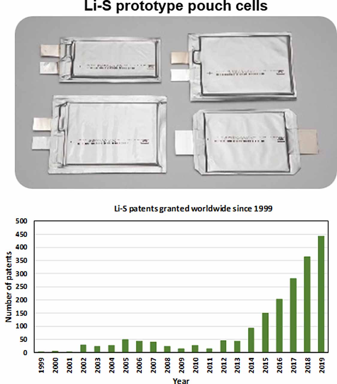
Figure 29. (a) Comparison of the predicted and demonstrated gravimetric energy density of Li–S cells compared to alternative battery technologies and (b) indicative overview of the strengths of a range of commercial or near-commercial battery technologies. Data obtained from a range of published works [4, 189, 190].
Download figure:
Standard image High-resolution image
Figure 29(b) visually demonstrates the necessity to develop a full range of energy storage solutions to account for specific applications as the range of uses for battery technology continues to diversify. The lower volumetric energy densities of Li–S cells will likely result in automotive applications being dominated by Li-ion chemistries in the near future, although safety and charging considerations may result in Li-ion cells being replaced by solid-state batteries for this purpose in the longer term [191]. Further, domestic storage requirements may be satisfied by Na-ion cells. However, figure 29(b) clearly highlights the unique benefits of Li–S as a technology, with early market opportunities arising in applications where the gravimetric energy density is critical. These markets are discussed in detail in earlier sections where HAPS, drones and aerospace are clear targets.
To accelerate the commercialisation of the Li–S chemistry we have outlined a broad range of developments that are required and will require both academic and industrial input. Indeed, each of the recommendations must be considered as part of a wider development strategy due to the intrinsic connection between the components in Li–S cells, which is not necessarily replicated in alternative battery technology. In short, developments in one component of a Li–S cell will not be sufficient to provide a step change in the technology.
Our recommendations for improvements to cathode architectures include targeting technologically relevant electrolyte and S loadings to ensure the translational ability of material development work—we suggest an E/S ratio below 5 μl mg s−1 is required to be comparable to commercial cells, in which the ratio utilised will likely be below 3 μl mg s−1. Further, S loadings of ca. 3–6 mg cm−2 matched by a positive electrode excess of less than 50% are needed. While this S loading can be relatively routinely achieved, the design of a cathode architecture must also consider the 80% volume expansion that occurs upon deposition of Li2S and optimise the porosity to balance the surface and solution reactions with the electrolyte volumes. The incorporation of chalcogenides or the modification of C scaffolds with single atom catalysts or other functional groups is also of interest to inhibit the PS shuttle and promote redox activity in the solution reactions. From a commercialisation perspective, the prospect of freestanding electrodes is extremely attractive and should be considered in the wider context of this multifunctional C architecture. The methods used to infiltrate the cathode with S should also be considered in the wider context of cathode design, with the wetting of the cathode extremely important to maximise the cell energy density.
Of all the components of the cell, the interplay between the anode and electrolyte is perhaps the most crucial to improving cells. In common with all Li–metal/liquid electrolyte cells, an improved fundamental understanding of the mechanisms is required. Further, the identification of additives to inhibit the PS shuttle reaction and drive the Li plating/stripping behaviour towards planar growth should be prioritised. It is clear that should a solid-state protection layer be deployed at the Li-metal anode, a critical conductivity to volume must be achieved. In this work this criterion has been assessed in terms of an E/C ratio, with hybrid polymer–sulfide materials being shown to be the most promising solution to balance the requirements of a protective layer. The development of this protective layer will expand the range of electrolytes that can be considered, which offers the potential to optimise the parameters (viscosity, wettability etc) of the electrolyte. The use of RMs to promote reactions throughout the charge and discharge processes is also considered highly promising; however, there remains significant work to better understand how these additives impact the operation of cells. In all of these instances, the development of in situ and operando experiments to enhance fundamental understanding is crucial. Here, the design of bespoke cells and experiments will be required over the coming years. We strongly recommend that when these advanced cells, housings or experiments are designed they are well detailed in reports to enable experimental replication and development.
The modelling sections in this work outline the potential benefits of a strong link between the experimental and computational communities in Li–S. Molecular-scale modelling provides the opportunity to identify a priori candidate materials to catalyse the PS reactions and inhibit PS shuttling; however, consideration should be given to the need to augment DFT calculations with van der Waals forces when calculating binding and adsorption energies. To date, reports of work at the anode/electrolyte interface are scarce and these should be conducted to enhance our understanding of mechanisms. The development of mesoscale models should be encouraged to optimise cathode design and understand the processes that may extend lifetime, with this work also acting as a bridge between molecular- and microscale modelling. At the continuum level, the existing Li–S literature does not reproduce the experimentally observed spatiotemporal effects. As such, there is a need to rapidly develop these models, moving beyond the Bruggeman correlation and incorporating the microstructural evolution that occurs upon cycling. Naturally, this modelling should be validated against experimental results. To achieve this, there is a clear need to expand the characterisation efforts of both the mechanisms and cell architectures. Here, x-ray methods and multitechnique experiments are very powerful, with operando experiments once more being extremely valuable. To encourage and expand the existing Li–S modelling efforts, we would encourage researchers to provide experimental data sets alongside their results where possible.
Finally, there must be an active effort to accelerate commercially relevant cell engineering, diagnostic and safety work to maintain pace with the rapid developments in other areas. LiSBs are currently an emergent commercial technology, as demonstrated by the sharp increase in patents in recent years. To facilitate this, improvements in state estimation methods are required to develop battery management frameworks and to combine cells at a module and pack level. To date, reports of safety tests and degradation at a commercially relevant scale are extremely limited. While demonstrating progress at a coin cell level is an important step, the scale-up process for Li–S systems is complicated and there is no established correlation to translate the performance of a material from the milliampere hour to ampere hour scale. As such, it is vital that once the potential of a material or component is identified, efforts are made to demonstrate developments beyond the coin cell level. By achieving this, researchers will ensure their work is tested under the most rigorous conditions (low electrolyte loading, reduced N/P ratio, etc) and provide the best opportunity to accelerate the development of Li–S technology as a whole.
Acknowledgments
This work was supported by the Faraday Institution LiSTAR programme (EP/S003053/1, Grant FIRG014). PRS acknowledges the Royal Academy of Engineering for the Chair in Emerging Technologies (CiET1718/59). JBR and PRS would like to sincerely thank Ms Hannah Tipple for her assistance in administering in the LiSTAR programme.