Abstract
Here we show the feasibility of a novel high energy density battery with a Li anode and a MCl2 (M = Fe, Co, Ni, Cu, and Zn) aqueous cathode separated by a water-stable NASICON-type lithium-ion conducting solid electrolyte of Li1.4Al0.4Ge0.2Ti1.4(PO4)3 (LAGTP). The Li/MCl2 (M = Co, Ni, and Zn) aqueous solution with LiCl cells were successfully charged and discharged. In contrast, the Li/MCl2 (M = Fe and Cu) cells were discharged, but they could not be charged, because FeCl2 and CuCl2 reacted with lithium-ions to produce an insoluble compound. The Li/CoCl2 and Li/NiCl2 cells showed discharge cathode capacities of 326 and 412 mAh g−1 at 60°C and 4.0 m A cm−2, respectively, which correspond to 78 and 100% to the theoretical capacity, respectively. The estimated specific energy densities calculated using the mass of cell components with a 0.1 mm thick LAGTP separator (except the packaging) were 617 and 670 Wh kg−1 for the Li/CoCl2 and Li/NiCl2 cells, respectively, which are approximately two times higher than those for conventional lithium-ion batteries.
Export citation and abstract BibTeX RIS

This is an open access article distributed under the terms of the Creative Commons Attribution 4.0 License (CC BY, http://creativecommons.org/licenses/by/4.0/), which permits unrestricted reuse of the work in any medium, provided the original work is properly cited.
Electrical vehicles (EVs) are considered to reduce CO2 emissions and the consumption of fossil fuels because the total energy conversation efficiency of batteries is higher than that of internal combustion (IC) engines.1 However, the driving range of commercialized EVs with the current lithium-ion batteries is considerably lower than that of vehicles with IC engines because the specific energy density for the lithium-ion battery is too low compared with the IC engine.2 The calculated specific energy density of a gasoline engine for automotive applications is estimated to be around 1700 Wh kg−1, determined using the reaction heat of gasoline and a tank to wheel efficiency of 12.6%.2 The theoretical specific mass and volume energy densities calculated for a lithium-ion battery based on a carbon anode and a LiCoO2 based cathode are 387 Wh kg−1 and 1015 Wh dm−3, respectively,3,4 the former of which is around one fourth of that for the IC engine. Many types of battery systems beyond lithium-ion batteries have been proposed, such as lithium-sulfur and lithium-air rechargeable batteries.3,5–9 The lithium-sulfur battery is a very attractive battery system because of its high theoretical energy density (ca. 2600 Wh kg−1 and 2199 Wh dm−3).3,5 However, even after several decades' research and development, the lithium-sulfur battery has still not reached mass commercialization. Several problems inherent in the cell chemistry remain, such as poor electrode rechargeability and limited rate capability due to the insulative nature of sulfur and the solid reaction products, and fast capacity fade due to the generation of various soluble polysulfide intermediates. The calculated energy densities for the non-aqueous lithium-air cell are as high as 3505 Wh kg−1 and 3436 Wh dm−3.3 The specific mass energy density is quite attractive for the power source in EVs and interest has expanded rapidly in recent years. Although significant progress has been made by many researchers, serious problems remain to be solved, such as decomposition of the non-aqueous electrolyte by the reaction product of the super oxide, reduction of the carbon electrode during the charging process, and the blocking of H2O and CO2 present in air. The concept of the rechargeable aqueous lithium-air cell was proposed by Visco et al.10 in 2004, based on a lithium anode, a water-stable NASICON-type lithium conducting solid electrolyte of Li1+xAlxTi1-x(PO4)3 (LATP), an aqueous electrolyte, and a carbon air electrode with a catalyst. Some of the serious problems for non-aqueous lithium-air batteries are not applicable to the aqueous system; however, the calculated energy densities for the aqueous system (1897 Wh kg−1 and 1991 Wh dm−3) are lower than those for the non-aqueous system, because water is active material for the cell reaction. The reduction of the thickness of LATP is challengeable. As such, an aqueous lithium-air cell with a high specific energy density has not yet been demonstrated.9
Goodenough and co-workers11 and Zhou and co-workers12 proposed a new concept of an aqueous cathode for next-generation alkali-ion batteries. The cell proposed by Goodenough and co-workers consists of a water-stable LATP separator, a water soluble redox couple cathode, Fe(CN)63−/Fe(CN)64−, and a lithium anode. However, the theoretical specific energy density of the proposed system was 392 Wh kg−1, which is comparable to that of the lithium-ion battery. A similar concept was reported by Byon and co-workers13 using a triiodide/iodide redox couple in an aqueous cathode. This system showed an excellent rate capability, although the theoretical specific energy density of this system was comparable with those of the Fe(CN)63−/Fe(CN)64− couple. Polyplus Battery Company14 developed aqueous electrolyte lithium sulfur batteries, which consist of a water stable LATP separator, a water soluble lithium sulfide, and lithium metal anode. The theoretical energy density is as high as 2300 Wh kg−1. The delivered capacity corresponded to a value that is higher than 700 mAh per gram of dissolved sulfur over at least 2 cycles. A lithium anode and liquid cathode couples have potential for the development of rechargeable batteries with high specific energy density because there is no binder or conductive additive in the electrodes. Here we demonstrate the feasibility of a high specific energy density aqueous lithium rechargeable battery with an aqueous cathode of MCl2 (M = Fe, Co, Ni, Cu and Zn) using a high lithium-ion conductivity solid electrolyte of Li1.4Al0.4Ge0.2Ti1.4(PO4)3-epoxy resin film (LAGTP)15 as the separator between the lithium anode and the aqueous cathode.
Experimental
LAGTP films were prepared by a tape-casting method.15 The Li1.4Al0.4Ge0.2Ti1.4(PO4)3 powers were prepared by the sol-gel method using citric acid. Briefly, stoichiometric amounts of Ti(OCH4H9)4 and Ge(OC2H5)4 were dissolved in ethylene glycol, added to a 0.2M aqueous solution of citric acid, and then stirred continuously with a magnetic stirrer at 120°C for 12 h to obtain a homogeneous solution. After preparation of the gel was completed, stoichiometric amounts of LiNO3, Al(NO3)3·9H2O and NH4H2PO4 were added to the gel solution. After a homogenous solution was formed, the gel was kept at 170°C for 4 h to allow water to evaporate and promote esterification and polymerization. The gel was then heated at 500°C for 4 h to complete decomposition of the nitrate and organic compounds. The black colored product with residual carbonate was ground to a fine power with an agate mortar and pestle before sintering at 900°C for 7 h. The LAGTP powder was dispersed in a mixed solution of ethanol and toluene with polyvinyl alcohol as a binder and butyl benzyl phthalate as a plasticizer, and the slurry was ball-milled using a high speed mechanical mill (Fritsch Planetary Micro Mill PULVERISETTE 7). The slurry was tape-cast and then sintered at 900°C for 7 h. The tape-cast LAGTP-epoxy resin composite film was prepared by dropping a mixed solution of 1 M 1,3-phenylenediamine and 2M 2,2-bis(d-glycidyloyphenyl) propane in tetrahydrofuran (THF). The film was then heated at 150°C for 24 h.
The cell performance was measured using an in-house-built Swagelok-type cell. Figure 1 shows a schematic diagram of the test cell, which consists of a lithium metal anode, a Li(FSO2)2N (LiFSI)-tetraethylene glycol dimethyl ether (G4) (1:2 molar ratio)-50 vol. % 1,3 dioxolane (DOL) interlayer, LAGTP, an aqueous MCl2 solution, and a current collector composed of M. A water-stable and water-impermeable tape-cast LAGTP film with epoxy resin (ca. 0.3 mm thick) was used as the protective layer between lithium metal and the aqueous solution. A H-type cell15 was used to the water permeation through the tape-cast LAGTP film with epoxy resin, where the saturated LiCl aqueous solution was on one side of the cell and distilled water on the other side. The chloride-ion content in the distilled water side was measured with respect to the time using a chloride-ion meter (Kasahara CL-5Z Japn). The (LiFSI-2G4)-50 vol. % DOL electrolyte was used as an interlayer between lithium and LAGTP to protect from direct contact between lithium and LAGTP, because LAGTP is unstable in contact with lithium metal.16 The Li/(LiFSI-2G4)-50 vol. % DOL electrolyte was reported to supress lithium dendrite formation at room temperature and high current density.17 A 200 μm lithium foil was used as the anode. The contact area of the lithium anode with the interlayer electrolyte was 1.13 cm2. The thickness and diameter of the LAGTP-epoxy solid electrolyte was ca. 300 μm and 1.6 cm, respectively and the contact area of it with the interlayer electrolyte and the catholyte was 1.13 cm2. The area of the M current collector with the catholyte was 0.98 cm2. The current density was measured based on the M current collector. The lithium anode side of the Li/interlayer/LAGTP cell was assembled in a glove box under Ar and the aqueous cathode was then charged outside the glove box. A pouch-type cell was used for some cells with a small amount of the catholyte, where 4M LiFSI in dimethoxyethane (DME)18 was used as the interlayer between lithium metal and LAGTP, because a plastic film used was soluble in DOL. The lithium anode, interlayer, and LAGTP were sealed with the plastic film with a 1 cm diameter window.
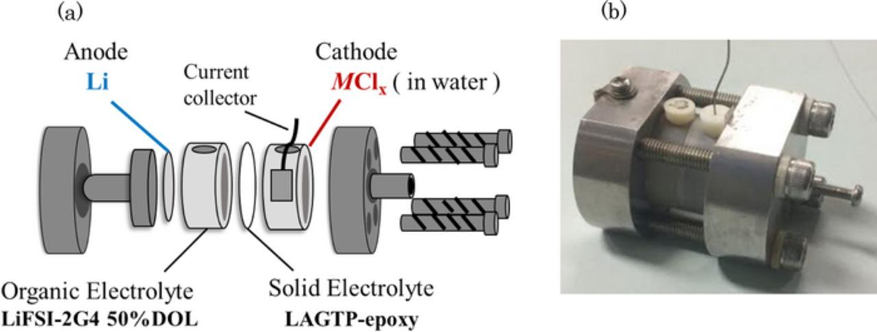
Figure 1. Schematic diagram of the test cell and photograph of the Li/(LiFSI-2G4)-50 vol. % DOL/LAGTP/saturated MCl2 and LiCl aqueous solution (1:1 vol. ratio)/M cell.
AC impedance spectroscopy measurements of the cells were performed using a frequency response analyzer (Solartron 1260) with an electrochemical interface (Solartron S1 1287) in the frequency range of 0.1 Hz to 1 M Hz. Zplot software was employed for the data analysis. The electrode potentials at a constant current drain were measured using a multichannel potentio-galvanostat (Bio-Logic Science Instruments VMPX) and cyclic voltammetry was conducted using a potentio-galvanostat (Solartron 1287). X-ray diffraction (XRD) patterns were obtained using a diffractometer with a rotating copper cathode (Rigaku Rint 2500).
Results and Discussion
The stability of LAGTP in the saturated MCl2 aqueous solution is an indispensable requirement for the separator between the lithium electrode and aqueous catholyte. Shimonishi et al.19 reported that a NASICON-type lithium-ion conducting solid electrolyte was stable in aqueous acetic acid saturated with lithium acetate, of which the pH was ca. 3. The impedance profiles of a Pt/mixture of the saturated CoCl2 and LiCl aqueous solutions (1:1 vol. ratio)/LAGTP/mixture of the saturated CoCl2 and LiCl aqueous solutions (1:1 vol. ratio)/Pt cell are shown as a function of the storage period in Figure 2a. The impedance profiles show a semicircle, which is attributed to the grain boundary resistance.20 No change in the impedance profiles of the cell was observed for three weeks. Figure 2b shows the temperature dependence of the electrical conductivity for LAGTP. The total conductivities (bulk and gain boundary) of LAGTP at 25 and 60°C were 6.4 × 10⁻⁴ and 2 × 10⁻³ S cm−1, respectively.
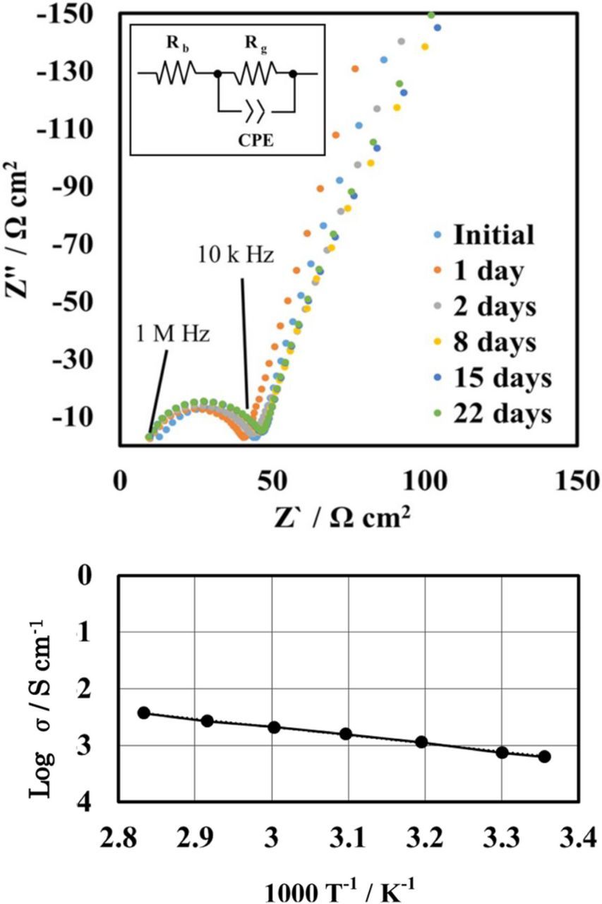
Figure 2. (a) Impedance profiles of the Pt/saturated CoCl2 and LiCl aqueous solution (1:1 vol. ratio) /LAGTP-3 wt% epoxy resin/saturated CoCl2 and LiCl aqueous solution (1:1 vol. ratio)/Pt cell measured at 25°C for various storage periods and (b) temperature dependence of the electrical conductivity of LAGTP-3wt%epoxy resin.
The electrode reactions for the Li/aqueous MCl2 solution cell can be written as follows:
![Equation ([1])](https://content.cld.iop.org/journals/1945-7111/164/9/A1958/revision1/d0001.gif)
![Equation ([2])](https://content.cld.iop.org/journals/1945-7111/164/9/A1958/revision1/d0002.gif)
![Equation ([3])](https://content.cld.iop.org/journals/1945-7111/164/9/A1958/revision1/d0003.gif)
![Equation ([4])](https://content.cld.iop.org/journals/1945-7111/164/9/A1958/revision1/d0004.gif)
![Equation ([5])](https://content.cld.iop.org/journals/1945-7111/164/9/A1958/revision1/d0005.gif)
where (s), (aq) and (g) denote solid. aqueous and gas phases, respectively. The requirement for the aqueous cathode redox couples in aqueous lithium batteries are as follows: (1) a high theoretical specific capacity, (2) a suitable redox potential to avoid the electrolysis of water, (3) stability of the reaction products in the aqueous cathode to achieve a low self-discharge rate, and (4) stability of the water-stable lithium-ion conducting solid electrolyte in the saturated aqueous solution of the cathode materials to achieve a high specific energy density. The transition metal chlorides, MCl2 (M = Fe, Co, Ni, Cu, and Zn,), are suitable candidates for the aqueous lithium battery because the solubility of MCl2 in water is high and the theoretical specific energy density of the Li/MCl2 couples are more than two times higher than that of the lithium-ion cell, as shown in Table I. The problem for the aqueous lithium cell is a competitive hydrogen evolution Reaction 3 during the discharge processes. Table I shows the pH values and M2+/M electrode potentials in saturated MCl2 aqueous solutions along with the hydrogen evolution potentials on the M electrode, including the over-potentials for the hydrogen evolution reaction at 1.0 mA cm−2.21 The metal ion reduction potentials in saturated MCl2 aqueous solutions are slightly higher than the hydrogen reduction potential on the corresponding metals, including the hydrogen over-potential.
Table I. Metal deposition and hydrogen evolution potential and theoretical specific energy density of lithium/metal chloride couples.
| Metal deposition potential | Hydrogen evolution potential | Energy density | |||
|---|---|---|---|---|---|
| Chloride | pH* | vs. NHE (V)** | vs. NHE (V)*** | Wh kg−1 Wh dm−3 | |
| FeCl2 | 2.1 | −0.43 | −0.464 | 991 | 1963 |
| CoCl2 | 3.8 | −0.27 | −0.45 | 1018 | 2101 |
| NiCl2 | 3.7 | −0.20 | −0.43 | 1047 | 2340 |
| CuCl2 | 0.8 | 0.14 | −0.25 | 1190 | 2688 |
| ZnCl2 | 2.3 | −0.74 | −0.83 | 813 | 1677 |
*pH values for metal chloride saturated aqueous solutions. **Metal chloride saturated aqueous solution. ***Including the hydrogen evolution overpotential at 1.0 mA cm−2 by Stanojevic et al.20
To obtain the theoretical specific capacity of the Li/MCl2 cell, the catholyte should have more MCl2 than the solubility limit at the fully charged state because water is not active for the cathode reaction. Figure 3 shows the charge and discharge performance of the Li/(LiFSI-2G4)-50 vol.% DOL/LAGTP/MCl2 (M = Fe, Co, Ni, Cu and Zn) aqueous solution /M cell at 25°C and 1.0 mA cm−2 for 10 h under polarization. The CoCl2, NiCl2 and ZnCl2 catholytes were mixtures of the saturated MCl2 (M = Co, Ni, and Zn) and LiCl aqueous solution (1:1 vol. ratio) (abridged as saturated MCl2-LiCl aqueous solution), whereas the FeCl2 and CuCl2 catholytes had no LiCl, because the saturated FeCl2 and CuCl2 aqueous solutions precipitated a solid by the addition of LiCl, as shown in the insets of Figures 2a and 2d. The OCVs are in good agreement with those calculated using the potential differences of M2+/M and Li+/Li (Eo). The OCVs were recorded to be 2.58 V for Li/FeCl2 (Eo = 2.60 V), 2.73 V for Li/CoCl2 (Eo = 2.77 V), 2.80 V for Li/NiCl2 (Eo = 2.81), 3.41 V for Li/CuCl2 (Eo = 3.39 V), and 2.28 V for Li/ZnCl2 (Eo = 2.28 V). The Li/MCl2 (M = Co, Ni, and Zn) cells showed steady charge and discharge voltages for 10 h polarization, where the discharge depth was 11% for Li/CoCl2, 9% for Li/NiCl2, and 5% for Li/ZnCl2. The Li/MCl2 (M = Fe and Cu) cells showed a steady discharge cell voltage, where the discharge depths for Li/FeCl2 and Li/CuCl2 were 10%. However, the cell voltages during the charge processes for both cells were abruptly increased after polarization for 30 min at 1.0 mA cm−2. The Li+ ions that move from the Li anode to the catholyte during the discharge process may react with FeCl2 and CuCl2 to form an aqueous-insoluble compound. The precipitates in the CuCl2-LiCl system were identified as a mixture of LiCuCl3(H2O)222 and unknown phases from the XRD results, but the precipitates in the FeCl2-LiCl system were not identified; these may be new unknown compounds in the FeCl2-LiCl-H2O system, as observed for the CuCl2-LiCl-H2O system. The stability of the reaction products of Co, Ni and Zn in the saturated MCl2 (M = Co, Ni, and Zn)-LiCl aqueous solution is essential for rechargeable batteries. The coulombic efficiencies for the deposition and dissolution of Co, Ni, and Zn on the Pt electrode were measured as a function of storage period for the deposited metals; Co and Ni were stable in the saturated MCl2-LiCl (M = Co and Ni) aqueous solutions and Zn was dissolved into the saturated ZnCl2-LiCl aqueous solution at a dissolution rate of ca. 2 mg day−1 cm−2. The Li/ZnCl2 cell may thus be limited for practical applications.
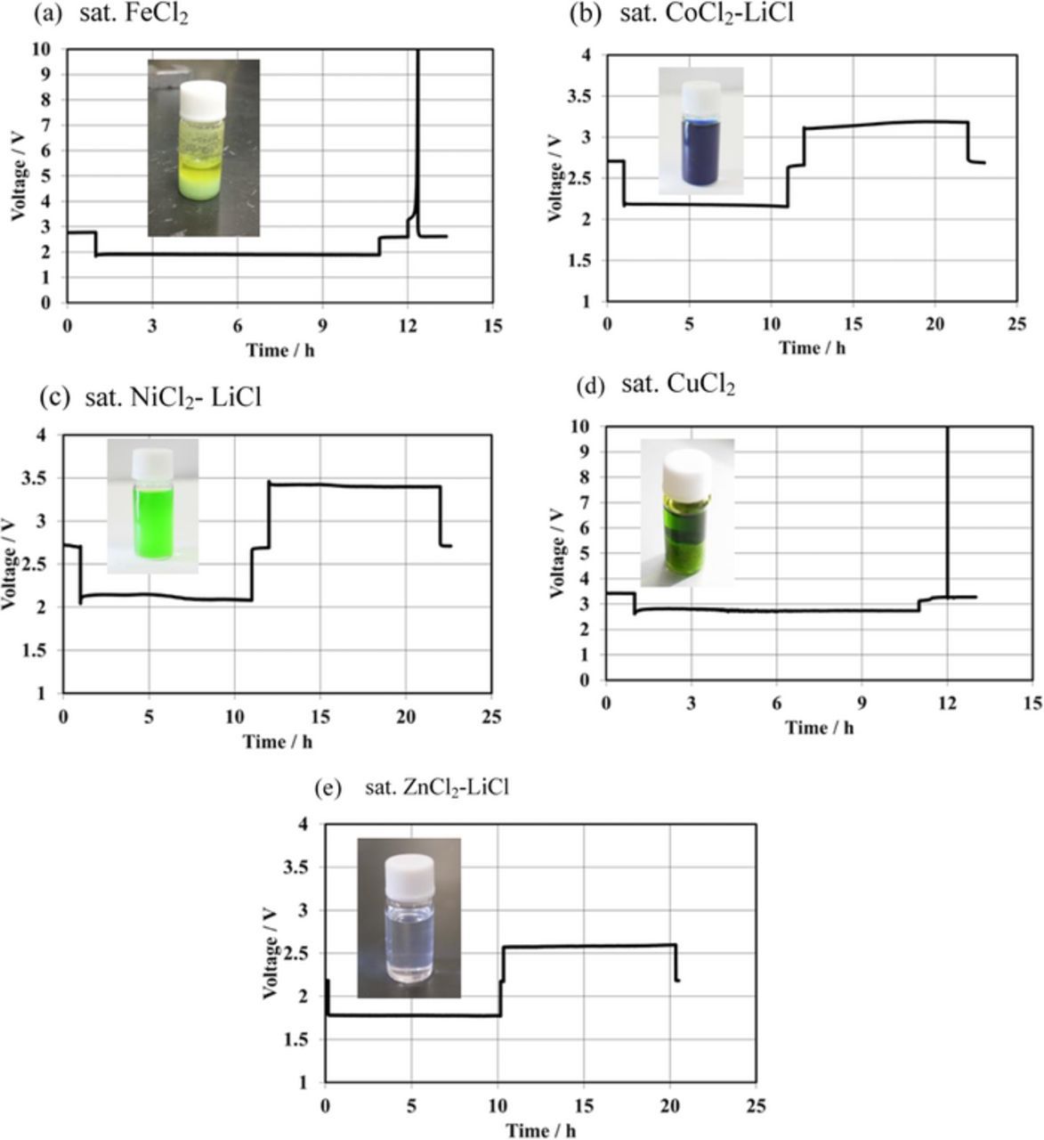
Figure 3. First cycle charge and discharge performance of the Li/(LiFSI-2G4)-50 vol% DOL/LAGTP/saturated MCl2-LiCl aqueous solution/M cell at 1.0 mA cm−2 and 25°C. (a) saturated FeCl2 aqueous solution, (b) saturated CoCl2 and LiCl aqueous soltuon (1:1 vol. ratio). (c) saturated NiCl2 and LiCl aqueous solution (1:1 vol. ratio), (d) saturated CuCl2 aqueous solution, and (e) saturated ZnCl2 and LiCl aqueous solution (1:1 vol. ratio).
Figures 4a and 4b show the deep discharge and charge behavior for the Li/(LiFSI-2G4)-50 vol. % DOL/LAGTP/saturated MCl2-LiCl aqueous solution/M (M = Co and Ni) cells at 4 mA cm−2 and 60°C, respectively, where the cells were operated at a high temperature and high current density. These cells showed two-step discharge plateaus; the first step discharge plateau could be explained by M2+ reduction to M and the second plateau by the hydrogen evolution reaction, because the cells could be discharged over the calculated capacity of CoCl2 and NiCl2 in the catholytes. The hydrogen evolution reaction was observed after reduction of ca. 80% Co2+ and 100% Ni2+. The higher utilization of NiCl2 than that of CoCl2 may be due to the large potential difference for the metal deposition and hydrogen evolution reactions, as shown in Table I. The charging curves also revealed two-step cell voltage profiles for these cells. The capacities of the first plateaus during the charge process corresponded to those of the second discharge steps in the discharge curves. The cells were gastight and the evolved hydrogen gas was stored in the cathode chamber. The hydrogen reduction reaction proceeded at potentials higher than those of the metal dissolution reactions. These phenomena could be explained by hydrogen gas covering the metal electrode, so that the metal dissolution reactions were blocked. Two-step discharge profiles were also observed for the Li/0.2 M MCl2 (M = Fe, Co, Ni, and Cu) cells at 1.0 mA cm−2 and 25°C. The Li/ZnCl2 cell did not show clear evidence for hydrogen evolution in the discharge curve. Cyclic voltammograms (CV) for metal electrodeposition on platinum in the saturated MCl2 (M = Co, Ni, and Zn)-LiCl aqueous solutions showed no clear evidence for the hydrogen evolution reaction. The cathode side can be operated in the ambient atmosphere, because the catholyte is acid as lead-acid batteries. However, sealed system is more acceptable for the consumer use, because the mists of electrolyte do not diffuse into atmosphere. The hydrogen evolution reaction in the deep discharge is a serious problem for the sealed aqueous Li/MCl2 batteries.
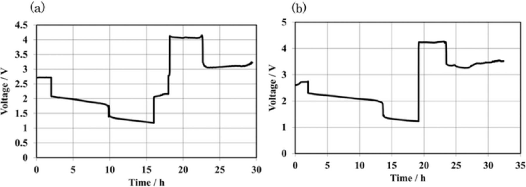
Figure 4. Deep charge and discharge performance for the Li/(LiFSI-2G4)-50 vol. % DOL/LAGTP/saturated MCl2 and LiCl aqueous solution (1:1 vol. ratio)/M (M = Co and Ni) cells at 4.0 mA cm2 and 60°C. (a) M = Co (0.097 g) and (b) M = Ni (0.111 g).
The specific energy density of the cell with a solid cathode is generally dependent on the area specific capacity23 [product of the specific capacity per gram of the active material (mAh g−1) and the active material loading per unit area (g cm−2)]. Li/aqueous liquid MCl2 (M = Co, and Ni) cells are not expected to exhibit dependence of cell performance on the charged amount of MCl2 in the catholyte, because the diffusion of ions in the liquid catholyte are significantly higher than that in solid cathodes. The diffusion constant of lithium ions in Li0.65CoO2 was reported to be 9.8 × 10⁻⁸ cm2 s−1 at 25°C,24 while that of lithium ions in a liquid electrolyte is four orders higher than that in solids.25 Figure 5a shows the discharge performance of Li/NiCl2 with different amounts of NiCl2 at 4.0 mA cm−2 and 60°C. The observed specific capacity of 413 mAh g−1 for the Li/saturated NiCl2-LiCl aqueous solution cell with 0.222 g of NiCl2 (area capacity: 94 mAh cm−2) is comparable to that of 407 mAh g−1 for the cell with 0.111 g of NiCl2 (area capacity: 47 mAh cm−2). The effect of the excess amount of CoCl2 in the catholyte was also examined. Figure 5b shows the discharge performance of a pouch-type Li/CoCl2 cell at 0.5 mA cm−2 and 25°C as a function of the amount of CoCl2, where an excess amount of the solid CoCl2 was added into the saturated CoCl2-LiCl aqueous solution. The specific capacity of the Li/CoCl2 cell was increased with the amount of CoCl2 in the catholyte. Specific capacities of 368 and 281 mAh g−1 were achieved for the cells with 24.2 mg and 12.1 mg of CoCl2, respectively, which correspond to 89 and 68% to the theoretical capacity.
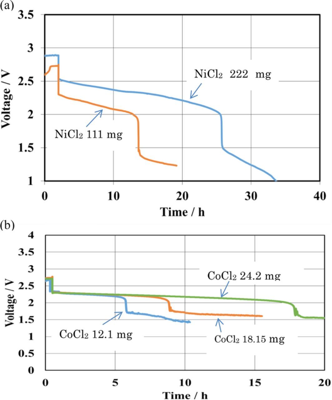
Figure 5. Discharge curves of Li/MCl2 cells for various amounts of MCl2 in the catholyte (M = Co and Ni). (a) Li/(LiFSI-2G4/LAGTP/saturated NiCl2 and LiCl aqueous solution (1:1 vol. ratio)/Ni cells)-50 vol. % DOL at 4 mA cm−2 and 60°C and (b) Li/Li/4M LiFSI in DME/LAGTP/CoCl2 and LiCl aqueous solution (1:1 vol, ratio)/Co cells at 0.5 mA cm−2 and 25°C.
The charge and discharge cyclic performance for the Li/MCl2 cells (M = Co and Ni) are shown in Figures 6. Excellent cyclic performance was observed for these cells at 1.0 mA cm−2 and 25°C, where the theoretical area capacity was 98 mAh cm−2 and 9.8 mAh cm−2 was cycled. The Li/MCl2 (M = Co and Ni) cells also showed good cyclic performance at a deep charge and discharge of 4.0 mA cm−2 at 60°C, where the theoretical area capacity and utilization of the active material were 31.3 mAh cm−2 and 70%, for the Li/CoCl2 cell and 40 mAh cm−2 and 90% for the Li/NiCl2 cell, respectively. The high power density is an important requirement for the EV batteries. Current density vs. cell potential curves for the Li/(LiFSI-2G4)-50 vol.% DOL/LAGTP/saturated CoCl2-LiCl aqueous solution/Co cell at 25°C showed a linearly decrease of the cell voltage with an increase in current density as shown in Figure 7a. The cell impedance profile (see Fig. 7b) shows a large contribution of the LAGTP26 and interlayer electrolyte resistances. To improve the cell performance, the thickness of LAGTP and the interlayer electrolyte of (LiFSI-2G4)-50 vol.% DOL should be reduced, where the thicknesses of inter layer electrolyte and LAGTP were around 1.0 mm and 0.3 mm, respectively.
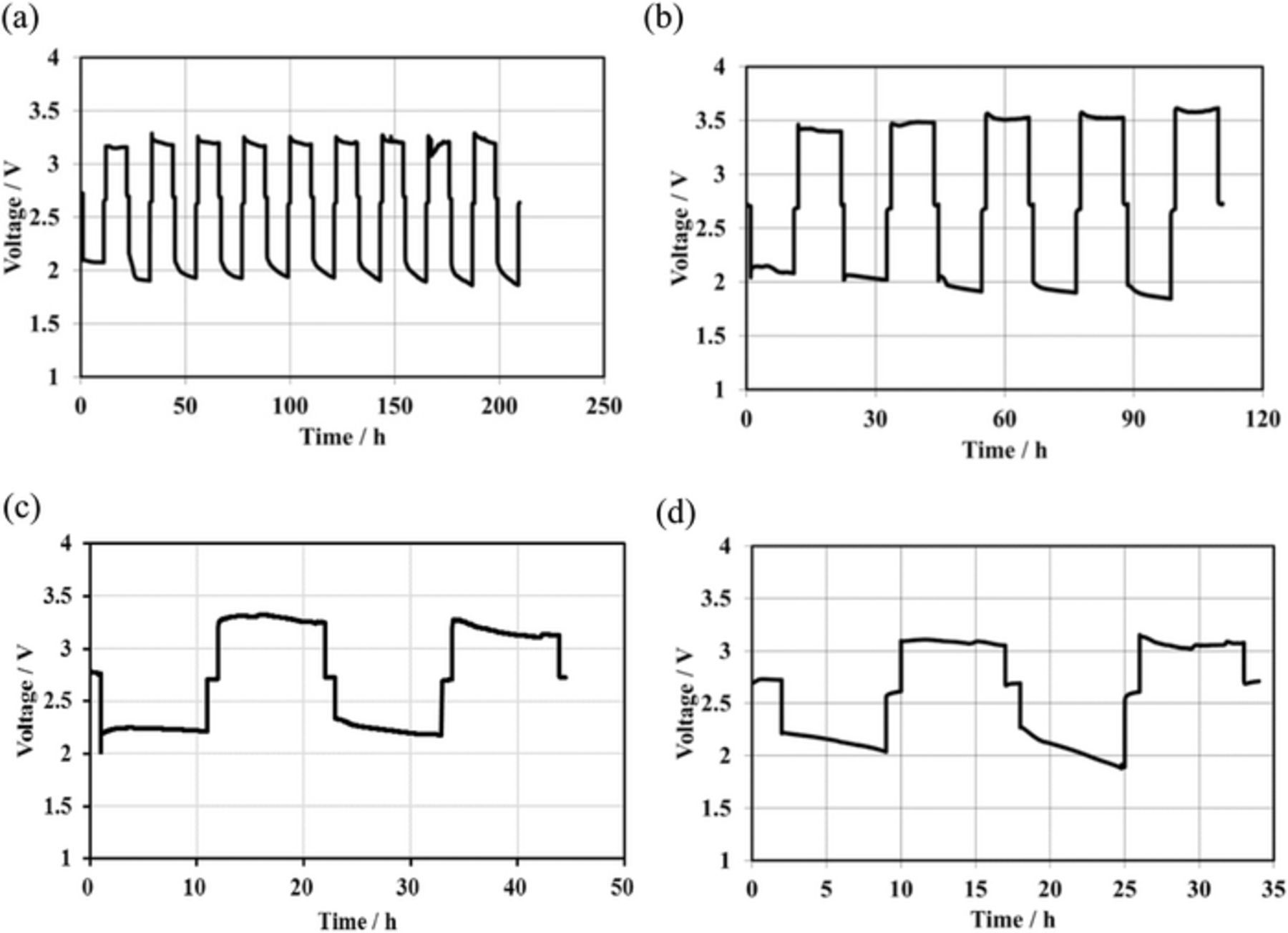
Figure 6. Cycle performance for Li/(LiFSI-2G4)-50 vol. % DOL/LAGTP/saturated MCl2 and LiCl aqueous solution (1:1 vol. ratio)/M. (a) M = Co at 1.0 mA cm2 and 25°C, (b) M = Ni at 1.0 mA cm−2 and 25°C, (c) M = Co at 4.0 mA cm−2 and 60°C, and (d) M = Ni at 4.0 mA cm2 and 60°C.
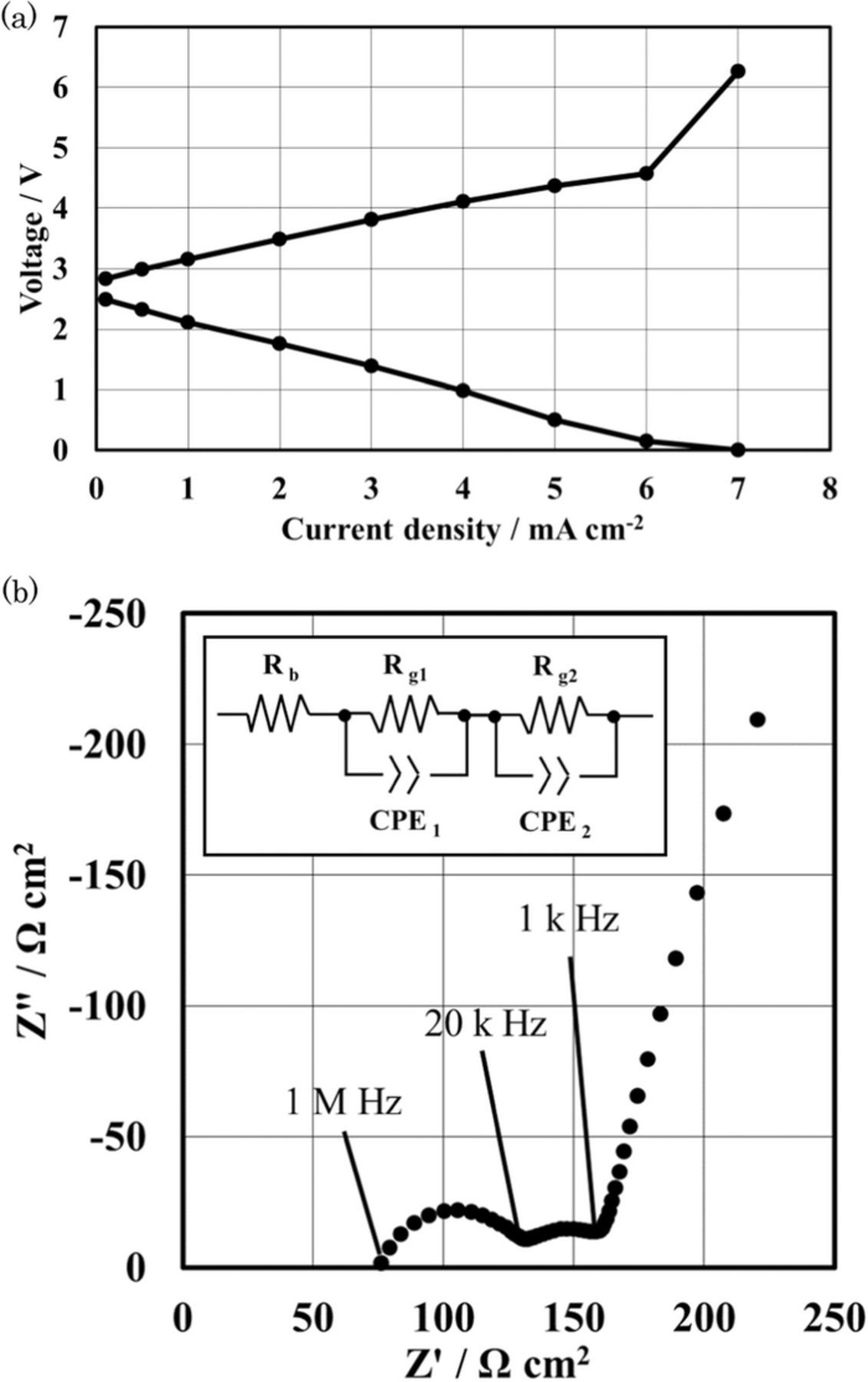
Figure 7. (a) Current density vs. cell voltage curves for the Li/(LiFSI-2G4)-50 vol. % DOL/LAGTP/saturated CoCl2 and LiCl aqueous solution (1:1 vol. ratio)/Co cell at 25°C, where the cell voltages were recorded after polarization for 1 h. (b) Cell impedance for Li/(LiFSI-2G4)-50 vol. % DOL/LAGTP/saturated CoCl2 and LiCl aqueous solution (1:1 vol. ratio)/Co cell at 25°C, where the thicknesses of LAGTP and interlayer were around 0.3 mm and 1.0 mm, respectively.
Park et al.27 reported the dependence of the specific energy density on the area specific capacity of Li-ion, Li-S and Li-air batteries, where the specific energy density of a Li-ion battery with a LiCoO2 cathode and carbon anode became almost saturated at 380 Wh kg−1 at 6 mAh cm−2.The cell specific energy densities of the Li/CoCl2 and Li/NiCl2 cells were calculated based on the mass of the components (except the packaging) and were compared with that calculated by Park et al. for a C/LiCoO2 cell, and the results are shown in Figure 8 as a function of the specific area capacity, where the thickness of the key LAGTP material for the calculation was 0.1 mm, the ratio of cathode active material in electrode was 0.9. and the lithium anode capacity was two times greater than that of the cathode active material. The 0.1 mm thick LAGTP film exhibits an acceptable 3-point bending strength of 120 MPa.14 The specific energy densities of Li/CoCl2 and Li/NiCl2 at an area capacity of 200 mAh cm−2 are 617 and 670 Wh kg−1, respectively.
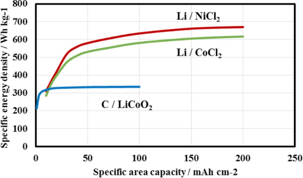
Figure 8. Dependence of specific energy density on the specific area capacity for Li/CoCl2, Li/NiCl2 and C/LiCoO2, where the respective utilization of CoCl2 and NiCl2 of 78 and 100% was used for the calculations.
Conclusions
We have proposed a novel high energy density rechargeable battery with a lithium metal anode and a MCl2 (M = Fe, Co, Ni, Cu, and Zn) aqueous cathode. The anode and catholyte were separated by a high lithium-ion conducting solid electrolyte of Li1.4Al0.4Ge0.2Ti1.4(PO4)3. Flat discharge and charge curves were observed at 1.0 mA cm−2 and room temperature for the Li/MCl2 (M = Co, Ni, and Zn) cells. The reaction products of Co and Ni were stable in the saturated MCl2-LiCl (M = Co and Ni) aqueous solutions, while that of Zn was unstable in the saturated ZnCl2-LiCl aqueous solution. The cell performance with the lithium anode and liquid aqueous cathode showed no dependence on the charged amount of MCl2. The Li/NiCl2 cell showed excellent performance with a specific area capacity as high as 94 mAh cm−2. The specific energy densities of Li/CoCl2 and Li/NiCl2 at an area capacity of 200 mAh cm−2 are 617 and 670 Wh kg−1, respectively, which are around 2 times higher than that of a conventional Li-ion battery (328 Wh kg−1). We could thus expect that the driving range for EVs with the Li/MCl2 (M = Co and Ni) cell would be acceptable.