Abstract
Phosphor-in-glass (PiG) is a mixture of a transparent glass and ceramic phosphors and has been recently commercialized for its various advantages as an inorganic color converter for white light emitting diodes (wLEDs). Since the successful demonstration of the wLED and its improved stability over the conventional phosphors in silicon or organic resins, extensive studies have been reported to improve its color conversion and resultant LED properties, such as luminescence efficacy, chromaticity, correlated color temperature and color gamut, as well as its long term stability. Various attempts have also been made to fabricate a PiG structure and to extend its applications. This study reviews the recent progress of PiG and discusses various approaches that have been proposed to overcome the technical issues related to PiG.
Export citation and abstract BibTeX RIS

This is an open access article distributed under the terms of the Creative Commons Attribution 4.0 License (CC BY, http://creativecommons.org/licenses/by/4.0/), which permits unrestricted reuse of the work in any medium, provided the original work is properly cited.
White light emitting diodes (wLEDs) have become a conventional light source these days due to their high power-efficiency and long term stability compared to traditional fluorescence lamps. wLEDs are normally composed of an InGaN based blue LED chip and a Y3Al5O12:Ce3+ (YAG:Ce3+) yellow phosphor which is embedded within organic binders or silicone resins (Fig. 1). Although organic resins are good for mixing with ceramic phosphor powders and can easily be mounted on top of the blue LED chip in a paste form, they have weak UV, thermal and chemical stability which turns their color into brown or yellow and deteriorates the color quality of the LED in the long term.1–4 The viscosity of the organic resin also creates difficulties for the homogeneous distribution of phosphor powders within the paste, which produces a blurring behavior in the LED light or a wide variation of resultant color coordinates with the same production conditions (binning). However, recent development of high power and high brightness (HP/HB) wLEDs which can reach the chip temperature above 150°C,1–4 requires highly stable color converters to further extend the LED applications to areas such as automotive headlamps, lighting and displays.
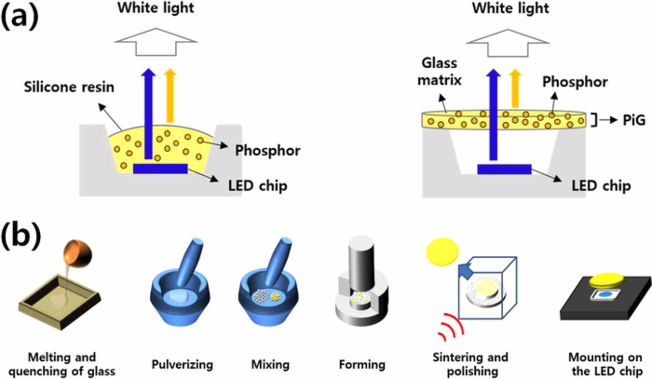
Figure 1. (a) Schematic diagram of conventional wLED with silicone resin (left) and PiG (right) and (b) conventional fabrication process of PiG.
In order to overcome the inherent problems of organic resins, various inorganic color converters have been proposed, such as phosphor ceramics,5–7 phosphor glass ceramics8–12 and bulk glass phosphors.13–16 Phosphor ceramic (or ceramic phosphor plate, "CPP") is a ceramic plate which has been sintered with ceramic phosphor powders, and thus can guarantee the high thermal stability and quantum efficiency of phosphors.5–7 However, it is hard to fabricate a sintered ceramic plate as there are few phosphor systems which can be sintered in a plate form and it requires high pressure and high temperature demanding high production cost. Phosphor glass ceramic (PGC) is a glass which has been crystallized to form a phosphor phase such as YAG:Ce3+.8–12 However, it is difficult to control the phosphor crystallinity within a glass phase and there are few systems which can be vitrified. Bulk glass phosphors which have active ions such as rare earth ions or transition metals within the glass network have been proposed but they suffered from their very low quantum efficiency.13–16 Recently, glasses with quantum dots such as CdSe/CdS17,18 have been suggested and successfully demonstrated in a wLED with improved stability, but they still showed a limited quantum yield of less than 25%. Glasses with CsPbX3 perovskite quantum dots19,20 have also made a wLED with a high quantum yield of up to 80%, but they still showed weak thermal stability which is hardly acceptable for commercial applications.
A more reasonable and practical solution for inorganic HP/HB LED color converters has been achieved with phosphor in glass (PiG). PiG is a simple mixture of a transparent glass and phosphor powders which are sintered together at a temperature lower than 800°C using the viscous flow of the glass matrix as depicted in Fig. 1. Replacement of silicon or organic resin with an inorganic transparent glass improves the thermal and chemical stability while maintaining the color conversion efficiency of the conventional phosphors. Compared to CPP which requires 100% phosphor powders and high temperature operation, PiG uses a smaller amount of phosphors and a low sintering temperature, which thus lowers production cost. Moreover, although the CPP or PGC can be applied only to the limited phosphor systems, various commercial phosphor powders can be used depending on the glass matrix, and the optical properties of the wLED, such as the color coordinate, co-related color temperature (CCT), color rendering index (CRI), color gamut and luminous efficacy (LE), can be easily controlled by the mixing phosphors, the mixing ratio and the PiG thickness. Thus, along with CPP, PiG has been recently commercialized and applied to high power wLED applications such as automotive headlamps.
The study of PiG has been led by glass manufacturing companies such as Nippon Electric Glass (NEG)21,22 and Schott.23 NEG demonstrated highly improved stability of sulfide phosphors with a glass matrix, but they used a high sintering temperature of ∼1,000°C. Allen et al.24 introduced the idea of embedding phosphors with a PbO-SiO2 based glass system with limited conversion efficiency. Nass et al.23 demonstrated for the first time the feasibility of PiG by showing the PiG plate with various phosphors with a wafer shape with high thermal and color stability. However, they also used PbO based glass which has been restricted by environmental regulations. The first practical demonstration of PiG using a Pb-free silicate glass matrix was reported by Lee et al.25 They used a SiO2-B2O3-RO (R = Ba, Zn) glass system that had a low sintering temperature of 750°C and showed that the color coordination of a wLED can be easily controlled by a simple variation of the glass to phosphor ratio or the thickness as exhibited in Fig. 2. Extensive studies followed to improve color conversion efficiency and overcome various technical issues and to extend the PiG applications. Several reviews were also reported on the glass ceramics or inorganic phosphor plates for high power LEDs26–30 including a brief introduction of PiG. However, no comprehensive study and survey on the development of PiG concerning various issues related to current applications of PiG have yet been published. Thus, in this study, we reviewed the recent progress of PiG and here we discuss the results to tackle various recent technical issues of phosphor and glass materials, fabrication methods, color conversion property improvement and their applications.
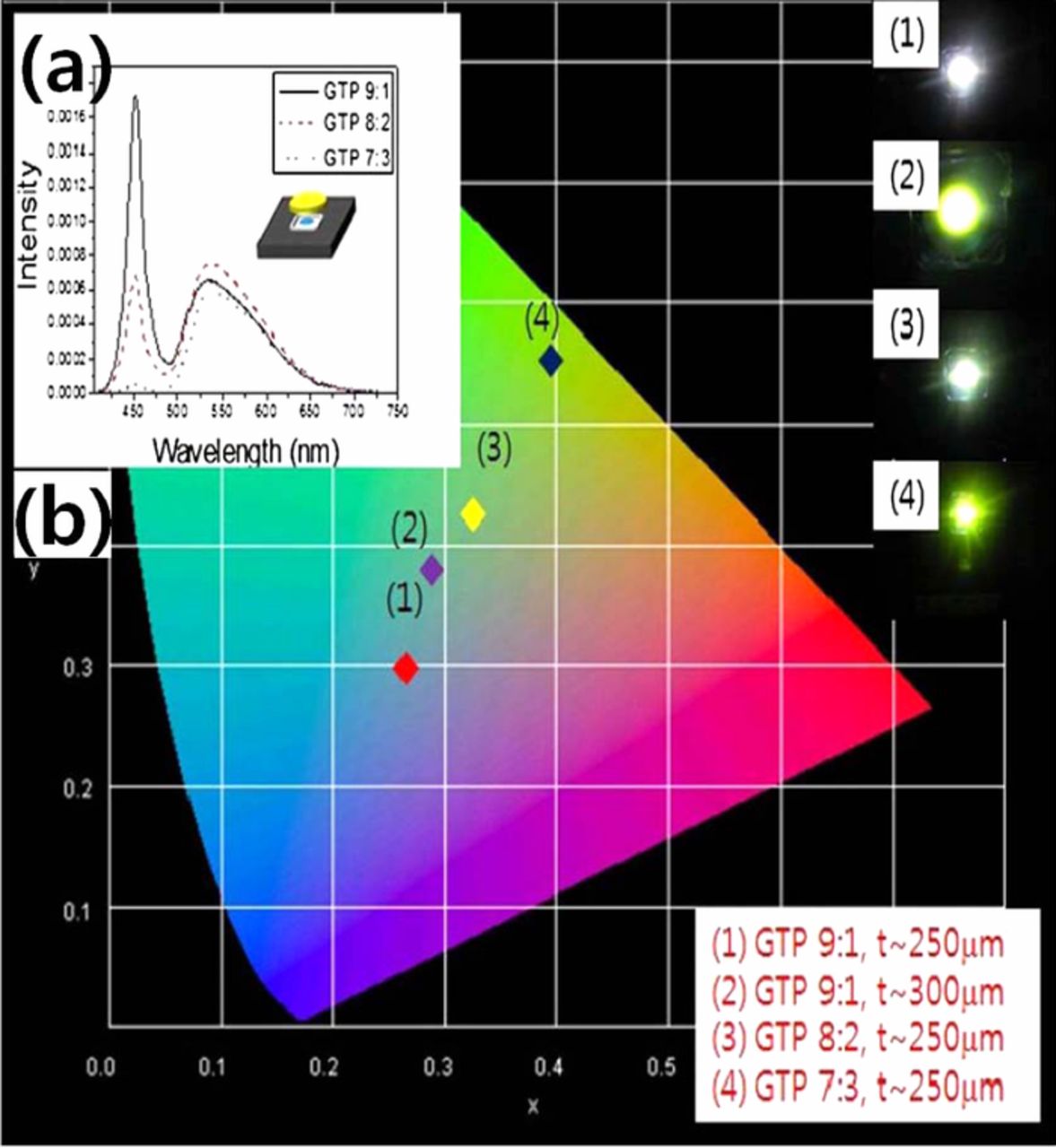
Figure 2. (a) Electroluminescence and photoluminescence (EL+PL) spectra of PiG mounted wLED varying silicate glass to phosphor (GTP) ratio and (b) color coordinates of wLEDs varying GTP ratio and thickness of PiG Plate (Reprinted with permission from Ref. 25. Copyright 2012 Optical Society of America).
Phosphors and Glass Materials for PiG
Enhanced stability of PiG
Encapsulation of phosphor materials with an inorganic glass matrix can provide highly improved thermal and chemical stability, which is the primary purpose of PiG, and promote its commercialization. Compared to phosphor in silicone (PiS), improved thermal quenching property of PiG up to 200°C has been demonstrated and was attributed to thermal conductivity of glass materials (typically 0.5–1.2 W/m⋅K) that was higher than silicone resin (∼0.2 W/m⋅K) (Fig. 3a).25,31–34 Practical reliability of PiG plate has been clearly demonstrated in terms of luminous flux change with aging time under 85°C/85% humidity conditions with a 1 A operation current and a 150°C junction temperature where PiG maintained ∼97% of its luminous flux even after 1,000 hours, while PiS failed before 500 hours35 (Fig. 3b). The reduced luminous efficacy losses and CCT over time have also been reported, which supported the enhanced reliability of PiG over PiS as shown in Figs. 3c and 3d, respecitvely.31–34 Although the improved stability has been mostly proved by oxide phosphors such as YAG:Ce3+, which has high thermal stability, glass can also provide robustness with other phosphors which have relatively low chemical and thermal stability, such as sulfide36,37 and nitride phosphors.38 Lee et al. successfully fabricated a PiG using the SrGa2S4:Eu2+ green phosphor, which easily reacted with the atmospheric moisture and showed improved stability against humidity as well as the thermal stability.36,37 The photoluminescence (PL) and excitation band (PLE) spectra of PiG maintained up to 97% of the initial intensity while the sulfide powder reduced its intensity down to ∼75% when they were immersed in water at 85°C for 48 hours.37 The moisture sensitive SrLiAl3N4:Eu2+ phosphor was also stabilized via introduction of a glass matrix.38 SrLiAl3N4:Eu2+-PiG maintained 90% of its PL intensity while the emission intensity of phosphor powder significantly dropped to 2% when they were immersed in water. The PiG also maintained its intensity up to 96% at 150°C while the phosphor powder showed 90% of its initial intensity proving the improved thermal stability.38 Further enhancement of thermal stability of PiG has been accomplished via effective heat dissipation delivered by the graphene coating on the PiG surfaces.39,40
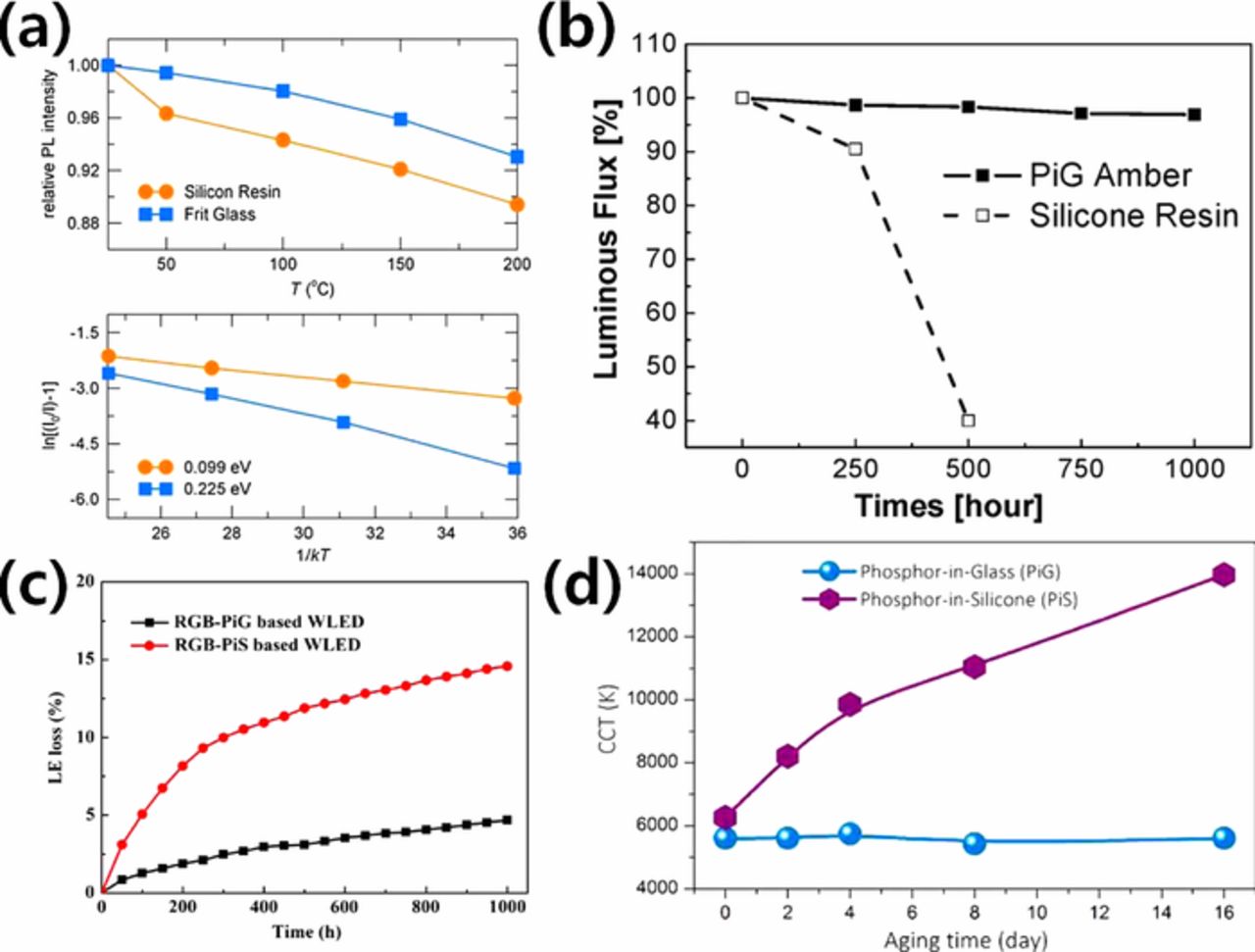
Figure 3. (a) Temperature dependent emission intensity (top) and activation plots for thermal quenching (bottom) of PiG and PiS based wLEDs containing YAG:Ce3+ (Reprinted with permission from Ref. 25. Copyright 2012 Optical Society of America). (b) Luminous flux change of the amber LEDs with PiG and PiS containing Ca-α-SiAlON:Eu2+ at junction temperature of 150°C under 85°C/85% humidity condition with 1 A operation current (Reprinted with permission from Ref. 35. Copyright 2016 Optical Society of America). (c) Luminous efficacy loss of PiG and PiS based wLEDs containing CASN:Eu2+, Ba2Mg2Si2O7;Eu2+ and (Sr,Ba)3MgSi2O8:Eu2+ (Reprinted with permission from Ref. 32. Copyright 2017 Optical Society of America) (d) CCT change of wLEDs with PiG and PiS aged at 200°C (Reprinted with permission from Ref. 33. Copyright 2015 American Chemical Society).
Phosphors for PiG
After successful demonstration of PiG with YAG:Ce3+, various phosphors have been proposed to fabricate PiG. Garnet based oxide phosphors such as Y3Mg2AlSi2O12:Ce3+, Y3Al4.6Ga0.4O12:Ce3+41 and Lu3Al5O12:Ce3+ (LuAG:Ce3+),42–44 which have a high thermal stability similar to YAG:Ce3+, have also been fabricated in PiG plate. Other oxide based phosphors were employed to fabricate PiG: namely, La2Ti2O7:Eu3+,45 BaMgAl10-2xO17:xMn4+, xMg2+,46 Ca2LaSbO6:Eu3+,47 La2LiSbO6:Mn4+, Mg2+,48 CaO:xCe3+,49 Li3Mg2SbO6:Mn4+,50 Li2MgTiO4:Mn4+, Hf4+,51 La0.5Na0.5TiO3:Eu3+,52 BaMgAl10O17:Eu2+,53 3.5MgO-0.5MgF2-GeO2:Mn4+,54 ZnGa2O4:Cr3+55 and SrB4O7:Sm2+.56 Nitride phosphors such as CaAlSiN3:Eu2+ (CASN:Eu2+),57,58 SrLiAl3N4:Eu2+38 and La3Si6N11:Ce59 have also been successfully embedded within a glass matrix to compose PiG. Oxynitride phosphors based on Ca modified Ca1.8Si8.4Al3.6O0.45N15.6:Eu0.04 (Ca-α-SiAlON:Eu2+),35 β-SiAlON:Eu2+60 and Ca14Mg2Si8O28+δN4-δ:Eu2+61 were also incorporated into a glass matrix to fabricate a LED. A single phosphor or two to three different phosphors were mixed with a transparent glass powder depending on the desired color coordinate or color properties of the packaged LED and will be discussed in the following sections.
Among various phosphors, commercial phosphors such as YAG:Ce3+ (yellow), LuAG:Ce3+ (green), CASN:Eu2+ (red), Ca-α-SiAlON:Eu2+ (amber) and β-SiAlON:Eu2+ (green) have been widely used for high power LED applications due to their relatively high thermal stability, because it is crucial to avoid possible thermal degradation of phosphors during the sintering process in order to guarantee the color conversion efficiency of the embedded phosphors. Chen et al.62 observed the interaction between YAG:Ce3+ and a silicate glass matrix with a high resolution transmission electron microscope (HR-TEM) and found that the color converting efficiency was increased as the sintering temperature decreased. Oxidation of Ce3+ and the corrosion of the glass matrix that modified the lattice structure around Ce3+ were responsible for the efficiency decrease at an elevated temperature.63 Although YAG:Ce3+ can be sintered even up to 800°C, CASN:Eu2+ loses its emission intensity significantly when it is heat treated above 550°C.57 The quantum yield drop of the PiG with CASN:Eu2+ above 600°C has also been observed,58 which suggests the importance of thermal stability of the phosphor and sintering temperature.
Glass systems for PiG
Transparent glass is highly important for embedding phosphors and replacing conventional organic silicone resin. In order to provide a robust inorganic matrix for phosphors, the glass needs to meet several requirements: 1) high transparency in the visible range, 2) low sintering temperature to avoid thermal degradation of phosphors, 3) high chemical and thermal stability to guarantee long term stability, 4) RoHS (restrictions of hazardous substances)-free composition and 5) no reaction with the embedded phosphors. For commercial application, glass materials must be readily available and cost competitive against conventional high power silicone resin. The glass powder also needs to have a powder size preferably less than 10 μm to be thoroughly mixed with phosphor powders.
Various glass systems which have been proposed for PiG are summarized in Table I. As found in the table, mostly oxide glasses, such as silicates, borate, phosphate, heavy-metal oxide and tellurite glasses, were extensively used for PiG along with oxyfluoride glasses. As discussed earlier, the sintering temperature of the glass is highly important as it determines the available phosphors and production cost. Since the SiO2-B2O3-RO (R = Ba, Zn) system was introduced for Pb-free glass for YAG:Ce3+ yellow phosphor with a 750°C sintering temperature,25 various glasses were introduced to reduce sintering temperature as well as to embed other phosphors with lower thermal stability than garnet based phosphors such as CASN:Eu2+ (red) which mostly need to be sintered below 600°C. Other than yellow phosphor, the introduction of red and green phosphors which have low stability has been crucial for the control of the LED color properties such as chromaticity, CCT, CRI, and color gamut. SiO2-Na2O-RO (R = Ba, Zn) glass was suggested to embed YAG:Ce3+ and CASN:Eu2+ (red) with the sintering temperature of 550°C and showed that the color coordinate and CCT of LED can be easily controlled by the introduction of CASN:Eu2+.57 Other silicate glasses based on SiO2-B2O3-ZnO-Na2O83 with a sintering temperature of 550°C showed that the CRI can be improved up to 93. The sintering temperature of silicate glass was decreased to 500°C using a SiO2–P2O5–ZnO–B2O3–R2O system and achieved a high CRI of 93.93 A recent study on silicate glass revealed that the sintering temperature of the glass should be also carefully managed to avoid possible crystallization, which is detrimental for the viscous flow and transparency of the glass.69 Although heavy metal oxide glasses based on Bi2O3,63,105–109 PbO96–103 and Sb2O3111,112 can provide sintering temperature lower than 600°C as shown in Table I, they possess either RoHS elements or elements with visible absorption, which can vary color coordination of the LED, and thus it is difficult to use them for commercial application. Tellurite glasses can also reduce the sintering temperature down to 520°C,56,122–134 but they also have visible absorption and the high production cost of TeO2, which hampers mass production. Borate60,113,114 and phosphate115–119 glasses can be sintered below 600°C but they have weak chemical stability against moisture. Low sintering temperature below 400°C has been achieved with oxyfluoride glass based on SnO-SnF2-P2O5135–138 and Bi2O3-B2O3.109 SnO-SnF2-P2O5 glasses were sintered even at 230 and 285°C135,136 but they easily crystallized during the glass preparation and had weak chemical and thermal stability, which restricted their practical feasibility.
Table I. Glass systems for PiG.
| Sintering | |||||
|---|---|---|---|---|---|
| Glasses | Composition | Tg (°C) | Temperature (°C) | Phosphor | Reference |
| Silicate | SiO2-Al2O3-Na2CO3-CaO | 579 | 600∼700 | Lu3Al5O12:Ce3+, CaAlSiN3:Eu2+ | 64,65 |
| SiO2-Al2O3-Na2CO3-CaO:5mol% Eu3+ | 599 | 680 | Sr4Al14O25:Eu2+ | 66 | |
| SiO2-Na2O-ZnO-CaO | 660 | Y3Al5O12:Ce3+ | 67 | ||
| SiO2-Al2O3-Na2O-CaO-TiO2 | 570 | 610∼690 | La3Si6N11:Ce | 59 | |
| SiO2-Na2O-K2O-Al2O3 | 720 | 700∼900 | Y3Al5O12:Ce3+ | 68 | |
| SiO2-Na2O-RO (R = Ba, Zn) | 431, 457 | 550 | Y3Al5O12:Ce3+, CaAlSiN3:Eu2+ | 57,69 | |
| SiO2-Na2O-CaO | 800∼1000 | Y3Al5O12:Ce3+, Lu3Al5O12:Ce3+ | 42 | ||
| SiO2 | 500 | β-SiAlON:Eu, α-SiAlON:Eu, Y3Al5O12:Ce | 70 | ||
| SiO2 | 1050, 600 | β-SiAlON:Eu | 71 | ||
| SiO2-B2O3-RO (R = Ba, Zn) | 590 | 750 | Y3Al5O12:Ce3+, Ca-α-SiAlON:Eu | 25,35 | |
| SiO2-B2O3-BaO-ZnO | 560 | 650∼750 | β-SiAlON:Eu2+ | 72 | |
| SiO2-Al2O3-B2O3-ZnO-BaO | 585 | 700∼800 | Y3Al5O12:Ce3+, 3.5MgO-0.5MgF2-GeO2:Mn4+, (Sr,Ca)AlSiN3:Eu2+, Ca-α-SiAlON:Eu2+ | 34,73 | |
| SiO2-B2O3-Al2O3 | 470 | 550∼600 | Y3Al5O12:Ce3+, CaAlSiN3:Eu2+, Ba2MgSi2O7:Eu2+, (Sr,Ba)3MgSi2O8:Eu2+ | 74–76 | |
| SiO2-B2O3-Al2O3-ZnO | 450 | 500∼600 | Lu3Al5O12:Ce3+, (Sr,Ca)AlSiN3:Eu2+ | 77 | |
| SiO2-B2O3-ZnO-BaO-Na2O | 600∼800 | CaAlSiN3:Eu2+ | 58 | ||
| SiO2-B2O3-ZnO-Al2O3-K2O | 600 | Lu3Al5O12:Ce3+, CaAlSiN3:Eu2+ | 78 | ||
| SiO2-B2O3-ZnO-R2O | 630 | Y3Al5O12:Ce3+ | 79 | ||
| SiO2-B2O3-ZnO-Li2O | 510 | 630 | Lu3Al5O12:Ce3+, Y3Al5O12:Ce3+, (Sr,Ba)Si2O2N2:Eu2+, CaAlSiN3:Eu2+ | 80 | |
| SiO2-B2O3-ZnO-Na2O | 425 | 550∼620 | Y3Al5O12:Ce3+, Lu3Al5O12:Ce3+, Sr2SiO4:Eu2+, CaAlSiN3:Eu2+, (Sr,Ba)Si2O2N2:Eu2+ | 81–83 | |
| SiO2-B2O3-ZnO-K2O | 436∼450 | 580∼630 | Y3Al5O12:Ce3+ | 84,85 | |
| SiO2-B2O3-RO-R2O-Al2O3 (R = Zn, Ba, Na, K, Li) | < 550 | 540∼660 | Y3Al5O12:Ce3+ | 86 | |
| SiO2-B2O3-ZnO-Li2O-La2O3-WO3 | 410∼538 | 575∼700 | Y3Al5O12:Ce3+, CaAlSiN3:Eu2+ | 87–91 | |
| SiO2-B2O3-ZnO-Li2O-Na2O-La2O3-WO3 | 509∼541 | 640∼700 | Y3Al5O12:Ce3+ | 92 | |
| SiO2-P2O5-ZnO-B2O3-R2O (R = K, Na) | 410 | 500∼550 | Y3Al5O12:Ce3+, CaAlSiN3:Eu2+ | 93–95 | |
| Heavy metal oxide | PbO-B2O3-SiO2-Eu2O3 | 550 | CaAlSiN3:Eu2+, Y3Al5O12:Ce3+ β-SiAlON:Eu2+, Sr5(PO4)3Cl:Eu2+ | 96,97 | |
| PbO-B2O3-SiO2 | 600∼650 | Y3Al5O12:Ce3+, ZrO2 powder | 98,99 | ||
| PbO-B2O3-SiO2-ZnO | 580∼750 | Y3Al5O12:Ce3+ | 100–102 | ||
| SiO2-PbO-PbF2-AlF3 | 550 | Y3Al5O12:Ce3+, SiAlON:Eu2+ | 103 | ||
| Sb2O3-PbO-B2O3 | 750∼1100 | Y3Al5O12:Mn4+ | 104 | ||
| Bi2O3-H3BO3-ZnO | 500 | 550∼800 | Y3Al5O12:Ce3+, LuAG:Ce3+,CaAlSiN3:Eu2+ | 63,105 | |
| B2O3-Bi2O3-Al2O3-ZnO | 550 | Y3Al5O12:Ce3+, CaAlSiN3:Eu2+ | 106 | ||
| Bi2O3-B2O3-ZnO-Al2O3-BaO | 600 | LuAG:Ce3+, CaAlSiN3:Eu2+ | 107 | ||
| Bi2O3-ZnO-B2O3-CeO2 | 460 | 500∼560 | Y3Al5O12:Ce3+ | 108 | |
| Bi2O3-B2O3-ZnO-Sb2O5 | 307 | 325∼390 | Y3Al5O12:Ce3+ | 109 | |
| B2O3-Bi2O3-CaO | 396∼466 | 650∼800 | Y3Al5O12:Ce3+ | 110 | |
| Sb2O3-B2O3-ZnO-K2O | 309 | 600∼750 | Y3Al5O12:Ce3+ | 111,112 | |
| Borate | ZnO-B2O3-BaO-Al2O3 | 547 | 620∼680 | β-SiAlON:Eu2+, CaAlSiN3:Eu2+ | 60,113 |
| ZnO-B2O3 | 547∼573 | 1000 | Ca-α-SiAlON:Eu2+ | 114 | |
| Phosphate | P2O5-B2O3-ZnO-Na2O-K2O-Li2O-Al2O3 | 396∼447 | 550∼700 | Y3Al5O12:Ce3+, CaAlSiN3:Eu2+ | 115,116 |
| P2O5-Al2O3-Na2O-K2O-B2O3-SiO2-CaO-BaO-ZnO | 372 | 550 | BaSi2O5:Eu2+, Nd3+ | 117 | |
| P2O5-ZnO-B2O3-BaO-R2O-Al2O3 (R = Na, K, Li) | 390∼445 | 600 | Y3Al5O12:Ce3+ | 118 | |
| P2O5-ZnO-Na2O-Li2O-BaO | 540 | Y3Al5O12:Ce3+, Sr2Si5N8:Eu2+ | 119 | ||
| P2O5-ZnO-Bi2O3 | 426∼460 | 700 | Y3Al5O12:Ce3+ | 120 | |
| P2O5-ZnO-BaO-Na2O | 850∼1000 | Y3Al5O12:Ce3+ | 121 | ||
| Tellurite | TeO2-ZnO | 600 | SrB4O7:Sm2+ | 56 | |
| TeO2-ZnO-Na2O | 450∼700 | Y3Al5O12:Ce3+ | 122 | ||
| TeO2-Na2O-ZnO-B2O3 | 450∼600 | Y3Al5O12:Ce3+, 3.5MgO-0.5MgF2-GeO2:Mn4+ | 123,124 | ||
| TeO2-ZnO-Na2O-Al2O3 | 525∼625 | 3.5MgO-0.5MgF2-GeO2:Mn4+, Ba2MgSi2O7:Eu2+, (Sr,Ba)3MgSi2O8:Eu2+ | 125 | ||
| TeO2-B2O3-ZnO-Na2O-Al2O3 | 520∼600 | Y3Al5O12:Ce3+, Mn2+, Si4+ | 126,127 | ||
| TeO2-B2O3-Sb2O3-ZnO-Na2O-La2O3-BaO | 540–690 | Gd3Al2Ga3O12:Ce3+, Y3Al5O12:Ce3+ | 128,129 | ||
| TeO2-ZnO-Sb2O3-Al2O3-B2O3-Na2O | 600 | Y3Al5O12:Ce3+, SrMgAl10O17:Mn4+, Li+ | 130 | ||
| TeO2-B2O3-Sb2O3-ZnO-Na2O | 600 | Y3Al5O12:Ce3+ | 131 | ||
| TeO2-Li2O-ZnO | 520 | Y3Al4.5Ga0.5O12:Ce3+ | 132 | ||
| TeO2-Sb2O3-Al2O3-B2O3-Na2O-ZnO | 530 | LuAG:Ce3+ | 133 | ||
| TeO2-Sb2O3-Li2O-ZnO | 530 | LuAG:Ce3+ | 134 | ||
| Oxyfluoride | SnO-SnF2-P2O5 | 100∼175 | 230∼370 | Y3Al5O12:Ce3+, (BaSr)2SiO4:Eu2+, (SrCa)AlSiN3:Eu2+, CaAlSiN3:Eu2+ | 135–137 |
| SnO-SnF2-P2O5-MF (M = Li, Na, K, Cs) | 118∼137 | 350∼420 | Y3Al5O12:Ce3+, CaAlSiN3:Eu2+ | 138 |
Thus, for the moment, it seems that the silicate glass systems are promising for commercial application of PiG considering the production cost and long-term stability. However, it is very important to find an appropriate glass material that has a sintering temperature lower than 400°C as well as high chemical and thermal stability, in order to provide the enhanced stability in the newly developed phosphors with low thermal stability such as K2SiF6:Mn4+ (KSF).139
Fabrication Methods of PiG
The fabrication of PiG has been introduced by the direct pouring of molten glass onto a phosphor24 or remelting the glass with phosphor powders above 1000°C.140 However, high temperature of the molten glass deteriorates the embedded phosphor resulting in loss of conversion efficiency. Thus, as illustrated in Fig. 1, PiG is normally fabricated by sintering a glass-phosphor mixture using the viscous flow of the glass under the temperature at which thermal degradation of the phosphor can be avoided. The transparent glass powder and phosphor needs to be thoroughly mixed and packed into a green body with a disk shape under uniaxial pressure. After sintering at the elevated temperature, the obtained PiG plate needs to be optically polished adjusting the thickness to be mounted on top of the blue LED chip.
Although the viscous flow of the glass can give good contact to the phosphors, pores can be trapped within the PiG plate after sintering. Incomplete densification of the powders during the green body forming process, trapped gases during the sintering process and high viscosity of the glass at the sintering temperature are mostly responsible for the pores within the PiG plate. The pores act as a scattering center within the plate and decrease the transparency of the plate. Kim et al.84,91,92 investigated the effect of pores on the transparency of PiG and luminous efficacy and suggested that the transparency depends on the porosity and it needs to be properly optimized for the CCT and luminous efficacy via scattering management. Yoon et al. introduced gas pressured sintering (GPS) after green body formation and completely removed the pores, thus ensuring the color conversion efficiency of the Ca-α-SiAlON.35
While sintering of PiG plate is most promising and currently used for commercial mass production, it requires an additional adjustment of thickness and thus brings inevitable material loss during the polishing process. For example, when the sintered PiG plate with 1.5 mm thickness needs to be polished into a 150 μm thickness, it loses around 90 volume percent of the material used. Moreover, it is hard to produce various shapes as the powders need to be packed with a mold with a limited shape. Various fabrication methods have thus been studied to overcome the shortcomings of the conventional sintering process.
Chae et al.141 and Yang et al.142 demonstrated that PiG can also be fabricated in a thick film on a glass substrate using a screen printing process. Thick film does not need an additional polishing process and it is relatively easy to fabricate various shapes by simply changing the screen design. As shown in Fig. 4a,142 the glass and phosphor powders are mixed thoroughly with an organic vehicle to make a paste and screen printed on a substrate followed by the sintering process at an elevated temperature. Peng et al.86 reported that the luminous efficacy decreased while the CCT increased as the film thickness and phosphor content increased. They also showed improved stability in the PiG thick film compared to PiS using a YAG:Ce3+ phosphor. Ahn et al.94 fabricated a PiG thick film with YAG:Ce3+ and CASN:Eu2+ phosphors using silicate glass with a low sintering temperature and successfully demonstrated that the chromaticity and CCT of the PiG thick film could also be adjusted by the introduction of a red phosphor (CASN:Eu2+). PiG thick film has also been formed on a sapphire substrate to dissipate the generated heat efficiently from high power light sources such as laser diodes.87,143
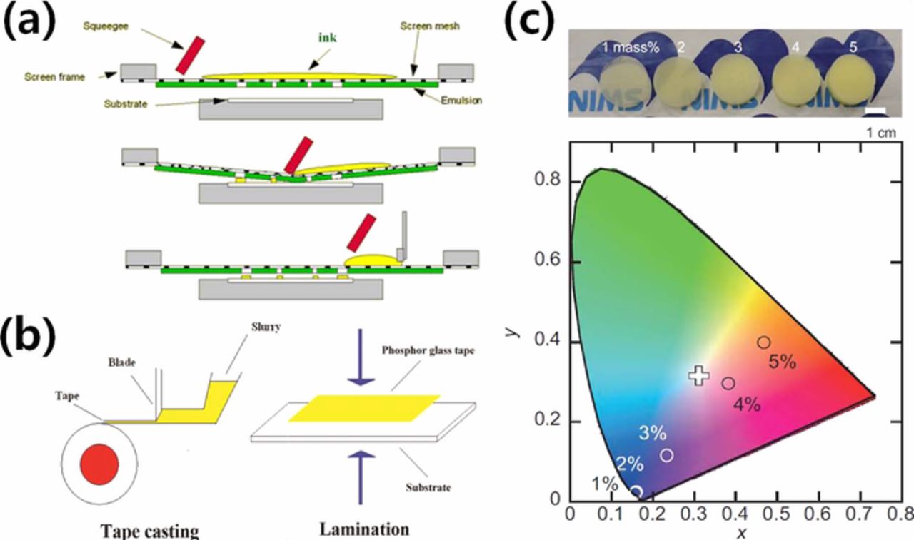
Figure 4. Various fabrication methods of PiG. (a) Screen printing process (Reprinted with permission from Ref. 142. Copyright 2013 Optical Society of America). (b) Tape casting and lamination process (Reprinted with permission from Ref. 100. Copyright 2014 Optical Society of America). (c) Sol-gel process (Adapted from Ref. 144, Copyright 2016 The American Ceramic Society and Wiley Perodicals, Inc).
For the low cost production of PiG plate, tape casting has been introduced as depicted in Fig. 4b.100 The slurry composed of PbO-B2O3-SiO2-ZnO glass powder, YAG:Ce3+, a dispersant, a binder and a plastic agent in ethanol and xylene was prepared and tape casted with 600 μm thickness using a blade. The obtained PiG tape was laminated on a transparent glass substrate and sintered at an elevated temperature.
Facile synthesis of PiG can also be carried out via a sol-gel process. Yoshimura et al.70 prepared a silica precursor sol which was mixed with β-SiAlON:Eu2+ and fabricated the PiG film by dipping a glass substrate into the sol or dropping the sol on the substrate followed by sintering at 500°C. PiG plates with β-SiAlON:Eu2+71 or Ca-α-SiAlON:Eu2+144 have also been synthesized by sol-gel process using silica glass which has been dried and sintered at 600–1050°C. Fig. 4c shows the dried silica gels varying the phosphor content and their corresponding chromaticity diagram.144 Careful design of phosphor system having chemical inertness is required to avoid possible microstructural damage due to high pH during the colloidal process.
Spark plasma sintering (SPS) has also been employed to incorporate phosphor powders within a glass matrix replacing the conventional sintering process with an electric furnace. A PiG plate with YAG:Ce3+ and silica glass has been successfully synthesized via SPS using mesoporous silica SBA-15 powders.145 SPS also enabled the structured phosphor layer formation with glass matrix on the aluminum.74 Sintering of a PiG plate without an electric furnace has also been recently demonstrated by CO2 laser, which significantly reduced the sintering time with a marginal decrease in luminous efficacy.146
Color Conversion Property Improvement of PiG
Chromaticity, CRI and CCT
Although a wLED can be realized only with YAG:Ce3+ yellow phosphor, its chromaticity, CRI and CCT are confined by the values which YAG:Ce3+ allow. As shown in Fig. 2 and Fig. 5a,57 the color coordinate of a PiG-mounted wLED with only YAG:Ce3+ is located on the linear line depending on the amount of yellow phosphor or PiG thickness. However, the increased demand on the wLED with a high CRI or a low CCT (warm-white) requires manipulation and tunability of chromaticity to compensate for the limited green or red emission intensity of YAG:Ce3+. A high CRI is crucial for lighting applications to obtain an object's natural colors under a wLED similar to daylight conditions under the sun. A warm wLED with a low CCT is also important for indoor applications considering the circadian rhythm.147 As discussed earlier, incorporation of a commercial red phosphor such as CASN:Eu2+ along with YAG:Ce3+ was enabled by a glass with a low sintering temperature and it demonstrated chromaticity tunable wLEDs following the Planckian locus as shown in Fig. 557 as well as a high CRI up to 93 and a low CCT below 4,100 K.83,93,94 YAG:Mn4+ modified with various dopants such as Gd, Lu, Ga, Li, Na, Mg, Ca and Ge has been also mixed with YAG:Ce3+ as a red phosphor to make a color tunable white LED with the improved CRI using tellurite glass matrix.148–150 As the color conversion spectra of the PiG depend on the embedded phosphors, the proper combination of phosphors can easily tune the chromaticity. For example, chromaticity tuning of the wLED has also been carried out by mixing green (LuAG:Ce3+) and red (CASN:Eu2+) phosphors.64,77,107 Other combinations of phosphors are also possible for color tunable wLEDs: Y3Mg2AlSi2O12:Ce3+ (orange)+Y3Al4.6Ga0.4O12:Ce3+ (green),41 BaMgAl10O17:Mn4+, Mg2+ (red)+YAG:Ce3+ (yellow),46 La0.5Na0.5TiO3:Eu3+ (red)+YAG:Ce3+ (yellow)52 and so on. Color tunable wLED under UV-LED incorporating three phosphors – CASN:Eu2+ (red), Ba2MgSi2O7:Eu2+ (green) and (Sr,Ba)3MgSi2O8:Eu2+ has been also reported.32 More combinations of phosphors can be found in a previous review29 and Table I.
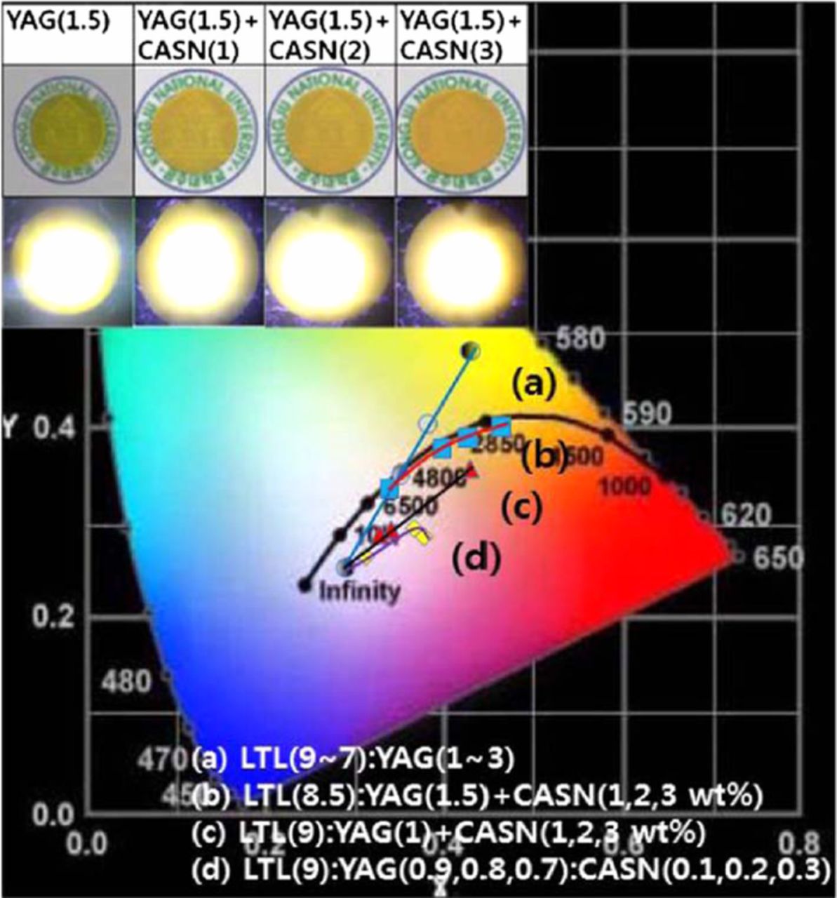
Figure 5. CIE color coordinates of PiGs (a) varying glass (LTL) to phosphor (YAG:Ce3+) ratio, (b) varying additional CASN:Eu3+ content with the fixed glass to phosphor ratio of 8.5:1.5, (c) varying additional CASN:Eu3+ content with the fixed glass to phosphor ratio of 9:1 and (d) varying CASN:Eu3+ content replacing YAG:Ce3+ with the fixed glass to phosphor ratio of 9:1 (Reprinted with permission from Ref. 57. Copyright 2014 Optical Society of America).
Compensation of colors for the phosphors can be also supplied by the doped rare earth ions such as Eu3+ within the host glass matrix.96,151 Additional glass with Eu3+ has also been applied on top of the PiG plate with YAG:Ce3+ to tune the resultant CCT.152 However, due to the limited absorption cross section of rare earth ions within a glass matrix, their color tunability has been restricted compared to that of the PiG with multiple phosphors.
Luminous efficacy
The luminous efficacy (LE) of the wLED represents the ratio of the measured luminous flux (lm) of the LED to the given power (W): It is highly important for reducing power consumption. The LE of wLEDs mounted with various PiGs, which was summarized in a previous review,29 mostly depends on the color conversion efficiency of the PiG plate, which is determined by the content and quantum yield of the embedded phosphors, the transparency of the glass matrix and the light extraction efficiency. The quantum yield of phosphors normally does not vary significantly but can deteriorate when they are thermally degraded during the sintering process due to the reaction with the glass matrix or phosphor surface oxidation as discussed earlier. Under the same conditions as for phosphors, the LE of PiG thus relies on the transparency of the glass matrix and the light extraction efficiency of the PiG plate. As introduced earlier, Kim et al.91 investigated the effect of transmittance on the luminescence properties of PiG and observed that the transmittance decreased with the trapped pores within the glass because scattering reduced the resultant LE. They also found that the proper management of pore size and porosity also improves the LE due to the optimized scattering paths as illustrated in Fig. 6.92 The inherent transparency of the glass can be obtained without pores via additional pressure during the sintering process, such as using GPS to improve the LE.35 External impurities during the grinding and screening process of the glass powders is also a major source for light absorption and should be carefully removed to avoid additional loss of transparency and LE.
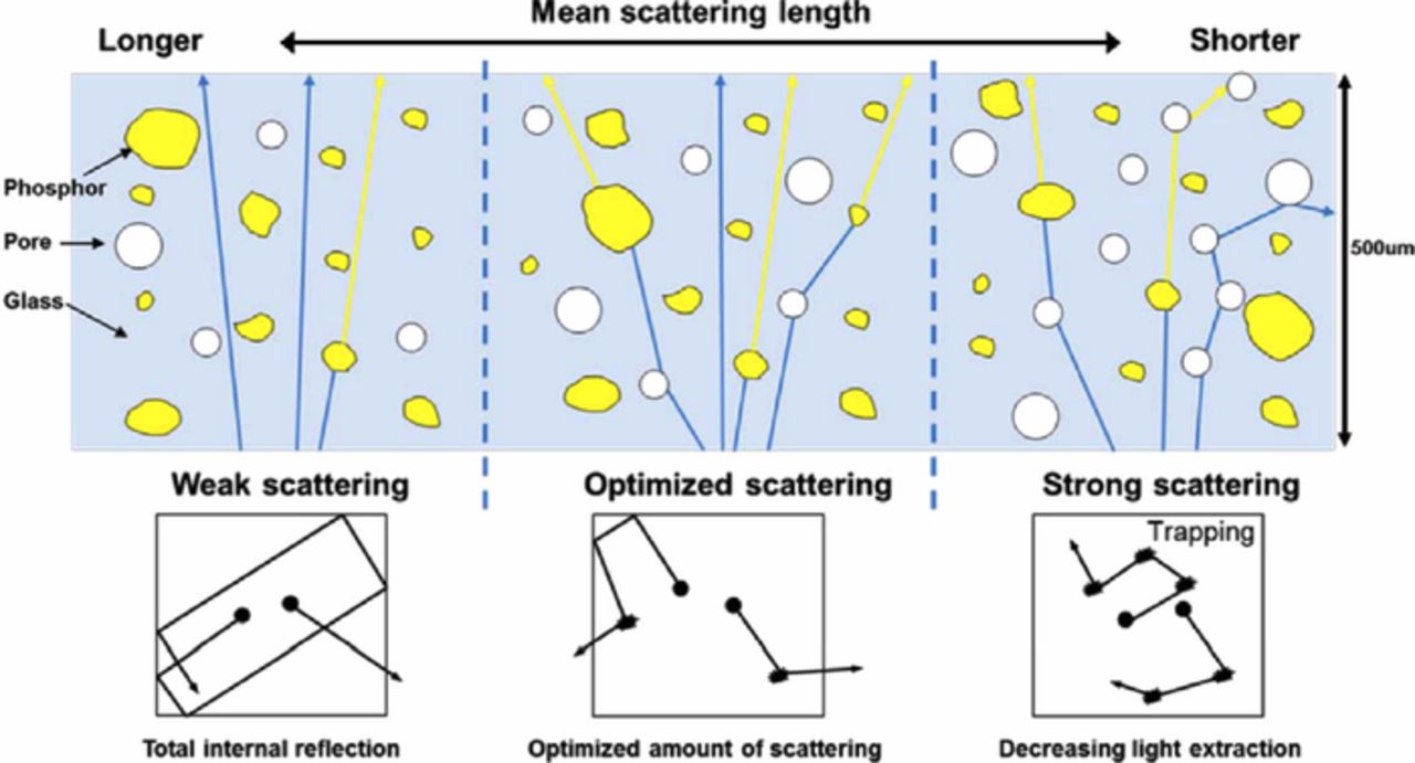
Figure 6. Schematic diagram illustrating the interaction of blue light with phosphor and pores within a PiG plate depending on the scattering type (Reprinted with permission from Ref. 92. Copyright 2015 Optical Society of America).
Scattering of the excitation (blue) light and the converted light can also occur at the phosphor/glass interface due to the different refractive indexes (RIs) of the phosphor and glass matrix. For example, the RI of YAG:Ce3+ is 1.83 while that of the silicate glass (SiO2-B2O3-RO) is ∼1.57,25 which causes the scattering of the blue light as well as the converted yellow light, which reduces the excitation and light extraction efficiency of the phosphors. Thus, employing a glass matrix with a high RI similar to phosphor can increase the light extraction efficiency as well as the LE of PiG. Seo et al.90 confirmed the increase of light extraction efficiency and LE of PiG with an increase in the glass RI when PiG was mixed with YAG:Ce3+. Zhang et al.129 employed a high RI glass based on Sb2O3-B2O3-TeO2-ZnO-Na2O-La2O3-BaO for YAG:Ce3+ and obtained a high LE of 124.6 lm/W under a high operating current of 350 mA LED for the first time as depicted in Fig. 7. A similar high quantum yield (93%) and high LE up to 137 lm/W was also observed with TeO2-ZnO-Sb2O3-Al2O3-B2O3-Na2O-Eu2O3 glass.153 Chen et al.154 used Sb2O3 based glass (Sb2O3-ZnO-K2O-B2O3) for YAG:Ce3+ and obtained a high quantum yield of 94% as well as a high LE of 130 lm/W under a 350 mA operating current.
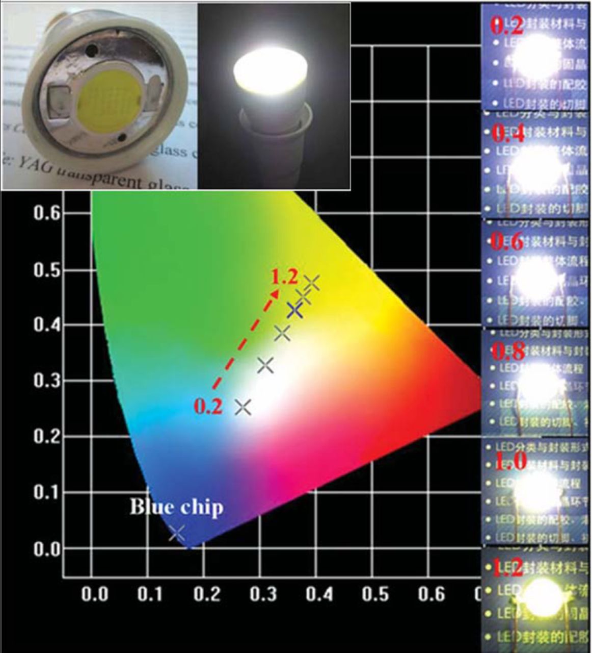
Figure 7. wLED packaged with Sb2O3-B2O3-TeO2-ZnO-Na2O-La2O3 glass based PiG and its CIE color coordinates varying PiG thickness in mm under 350 mA LED operation current (Reprinted with permission from Ref. 129. Copyright 2013 WILEY-VCH Verlag GmbH & Co. KGaA, Weinheim).
The effect of the refractive index of the glass matrix on the light extraction efficiency has also been observed from a screen printed PiG thick film.88 For the thick film type PiG, as exhibited in Fig. 8, a multi-layered PiG thick film with glasses with different RIs was proposed to obtain a graded refractive index film and to increase the light extraction efficiency.89,118 The light extraction efficiency of the PiG thick film can be further improved reducing the total internal reflection at the interface between the glass and air. Wang et al.155 and Xu et al.82 created a textured structure on the surface of a substrate glass via chemical wet etching and confirmed an increase in luminous efficacy.
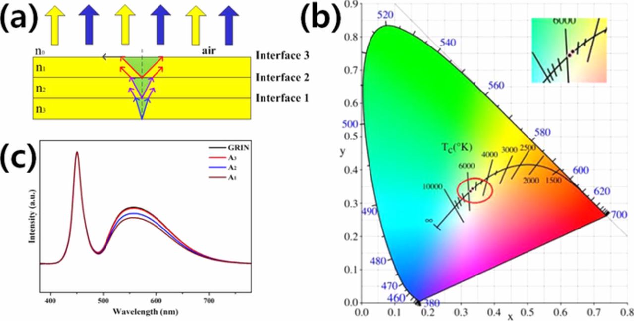
Figure 8. (a) Gradient refractive index (GRIN) structure (n3>n2>n1>n0) of PiG layers and (b) CIE color coordinate and (c) normalized EL spectra of wLEDs based on PiG coatings with GRIN structured, A1, A2 and A3 glasses. A1, A2 and A3 glasses have refractive index of n1, n2 and n3, respectively. (Reprinted with permission from Ref. 89. Copyright 2018 The American Ceramic Society).
The LE of a wLED can also be improved by avoiding the re-absorption of the converted light by the neighboring phosphors. When a green or yellow phosphor is mixed with a red phosphor, the emission can be absorbed by a nearby red phosphor due to a spectral overlap that reduces the emission intensity and color purity. Thus, separation of the phosphor layers has been suggested. Peng et al.75 prepared a multi-layered PiG that has different phosphors with varying stacking order such as red (R)-green (G)-blue (B) and G-R-B to fabricate a wLED under UV-excitation as depicted in Fig. 9a. The LE of the multi-layered PiG was improved over that of the PiG with mixed-RGB phosphors due to the reduced re-absorption. Lee et al.156 and Kim et al.78 proposed a segmented PiG plate which is assembled by separately prepared green and red PiGs as shown in Fig. 9b. The segmented PiG showed improved green emission with a marginal increase in LE, which suggested reduced reabsorption compared to the PiG with mixed R-G phosphors. Similar segmented PiGs with various patterns have also been fabricated via screen printing as displayed in Fig. 9c, and they had improved luminous properties.29,157 Additional introduction of a crater-type resin on top of the patterned PiG further improved the LE as well as the uniformity of the CCT, which will be discussed in the following section (Fig. 9d).158 Micro-structure array (MSA) on top of the patterned PiG has also been employed to enhance the LE as well as the angular color distribution via broadening the light escaping area (Fig. 9e).159
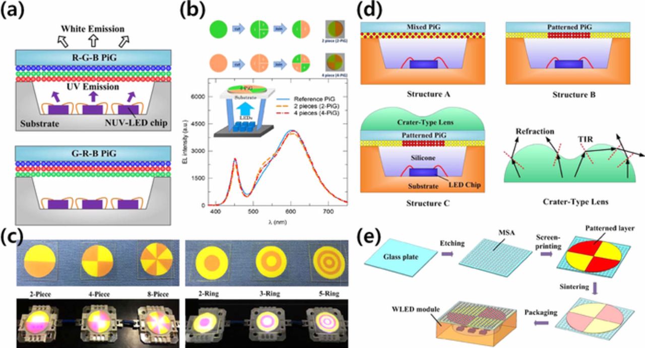
Figure 9. (a) Schematic diagram of multilayered PiG with RGB and GRB layers under UV-LED (Reprinted with permission from Ref. 75. Copyright 2016 Optical Society of America). (b) Illustration of the fabrication of segmented PiG with 2-pieces and 4-pieces and EL+PL spectra of wLED with 4-piece segmented PiG (Reprinted with permission from Ref. 156. Copyright 2014 Optical Society of America). (c) PiGs with various pattern structures and the LED modules mounted with them (Reprinted with permission from Ref. 29. Copyright 2018 WILEY-VCH Verlag GmbH & Co. KGaA, Weinheim). (d) Schematic diagram of patterned PiG with crater type lens (Reprinted with permission from Ref. 158. Copyright 2016 Optical Society of America). (e) Schematic illustration of the wLED moduel packaged by patterned PiG with micro-structure array (MSA) (Reprinted with permission from Ref. 159. Copyright 2017 Optical Society of America).
Angle dependency
When blue LED light passes through a color converting material, the optical path lengths of the rays are different depending on the outgoing angles of the rays from the blue LED chip. Thus, when YAG:Ce3+ is used for a wLED, the light that comes out of the edge of the color converting material experience long interaction length with the phosphor and shifts the chromaticity to yellow with a low CCT value while the center shows the white causing a 'yellow-ring effect'.160,161 To provide high color and CCT uniformity of a wLED, Yi et al.98 introduced ZrO2 powders within the glass matrix to act as a light diffuser and mounted the ZrO2 embedded glass plate on top of the PiG plate with YAG:Ce3+ as exhibited in Fig. 10a, and thus demonstrated improved angle dependency of the CCT. The angle dependency was also reduced with multi-layered PiG thick films forming a cone shape to compensate for the path length as displayed in Fig. 10b.99 A substrate glass with a textured surface that induces scattering also improved the angular color distribution.155 The patterned structure for PiG plates or screen printed PiGs as shown in Fig. 9 has also been reported to improve color uniformity78,157–159 via spatial distribution of colored PiG and adjustment of light path lengths or scattering at the surface. The additional layers for color uniformity can reduce the output intensity which needs to be compromised to achieve high quality white light.
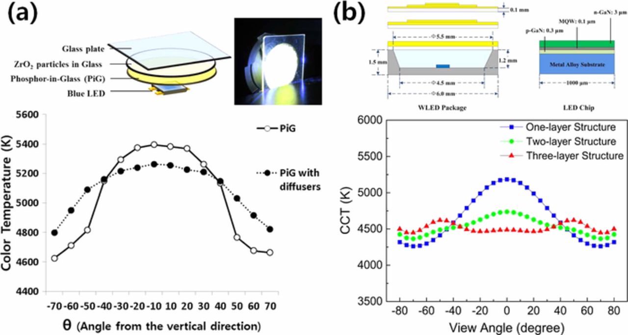
Figure 10. (a) Configuration of PiG with a diffuser layer containing ZrO2 and its effect on the angle dependency of wLED (Adapted from Ref. 98. Copyright 2015 Springer-Open Access). (b) Schematic diagram of wLED with multiple PiG layers and its effect on the angle dependency (Reprinted with permission from Ref. 99. Copyright 2014 Optical Society of America).
Color gamut
The current liquid crystal display (LCD) adapts the wLED as a white light source in the back light unit (BLU), and its color reproduction range relies on the primary R-G-B colors which are realized by the color filters of the LCD. Thus, the spectrum match of the wLED with color filters determines the R, G, B colors, but the broad emission bandwidth of the conventional wLED, which uses green and red phosphors embedded in silicone resin (RG-LED), restricts the color reproduction range (color gamut) at ∼75% to that of the range defined by the national television standard committee (NTSC).162 Han et al. thus employed a Nd3+-doped glass on top of the conventional RG-LED to modify the emission bandwidth via a strong 4f-4f transition of Nd3+:4I9/2→ 4G5/2,2G7/2 and successfully expanded the color gamut up to ∼ 82% of the NTSC standard.162 As the previous work used silicone resin with inherent weak long-term stability, Lee et al. doped the silicate glass with the Nd3+-ion and fabricated a PiG with LuAG:Ce3+ (green) and CASN:Eu2+ (red) phosphors.163 As shown in Fig. 11, the emission spectrum of the wLED with PiG and R and G phosphors (RG-PiG) has also been successfully modified, and its color gamut has been improved from 66 to 80% of the NTSC standard with an increasing Nd2O3 concentration. Similarly, Zhang et al. formed NdF3 nano-crystals within a silicate glass which was mounted on top of the RG-PiG as a color filter and demonstrated an improved color gamut up to ∼79% of the NTSC standard.164 The glass with NdF3 nanocrystals was also used as a host matrix for R-G phosphors but it experienced a limited increase in the color gamut up to 75% of the NTSC standard.165
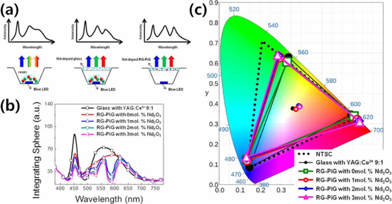
Figure 11. (a) Schematic diagram of wLEDs with their corresponding expected spectra varying color converting materials (PiS with RG phosphors-left, PiS with Nd-doped glass as a filter-center and RG-PiG with Nd-doped glass matrix-right) and (b) visible emission spectra and (c) color reproduction range of wLEDs with RG-PiG varying Nd2O3 content (Reprinted with permission from Ref. 163. Copyright 2018 Optical Society of America).
Applications of PiG
High power LED and LDs for automotive and lighting applications
Due to the enhanced long-term stability of PiG under high temperature and humidity conditions and low manufacturing cost, it has been used in high brightness and high power LED applications to replace conventional PiS in applications such as automotive headlamps. While Philips Lumileds released LUXEON, adapting YAG:Ce3+ CPP as an inorganic color converter in 2008 and applied it to automotive headlamps, PiG was commercially applied to automotive headlamps by Samsung Electronics for the first time in 2013 employing silicate glass and later by other LED manufacturers. As discussed earlier, reasonable stability and LE of a wLED mounted with PiG at a high operation current have been reported by many researchers.29,129,153,154 Similar to LUXEON, PiG with YAG:Ce3+ has been packaged with a flip-chip LED and demonstrated its feasibility for automotive headlamps.166 Lin et al.128 demonstrated a high powered wLED based on an AC-LED that minimized its flickering effect with the afterglow of a PiG plate as illustrated in Fig. 12a. Along with the white headlamp, a monochromatic amber LED has also been proposed as a turning signal light using PiG with Ca-α-SiAlON:Eu2+35 or mixed phosphors with YAG:Ce3+ and CASN:Eu2+.95 The high power wLED can be also used for a lighting lamp, which was demonstrated by Zhang et al. as shown in Fig. 12b.34
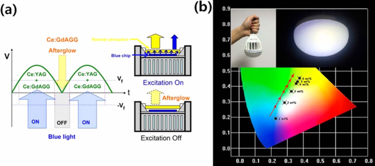
Figure 12. (a) Schematic diagram of wLED for AC-LED applied with persistent GdAGG:Ce3+ PiG (Reprinted with permission from Ref. 128. Copyright 2014 American Chemical Society). (b) Light bulb and lamp packaged with PiG-based wLEDs which can be operated under 300 mA (Reprinted with permission from Ref. 34. Copyright 2017 American Chemical Society).
Recently, a blue laser diode (LD) was considered for the light source of an advanced automotive headlamp with its higher optical power and linearity of light to extend the visible distance. Application of PiG for a LD to produce white light has been reported by several groups.34,68,73,79,87,110,143 Zheng et al.73 produced a high luminance of white lighting using PiG and a blue LD. They introduced PiG thick film with YAG:Ce3+, YAG:Ce3++α-SiAlON or YAG:Ce3++SCASN to show color tunability and a high luminous flux up to 1,839 lm with a high LE of 210 lm/W under 11.2 W/mm LD excitation (Fig. 13a). Recently, Chang et al.167 successfully composed a laser headlight module (LHM) with five blue LDs with a total output power of 6 W and PiG with YAG:Ce3+ as depicted in Fig. 13b and achieved 1,860 lm with a CCT of 4100 K and a high LE of 310 lm/W, which indicates a high performance LHM. Green phosphors such as β-SiAlON,60,72 LuAG:Ce3+44 and La3Si6N11:Ce59 have also been mixed with glass to prepare a PiG for a thermally robust color converter under a high power blue LD.
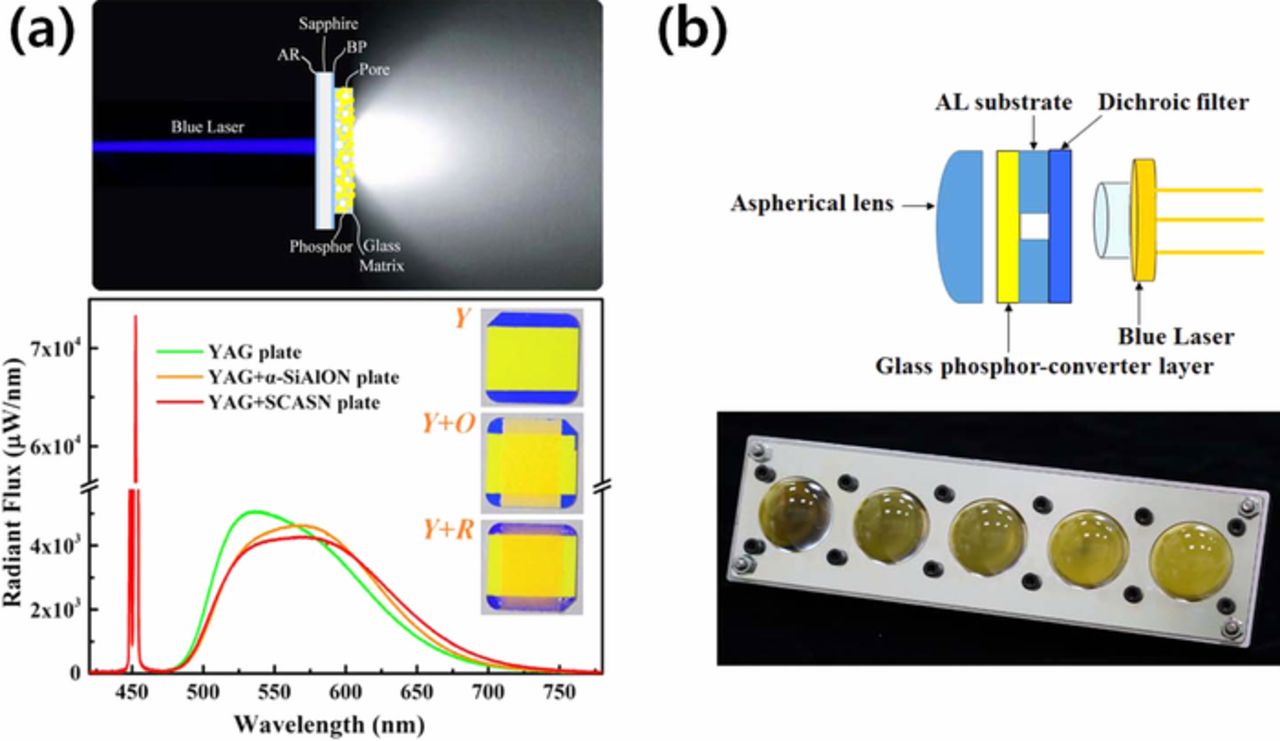
Figure 13. (a) Schematic diagram of LD driven white lights using transmissive configuration of PiG thick films and its radiant flux depending on the applied phosphor layers (Reprinted with permission from Ref. 73. Copyright 2018 American Chemical Society). (b) Schematic diagram of laser headlight module (LHM) and its actual photo with 5 × 1 blue laser array (Adapted from Ref. 167. Copyright 2019 Optical Society of America).
Heat dissipation is highly important, especially for high power applications of LED and LDs. As introduced earlier, materials with high thermal conductivity have been attached to the PiG to effectively dissipate the generated heat at a high operation current such as graphene coating layers on the PiG plate39,40 (Fig. 14a) and a sapphire substrate for PiG thick films.87,143 Park et al.74 fabricated a phosphor (YAG:Ce3+)-aluminum composite via PiG layer formation on the aluminum surface and effectively reduced the maximum surface temperature from 258 to 137°C obtaining 430 lm at 4 W blue LD output power (Fig. 14b).
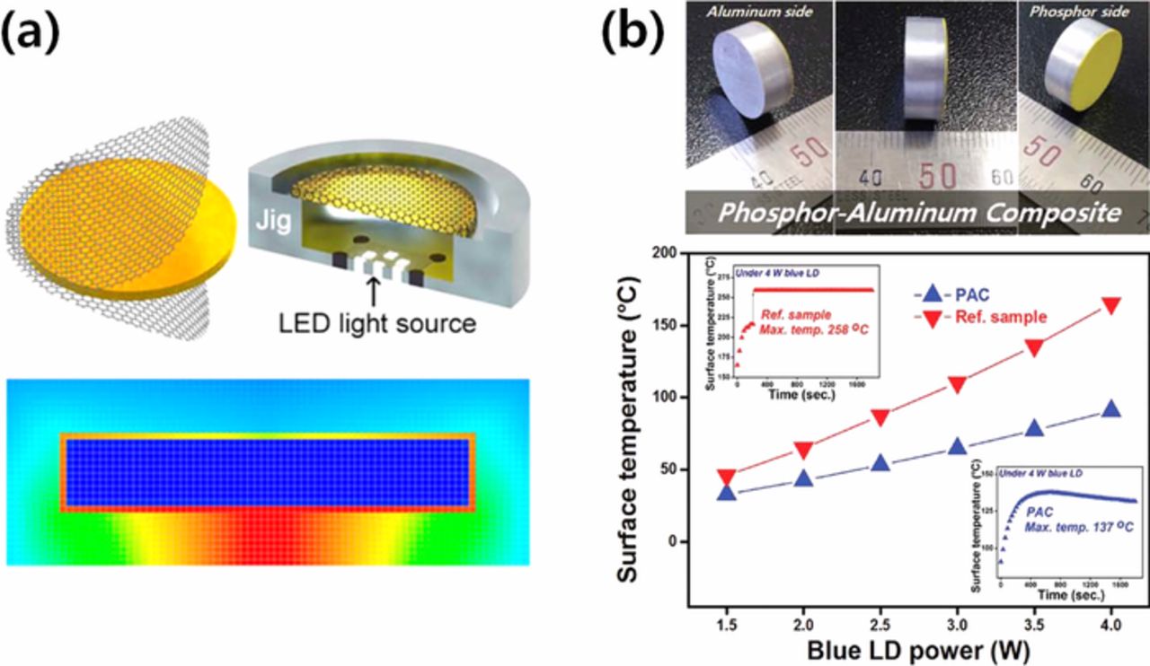
Figure 14. (a) Schematic diagram of PiG coated with graphene and its simulated result for heat dissipation (Reprinted with permission from Ref. 39. Copyright 2016 American Chemical Society). (b) Phosphor-aluminum composite and its surface temperature depending on the blue LD power (Reprinted with permission from Ref. 74. Copyright 2017 WILEY-VCH GmbH & Co.).
Other applications
Besides the high power LED applications, as discussed earlier, PiG can be used for the light source of displays such as LCDs, although further improvement is necessary for the color gamut to meet the requirements for high picture quality. Due to the robustness of PiG, it can be also applied to other lighting applications such as LEDs for artificial plant growth. Deng et al.54 synthesized PiG with 3.5MgO-0.5MgF2⋅GeO2:Mn4+ for deep red emission and observed an improved cultivation effect compared with the conventional LED due to its enhanced color stability as shown in Fig. 15a. Since PiG provides a flat surface along with a color converting property, it can be used as a substrate for organic LED (OLED) fabrication. Kim et al. fabricated a blue OLED on a YAG:Ce3+ PiG plate and demonstrated the potential of a color tunable all-in-one OLED as depicted in Fig. 15b.168 PiG has also been used as an efficient down converter to improve the conversion efficiency of perovskite solar cells with high UV stability.169
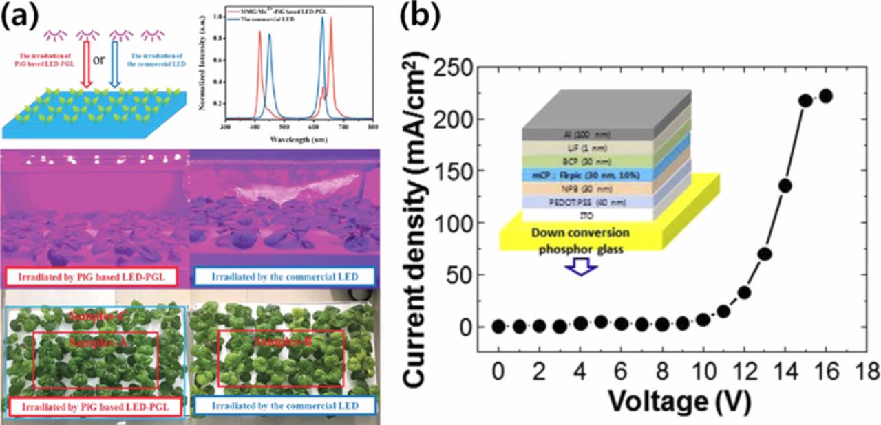
Figure 15. (a) Schematic diagram of indoor Chinese cabbage cultivation irradiated by different light sources and their actual photos after irradiation. (Reprinted with permission from Ref. 54. Copyright 2018 Royal Society of Chemistry.). (b) Schematic diagram of OLED stacked on a yellow PiG and its current density-voltage diagram (Reprinted with permission from Ref. 168. Copyright 2014 Elsevier B.V.).
If PiG contains a phosphor with deep-trap persistent luminescent materials, it can be used for multidimensional and rewritable optical information storage.117,170 As shown in Fig. 16a, information written in a blue laser is invisible and can be retrieved by high temperature thermal stimulation or photo-stimulation with other laser sources with different wavelengths. Li et al.170 synthesized a PiG film with Y3Al5-xGaxO12:Ce3+,V3+ (x = 0-3) and successfully demonstrated the optical writing with a 450 nm blue laser and read-out via heat-treatment at 250°C or photostimulation under 808 nm laser excitation as observed in Fig. 16.
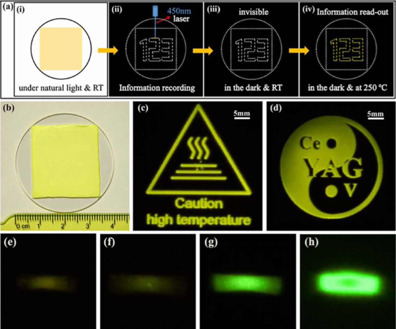
Figure 16. Optical information storage with PiG plate. (a) Schematic diagram of optical information recording and readout on a PiG film containing deep-trap persistent luminescence phosphors with heat-treatment. (b) Actual photographic image of a PiG film under natural light. (c,d) Photographic image of luminescent patterns readout from the PiG film after heating to 250°C in the dark. (e-h) Photographic images of luminescent patterns readout from the PiG films varying Ga-content in Y2.985Al4.998-xGaxO12:Ce0.015,V0.002 phosphor for x = 0 (e), 1 (f), 2 (g), 3 (h) under 808 nm laser photostimulation. The exposure time was 5, 5, 0.1, and 0.05s for (e-h), respectively. (Reprinted with permission from Ref. 170. Copyright 2018 American Chemical Society).
Summary
Phosphor in glass (PiG) is a simple mixture of phosphor and transparent glass and can be readily fabricated at a lower temperature than other inorganic color converters such as CPP. Due to its relatively low production cost and highly enhanced thermal and long-term stability compared with the conventional PiS, it has been successfully commercialized and is now a strong candidate for various applications which require color converters. Although various phosphors, including oxide, fluoride, sulfide, nitride, oxyfluoride, oxysulfide and oxynitride systems, can be incorporated within a glass matrix, phosphors need to avoid thermal degradation during the sintering process and thus commercial phosphors such as garnet based phosphors (YAG:Ce3+ or LuAG:Ce3+), CASN:Eu2+, Ca-α-SiAlON and β-SiAlON have been widely used for their high thermal stability. Various glass materials based on silicate, borate, phosphate, heavy metal oxide, tellurite and oxyfluoride systems have been synthesized to embed phosphors. The glass needs to be transparent after sintering and should have a low sintering temperature to prevent a possible reaction with phosphor and thermal degradation. Although several glasses based on heavy metal oxide, tellurite and oxyfluoride can be sintered at temperatures below 400°C and even as low as 230°C, they mostly have an inherent visible absorption or weak chemical and thermal stability, and thus silicate glasses seem to be more promising for commercial production for the moment. The conventional solid state sintering process, including powder mixing and packing processes, are normally used for PiG fabrication. GPS has been introduced to remove trapped pores within the glass matrix. Various fabrication methods have been suggested to overcome the shortcomings of the sintering process, such as screen printing, tape casting, SPS and sol-gel.
Various efforts have been made to improve the color conversion properties of the PiG with only YAG:Ce3+, such as chromaticity, CRI, CCT, LE, angle dependency and color gamut. Practical tunability of the color coordinate, CRI and CCT has been achieved by the combination of phosphors with different colors. For example, introduction of CASN:Eu2+ (red) to YAG:Ce3+ produced warm wLEDs with a high CRI. Various approaches have been developed to improve the LE of PiG packaged LEDs. Increased transparency of the glass matrix to reduce the trapped pores helped to increase the LE. Adjusting the refractive index of the glass matrix to make it close to that of phosphors improved the light extraction efficiency from phosphors and increased the LE. Enhancement of the light extraction efficiency has also been observed by geometrical modification of the PiG plate or thick films. Segmented or pattern structured PiG reduced the reabsorption of the neighboring phosphors, thus contributing to the resultant LE. The angle dependency of the CCT and chromaticity compensated for by the introduction of a diffusing agent or a patterned structure. The color gamut of the wLED with commercial phosphors has been improved by the Nd3+-ion modification of the emission spectrum.
PiG was developed for a robust color converter of a high power LED and was commercialized as an automotive headlamp in 2013. Due to its high reliability, PiG can be also applied to other automotive lighting systems, such as amber and red signals, as well as conventional high power lighting lamps. The stability of PiG has allowed the use of a high power LD as an excitation source for a laser headlamp module. PiG has also demonstrated its feasibility as a lighting source for LCD displays and plant growth. PiG has been used as a substrate for color tunable OLEDs and a down converter for perovskite solar cells with increased conversion efficiency. Optical information storage applying deep-trap persistent luminescent materials to PiG has also been proposed and suggests the high versatility and potential of PiG.
Although extensive studies have been carried out to improve fabrication methods and luminous properties, further studies are still necessary to extend its applications. For example, a proper glass system with high stability and a low sintering temperature below 400°C needs to be developed to incorporate more thermally vulnerable phosphors for their commercialization. Moreover, to compete with CPP and PiS, a practical fabrication method to reduce production cost and increase color homogeneity is needed. It is also very important to find new applications which can utilize the advantages of PiG. However, this survey suggests that PiG is the most promising material among various color converting materials and is expanding its market.
Acknowledgments
This work was supported by the National Research Foundation of Korea (NRF) grant funded by the Korea government (MSIT) (NRF-2019R1A2C1007621).
ORCID
Woon Jin Chung 0000-0002-1523-338X