
Abstract
In response to challenges in the thermal management of lithium-ion batteries (LIBs), we investigate the concept of circulating electrolyte through the porous electrodes and separator to facilitate effective, uniform, and real-time temperature regulation. We show, through physics-based electrothermal modeling and dimensional analysis of a single, planar LIB cell, that electrolyte convection can simultaneously draw heat from the cell and suppress heat generation from entropy change, charge-transfer, and ohmic losses, and that the cell temperature rise can be effectively mitigated when heat removal matches or exceeds heat generation. These findings distinguish internal convection from external surface cooling approaches used in conventional thermal management that often lead to a tradeoff between heat and mass transport. In a simulated exemplary 5.7-C case, a LIB cell with stationary electrolyte must stop discharging at only 54% of its capacity due to cell temperature rise to an upper threshold (325 K); with sufficient electrolyte flow (∼1 μm s−1 for a single cell, or a residence time of ∼200 s), the cell can be maintained below 315 K while delivering 98% of its capacity. Finally, to illustrate the potential for dynamic temperature regulation, we simulate scenarios where cells already experiencing self-heating can instantly arrest temperature rise with the onset of convection.

Export citation and abstract BibTeX RIS

This is an open access article distributed under the terms of the Creative Commons Attribution 4.0 License (CC BY, http://creativecommons.org/licenses/by/4.0/), which permits unrestricted reuse of the work in any medium, provided the original work is properly cited.
List of Symbols
| Symbol | Description |
| a | Particle surface area to volume |
| Ac.c. | Current collector cross-sectional area |
| Acell | Cell cross-sectional area |
| Atank | Tank total heat transfer surface area |
| Atube | Tube cross-sectional area |
| brugg | Bruggeman's coefficient |
| Cp | Heat capacity |

| Average cell heat capacity |
| Cp,e | Electrolyte heat capacity |
| ce (x,t) | Anion concentration in the electrolyte |
| cinitial | Initial electrolyte concentration |
| ctank(t) | Tank concentration |
 (x,t)
(x,t)
| Solid-phase surface concentration |
| cs max | Maximum solid-phase concentration |
| D | Electrolyte diffusivity |
| Deff | Effective electrolyte diffusivity |

| Effective solid-phase diffusivity |

| Solid-phase diffusivity |

| Solid-phase diffusion temperature dependent activation energy |

| Reaction rate constant temperature dependent activation energy |
| F | Faraday constant |
| hcell | Cell convective heat transfer coefficient |
| htank | Tank convective heat transfer coefficient |
| Iapp | Applied current density |
| j(x,t) | Ionic flux |
| keff,i | Effective reaction rate constant |
| ki | Reaction rate constant |
| L | Thickness |
| Lcell | Total cell thickness |
| n | Number of control volumes used |
| QA | Areal capacity |
| Qohm | Volumetric ohmic heat source term |
| Qrev | Volumetric reversible reaction heat source term |
| Qrxn | Volumetric irreversible reaction heat source term |

| Average volumetric heat generation rate |
| q | Tank input/output heat flux |
| R | Gas constant |
| Rp | Particle radius |
| Tambient | Ambient temperature |
| Tmax | Safety cutoff temperature |
| Tref | Reference temperature |
| Ttank | Tank temperature |
| Ttank,init | Tank initial temperature |
| T(x,t) | Cell temperature |
| tdis | Time to completely charge or discharge battery at Iapp |
| t+ | Li+ transference number |
| U | Open circuit potential |
| Vtank | Tank volume |
| v | Superficial velocity in the cell |
| vtube | Superficial velocity in the tube |
| ε | Porosity |
| εfiller | Filler fraction |
| η | Surface overpotential |
| Θ100% | Stoichiometry at 100% SoC |
| Θ0% | Stoichiometry at 0% SoC |
| κeff | Effective electrolyte conductivity |
| λ | Thermal conductivity |
| ρ | Density |

| Average cell density |
| ρe | Electrolyte density |
| σ | Solid-phase conductivity |
| σeff | Effective solid-phase conductivity |
| Φe | Electrolyte potential |
| Φs | Solid potential |
Lithium-ion (Li+) batteries (LIBs) are expected to play an important role in global decarbonization through their ubiquity in portable electronics and emergence in transportation and on the electric grid. 1,2 Over the last few decades, LIB prices have steadily decreased while energy density has increased due to a combination of material development, manufacturing improvements, and market scale. 3,4 However, current embodiments are still unable to meet the demanding performance, cost, and scale requirements of many new applications. 5,6 A notable challenge is thermal management, as for today's LIBs, typical operating temperatures between 15 °C and 40 °C are required to ensure optimal cell and battery performance, durability, and safety. 7 At elevated temperatures, accelerated solid-electrolyte interphase growth and component degradation can lead to capacity/power fade, 5,8 and, in the most extreme cases, thermal runaway and hazardous releases. At low temperatures, sluggish electrolyte transport and electrode reaction kinetics facilitate lithium plating and subsequent lithium dendritic growth on the negative electrode. 9,10 In addition, non-uniform temperature distribution leads to reaction maldistribution within the electrodes of individual cells and electrical imbalance between cells within the modules and packs, both of which reduce battery performance and cycle life. 10–12
To mitigate the adverse impacts of temperature, the battery thermal management system (BTMS) has become an essential component of the battery pack. Most current BTMS utilize an external strategy, where heat is exchanged through the exterior surfaces or tabs of the battery cells. Categorized by the heat transfer media (HTM), some common BTMS include air-, liquid-, and phase-change-materials (PCMs)-based approaches, each possessing benefits and limitations. 13,14 An air-based BTMS has merits such as simple structure, low cost, low weight, easy maintenance, and no leakage concern, but the low heat capacity and thermal conductivity of air limit its applicability for high-rate charge/discharge applications. 15,16 Comparatively, a liquid-based BTMS has greater thermal conductivity and heat capacity, leading to better heat transfer efficiency and compactness, and is hence a popular choice for space-constrained applications, such as battery electric vehicles (BEVs). 8,17,18 Among liquid-based systems, indirect methods that adopt water-glycol mixtures, nanofluids, or liquid metals as the HTM have been widely investigated. 8,13 While such solutions are relatively easy to implement, they rely on heat transfer auxiliaries such as cooling tubes or plates that add weight and complexity to the battery pack. Further, the additional heat resistance and confined contact area with the cell surfaces limits heat transfer efficiency. 13 Direct liquid systems that use a dielectric HTM, such as mineral oil, to contact the cells are emerging because, as compared to the aforementioned indirect methods, they enable simpler design, smaller footprints, and greater heat transfer rates. 19,20 However, the HTM suitable for these systems can be expensive as well as viscous and/or dense, leading to significant cost, power consumption, and added weight. 19 In recent years, PCM-based BTMSs have received considerable attention. 21,22 The PCM absorbs or releases a large amount of latent heat during phase transitions, resulting in a relatively constant temperature for the battery. However, most PCMs have poor thermal conductivities, which lead to low material utilization. 21 There is also a risk for thermal runaway in the case of complete melting, especially under harsh conditions, such as high charge/discharge rates and high ambient temperature. 23
In contrast to external thermal management approaches, there has been limited focus on methods of internal thermal management that regulate temperature from within the battery cell. Internal thermal management is most commonly used in battery preheating strategies, which leverage the heat generated from high resistances inside the cells from applying a current at low temperatures. 24,25 Over the past decade, only a few systems that utilize internal means of device cooling have been proposed. Bandhauer et al. developed a passive cooling approach for prismatic cells that used an internal evaporator with micro-channels integrated in a thick current collector. 26 A subset of the same authors then demonstrated through simulations that even though the pack volume increased due to the engineered current collector, the pack-level volumetric energy density for both charge and discharge was still greater than for a similar pack with external liquid cooling. 27 Mohammadian et al. proposed another internal cooling approach for prismatic cells in which liquid electrolyte served as a coolant, flowing through rectangular micro-channels embedded in the electrodes. 28 The authors showed that internal cooling not only effectively decreases the maximum temperature inside the cell, but enables a five-fold improvement in the temperature uniformity within the cell as compared to external liquid cooling at the same pumping power. 28 For cylindrical formats, several studies have contemplated a through-hole in the core of the cell to form an axial fluidic channel for liquid or gas coolants, or to embed a heat pipe or a thermally-conducting metal rod. 29–31 Such a configuration enables rapid heat dissipation especially in the center of the cell albeit with a minor reduction in cell capacity and energy density.
Despite the different configurations, all of the aforementioned internal and external cooling methods for LIBs have inherent shortcomings in thermal management due to their collective reliance on heat exchange with macroscopic surfaces. There is limited heat transfer area within the battery typically, and the introduction of new area inside a cell, for example, via pipes, channels, or rods mentioned above, leads to a loss of internal volume. High heat removal rates therefore require large amounts of cooling fluid, high flow rates, and/or significant pumping or fan power relative to overall battery system size and output. Additional disadvantages are spatial non-uniformity within a cell or pack, especially as battery size increases. Further, there is no access to the interior of electrodes and thus no benefit to transport to and from electrode material surfaces.
As an alternative approach, electrolyte can be directly circulated through the porous electrodes and separator of the electrochemical cell (Fig. 1b). A similar configuration was proposed for lead-acid batteries by Choi and Yao in 1979, who showed through simulation that electrolyte circulation can effectively maintain the cell temperature at a desired setpoint while providing a uniform temperature field. 32 For LIBs, such a cell configuration was proposed by Gordon and Suppes in 2013 as an approach to overcome electrolyte diffusion limitations, and is termed the convection battery. 33 Several subsequent reports have studied the benefits of incorporating forced electrolyte convection on mass transport via experiment and modeling. 33–36 Specifically, the circulating electrolyte reduces concentration gradients across the cell, thereby preventing salt depletion that adversely affects kinetic, ohmic, and transport resistances. This, in turn, leads to improvements in accessible capacity as well as energy and power density, especially under conditions of electrolyte mass transport limitations, such as high C-rate, thick electrodes, or low electrolyte diffusivity. 36 While an effective means of enhancing mass transport, forced electrolyte convection can also support battery thermal management, as it introduces convective heat transfer to the cell. Thus far, the impact of electrolyte convection on thermal regulation for LIBs has not been well-described. Initial investigation of thermal effects can be difficult to pursue experimentally, as it requires precise control and measurement of the heat fluxes; computationally, non-isothermal modeling provides a path to exploration given that the simultaneous impact of convection on electrolyte heat and mass transport may lead to further synergistic effects.
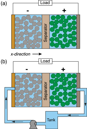
Figure 1. Lithium-ion battery configurations with (a) an enclosed cell design as is typical of contemporary devices and (b) the proposed flow-through concept that attempts to improve mass and thermal transport through electrolyte convection. The additional hardware required in (b) consists of an external storage tank, pump, and tubing or pipes to provide forced convection through the porous intercalation materials and separator that compose the battery cell. Note that (b) is presented solely for the purpose of illustrating the underlying concept and the model setup.
Download figure:
Standard image High-resolution imageHere, we aim to investigate the effect of a circulating electrolyte stream on thermal management through 1D modeling of a single LIB cell. Building upon prior work that employs isothermal modeling and dimensional analysis to elucidate the impact of electrolyte convection on mass transport, 36 we expand to temperature varying conditions to illustrate the impact of electrolyte convection on simultaneous mass and thermal transport. We first describe the model development including incorporation of a convective term into the governing cell heat balance equation, the modification of thermal boundary conditions at the current collectors, and the introduction of heat exchange equations between the electrolyte tank and the surrounding environment. We subsequently illustrate through three distinct case studies that electrolyte flow can suppress temperature rise in LIB cells that operate at high rates through a combination of reduced heat generation and increased heat removal. Accordingly, we derive dimensionless groups to describe key thermal transport processes that, along with their mass transport analogues, 36 describe conditions under which electrolyte convection can improve thermal management and the extent of these potential benefits. Lastly, we highlight the capability of electrolyte convection to dynamically regulate cell temperature through varying flow rate, which offers consideration of greater flexibility and responsiveness in thermal management.
Model Development
In our previous work, 36 we developed a convection cell model, LIONSIMBA+c, by extending the Li-ION SIMulation BAttery Toolbox (LIONSIMBA), 37 a pseudo two-dimensional (P2D) software package that has been validated against COMSOL MultiPhysics commercial software 38 and Newman's Fortran DUALFOIL. 39 By introducing a convection term to the governing electrolyte mass transport equation and including a continuity equation to describe the electrolyte tank, we were able to investigate the impact of electrolyte flow on cell performance as a function of component geometries, electrolyte properties, and cell operating conditions. The detailed descriptions of the modifications made, the governing equations, as well as the discretized approaches can be found in our prior open-access publication. 36 In this work, we expand the capabilities of LIONSIMBA+c to enable the study of thermal processes within a convection cell. Specifically, we (1) introduce a convection term into the governing heat balance equation for the electrodes and separator; (2) amend the boundary conditions to account for the flowing electrolyte at the inlet and outlet of the cell; (3) adjust the heat transport equation at both current collectors to account for the cell design change due to the addition of electrolyte tubing; and (4) incorporat energy conservation equations to track the electrolyte temperature within the external tank under a range of assumptions about its heat exchange mode with the surrounding environment including isothermal, adiabatic, ambient cooling, and constant heat flux input/output. We discuss the details of these changes below.
The original LIONSIMBA software package, developed by Torchio et al., 37 considers both isothermal and non-isothermal cell operation. For non-isothermal operation, the model adopts a general thermal treatment derived by Gu and Wang 40 to simulate the temperature change within a LIB cell. Similar to the description of electrolyte mass transport, the thermal model assumes that the cell temperature is radially uniform but that spatial temperature gradients can exist in the axial direction (x-direction in Fig. 1). An assumption underlying this approach is that the lateral walls of the cell are well-insulated, and heat exchange with the environment only occurs through the current collectors at either end of the cell (axial). It is also assumed that the different phases within the cell are in local thermal equilibrium, that is Tliquid (x, t) = Tsolid (x, t) = T(x, t). In LIONSIMBA+c, a convective term is introduced into the local heat balance within the electrodes and separator, as shown in Eq. 1.
Here, ρi , Cp,i , and λi are the density, heat capacity, and thermal conductivity of domain i, where i ∈ {p, s, n} indicates the positive electrode (p), separator (s), or negative electrode (n), respectively, T(x,t) is the temperature at position x and time t, ρe is the electrolyte density, Cp,e is the electrolyte heat capacity, and v is the superficial electrolyte velocity, which is assumed to be constant throughout the cell. While many possible sources of heat generation exist in a LIB cell, 41 the model considers three major contributors: (1) Qohm, the heat generation from ohmic resistance (Joule heating); (2) Qrxn, the irreversible reaction heat generation due to activation overpotential; and (3) Qrev, the reversible reaction heat generation due to entropy change. The expressions for these heat generation sources are refined based on the work by Srinivasan and Wang, 42 and provided in Appendix A·1. The current collectors exchange heat with the surrounding environment, yielding the same boundary conditions as the original model:


Here, λcu and λal are the thermal conductivities of the negative copper (cu) and positive aluminum (al) current collectors, respectively, hcell is the convective heat transfer coefficient of the cell, and Tambient is the temperature of the ambient environment external to and surrounding the cell, which is assumed to be constant at 298 K in this study. As shown in Fig. 1b, the convection cell configuration contemplated in this study assumes that the electrolyte flow enters and exits the electrochemical cell through tubes located at the center of the current collectors. For simplicity, we assume that, upon entering the cell, the flow is immediately uniformly distributed in the radial direction (cross-sectional plane perpendicular to the x-direction in Fig. 1), and that this uniformity is maintained until the exit (i.e., we do not consider any entrance or exit effects). We also assume the tubing between the cell and the tank is well-insulated and does not exchange heat with the surrounding environment or the current collectors. At the cell inlet and outlet, Danckwerts boundary conditions are implemented:
In Eqs. 4 and 5, Acell and Atube are the cross-sectional areas of the cell and the tube, respectively. The addition of the inlet/outlet tubes at the center of the current collectors necessitates modification of the heat transfer equation to account for the continuity in the output current:
Here, Ac.c. is the current collector cross-sectional area where Ac.c.+Atube = Acell, Iapp is the applied current density, and σi is the electrical conductivity of the current collectors. Note that variable current operation (Iapp as a function of time) is possible with LIONSIMBA+c, but is not pursued here. The temperature change inside the external electrolyte tank can be described as follows:

We assume that the tank is well-mixed with a volume Vtank and a total surface area Atank. Four different heat exchange conditions between the tank and the surrounding environment are considered in the model: (1) Isothermal, where the tank remains at its initial temperature at all times; (2) adiabatic, where the tank does not exchange heat with its surroundings, and any temperature change is only due to the electrolyte flowing into and out of the tank; (3) ambient cooling, where the surface of the tank exchanges heat with its surroundings via convective cooling, and htank is the convective heat transfer coefficient of the tank; and (4) constant input, where there is constant heat flux q into (q is positive) or out of (q is negative) the tank through its surface. The discretization of the thermal governing equations follows the approach described in prior work, 36 which uses the finite volume method (FVM) to partition the spatial domain into discrete volumes, while the convection term is treated with the upwind differencing scheme. Upon the aforementioned modifications, we compare simulated discharge curves using both LIONSIMBA and LIONSIMBA+c under non-isothermal conditions and with stagnant electrolyte (v = 0 μm s−1). As shown in Fig. S1 in the Supporting Information (SI), there is no difference between the model outputs across a range of C-rates, indicating that the modifications did not introduce artificial changes to the expected behavior.
The parameters used for the simulations performed in this study are shown in Table A·I. While this modeling framework can support the investigation of a wide range of component parameters and operating conditions, for clarity and tractability, we elect to study cell behavior under the following conditions. For all cell components, the literature-reported experimental values of ρi
, Cp,i
, and λi
are used.
43
Temperature-dependent physicochemical properties (e.g., electrolyte diffusion coefficient) are described using the relationships implemented in the original LIONSIMBA package,
37
which are shown in Appendix A·2. All the simulations were performed for galvanostatic operation, with a state of charge (SoC) range of 85.51% to 0.9%, a lower voltage limit of 2.5 V, and an upper temperature limit of 52 °C (325 K) based on the typical operating conditions and safety cutoffs for LIBs.
44
We used a cell cross-sectional area of 1 cm2 and an adiabatic tank with a volume of 50 ml for the simulations. The use of 1 cm2 is convenient for normalization and does not reflect a fundamental limitation of the model. Specifically, the findings described herein scale to cells of various areas subject to cross-sectional uniformity. The tube cross-sectional area is assumed to be 10% of the cell cross-sectional area, that is,  While LIONSIMBA+c makes it possible to specify distinct initial electrolyte concentrations and temperatures in the cell and tank, this work assumes the same initial electrolyte concentration of 1 M and same initial temperature of 25 °C (298 K) throughout the domain.
Model Analysis
Base case: conditions of significant thermal and mass transport limitations
To illustrate how the thermal effects impacts convection cell performance, we begin by repeating a base case analysis described in our prior work, 36 where the galvanostatic discharge of a single LIB cell with a stagnant electrolyte (v = 0 μm s−1) was simulated at 5.7C (150 A m−2 for a 26 Ah m−2 cell) under isothermal conditions. As shown in Fig. 2, we perform the same simulation while relaxing the isothermal assumption and allowing the cell temperature to vary freely. A small cell convective heat transfer coefficient (hcell = 0.5 W/(m2K)) is used to represent any background heat exchange between the cell and its surroundings. The discharge curve, Fig. 2a, shows that the accessible capacity without flow is just 54% of theoretical capacity. A large electrolyte concentration gradient develops across the cell during discharge due to the competing effects of diffusion and electromigration (Fig. 2b). However, with the inclusion of thermal processes, complete electrolyte salt depletion in the positive electrode is not realized by the end of the discharge, indicating that electrolyte mass transport limitation is not the sole cause of the abbreviated runtime. Rather, in the absence of electrolyte flow, the cell temperature increases rapidly upon discharge and reaches the cutoff (safety) temperature prior to electrolyte depletion (Fig. 2c). The rate of temperature rise can be slowed by convective flow, and for the single cell considered here, a superficial electrolyte velocity of 0.7 μm s−1 prevents the cell from hitting the cutoff temperature during discharge. For perspective, this flowrate for the single cell corresponds to a residence time of ∼290 s. Greater velocities further suppress cell temperature rise, and gradually reduce the electrolyte concentration gradient as well (Fig. 2b). Note that while the model simulates the cell temperature as a function of axial position, the temperature variation is negligible throughout the cell due to its thinness (Fig. S2). Thus, the temperature shown in Fig. 2c represents both the average cell temperature and the temperature at all positions and in all phases within the cell. Overall, Fig. 2 shows that the introduction of electrolyte flow simultaneously enhances mass and heat transport, both driving electrolyte concentration uniformity and mitigating cell temperature rise. It is noteworthy that, for the single cell analyzed in this study, overcoming the mass and thermal limitations requires electrolyte convection at similar scales, on the order of 1–10 μm s−1, for a near-uniform electrolyte concentration profile (Fig. 2b) and a temperature trajectory close to the initial cell temperature (Fig. 2c). In a battery format of greater thickness, such as multiple layers of the same single cell, the flow rate required to eliminate mass transport limitation would remain in the same order of magnitude as that for the single cell. However, a larger flow rate would be necessary to overcome thermal limitations. Nevertheless, for the scope of the current study, the corresponding pressure drop and resultant pumping losses across a single cell follow the estimates described in our previous study 36 and remain negligible compared to the energy gain on a per cell basis (Supplementary Note 1).

Figure 2. The effect of electrolyte convection on (a) the galvanostatic cell discharge (b) the concentration profile of electrolyte within the cell at t = 347 s, the end of discharge for the no flow case, and (c) the time-dependent trajectory of cell temperature. These results show the benefit of increasing flow rate on cell performance by minimizing the electrolyte concentration gradient while suppressing temperature rise. The corresponding heat generation data can be found in Fig. S3. Further discussions of the tank temperature change and the impacts of flow direction can be found in Supplementary Note 2 and Supplementary Note 3.
Download figure:
Standard image High-resolution imageDimensionless group development
Having demonstrated the case of benefit to runtime with both heat and mass transport effects, we present a generalized analysis of cell and component dimensions, component properties, and operational parameters where convection may prove advantageous. Compact and meaningful representation of cell performance as a function of individual cell properties and operating conditions can be challenging, as it often requires comprehensive parametric sweeps. Alternatively, combining the relevant physical parameters into dimensionless groups can provide insight on how the relative scales of different physical processes influence performance. For the single convection cell considered in this study, the temperature profile across the cell remains uniform. Hence, we limit our focus to dimensionless groups that describe the average cell temperature rise. To derive the dimensionless groups, we examine the overall cell heat balance equation: a
Next, we identify appropriate scales for the terms in Eq. 8. Applied current density and areal capacity provide a timescale of discharge,  Then, by approximating the cell temperature change from its initial temperature, Tinit, at t = 0, to a safety cutoff temperature, Tmax, at t = tdis, and the tank temperature with its initial temperature,
  , several useful quantities emerge: (1) the magnitude of ambient heat exchange rate of the cell,
  – in this case, the cell exchanges heat with the surrounding environment through the current collectors at either end of the device only; (2) the magnitude of convective heat exchange rate with the tank,
  (3) average heat generation rate,
  and (4) Average heat storage rate,
  The average volumetric heat generation rate,
  can be estimated using the cell parameters and operating conditions, as detailed in Supplementary Note 4; the multiplicative product of the average density,
  and the average heat capacity,
  can be calculated by averaging the ρCp
products of each cell component weighted by their respective thicknesses. Comparing these quantities yields the list of dimensionless groups that can be used to evaluate the average cell temperature gain (shown in Table I), which are subsequently denoted with the subscript H. To prevent any temperature rise, the heat removal rate from the cell must balance the heat generation rate within the cell. That is, the ratio of heat generation to heat removal must be small. In the case of an enclosed device (e.g., a conventional LIB cell) where heat removal relies on ambient heat exchange alone, this ratio is captured by the dimensionless parameter, γH
. A large γH
value indicates that the heat removal rate is insufficient, which, in turn, leads to temperature increases during charge or discharge. In the case of a convection cell, the electrolyte flow provides an additional mode of heat removal, and ξH
represents the ratio of the heat generation to the sum of heat removal via ambient cooling and electrolyte convection. In the absence of convection, γH
= ξH
. Similar to γH
, a large ξH
value indicates insufficient combined heat removal as compared to heat generation. Finally, the inherent buffering ability of the cell against heat generation is captured by βH
, where a large value indicates the cell is more prone to temperature increase for a given amount of heat generation. The dimensionless groups for mass transport, derived in our prior work,
36
are also included in Table I for reference and comparison, and are subsequently denoted with the subscript M. These groups are analogous to those used to describe heat transport. Specifically, γM
compares the electromigrative and diffusive fluxes, where a large value of this parameter indicates an increased likelihood for electrolyte salt depletion in the positive electrode during discharge due to insufficient diffusive transport. ξM
compares the electromigrative flux to the sum of diffusive and convective fluxes, where large values of this variable indicates that the combination of diffusive and convective fluxes are slower than the electromigrative flux that removes anions from the cathode. βM measures the buffering ability of the cell against electrolyte salt depletion, and a large value of this quantity indicates that the initial amount of salt in the electrolyte is insufficient compared to the depletion by the electromigration of the anions.
can be calculated by averaging the ρCp
products of each cell component weighted by their respective thicknesses. Comparing these quantities yields the list of dimensionless groups that can be used to evaluate the average cell temperature gain (shown in Table I), which are subsequently denoted with the subscript H. To prevent any temperature rise, the heat removal rate from the cell must balance the heat generation rate within the cell. That is, the ratio of heat generation to heat removal must be small. In the case of an enclosed device (e.g., a conventional LIB cell) where heat removal relies on ambient heat exchange alone, this ratio is captured by the dimensionless parameter, γH
. A large γH
value indicates that the heat removal rate is insufficient, which, in turn, leads to temperature increases during charge or discharge. In the case of a convection cell, the electrolyte flow provides an additional mode of heat removal, and ξH
represents the ratio of the heat generation to the sum of heat removal via ambient cooling and electrolyte convection. In the absence of convection, γH
= ξH
. Similar to γH
, a large ξH
value indicates insufficient combined heat removal as compared to heat generation. Finally, the inherent buffering ability of the cell against heat generation is captured by βH
, where a large value indicates the cell is more prone to temperature increase for a given amount of heat generation. The dimensionless groups for mass transport, derived in our prior work,
36
are also included in Table I for reference and comparison, and are subsequently denoted with the subscript M. These groups are analogous to those used to describe heat transport. Specifically, γM
compares the electromigrative and diffusive fluxes, where a large value of this parameter indicates an increased likelihood for electrolyte salt depletion in the positive electrode during discharge due to insufficient diffusive transport. ξM
compares the electromigrative flux to the sum of diffusive and convective fluxes, where large values of this variable indicates that the combination of diffusive and convective fluxes are slower than the electromigrative flux that removes anions from the cathode. βM measures the buffering ability of the cell against electrolyte salt depletion, and a large value of this quantity indicates that the initial amount of salt in the electrolyte is insufficient compared to the depletion by the electromigration of the anions.
Table I. Dimensionless groups quantifying the extent of bulk mass and thermal transport limitations.
| Dimensionless group | Meaning | Mass transport [M] | Heat transfer [H] ( ) ) |
|---|---|---|---|
| γ | Inherent transport ability |

|
|
| ξ | Transport ability with convection |

|
|
| β | Buffering ability |

|

|
The corresponding dimensionless group values of the Base Case are shown in Table II, column (a). The large values for all the four dimensionless groups indicate that, under these conditions and in the absence of convection, the inherent mass and thermal transport properties are insufficient to support the high discharge rate of 5.7C in a cell of these dimensions. This deficiency explains the large electrolyte concentration gradient and rapid temperature increase shown in Figs. 2b and 2c, respectively.
Table II. Mass [M] and heat [H] transport dimensionless group values for the cases demonstrated in (a) Base Case (b) Diffusive Transport Limited Case and (c) Thermal Transport Limited Case. The electrolyte properties at room temperature are used for the mass transport dimensionless group calculations.
| (a) Base case | (b) Diffusive transport limited | (c) Thermal transport limited | |
|---|---|---|---|
| γM | 2.4 | 2.4 | 2.4 × 10⁻³ |
| βM | 19.6 | 19.6 | 19.6 |
| γH | 3.0 | 3.0 × 10⁻³ | 2.1 |
| βH | 3.6 | 3.6 | 2.5 |
While the Base Case demonstrates that the introduction of electrolyte convection enables simultaneous enhancement of mass and heat transport, further investigation is needed to decouple and elucidate the impact of convection on each process. This can be achieved by contemplating two extensions of the Base Case: (1) Diffusive Transport Limited Case, where without convection, the cell has adequate heat transfer capabilities but the same poor mass transport properties and conditions used in the Base Case, and (2) Thermal Transport Limited Case, where the mass transport in the cell without convection is sufficiently facile, but the heat transfer rates are restricting. The following sections discuss the findings from these two alternative cases.
Diffusive transport limited case
In the first scenario, to focus on a diffusion limited case, we consider a cell with a convective heat transfer coefficient (hcell = 500 W/(m2K)) large enough to facilitate thermal transport to the point that the increase in cell temperature during discharge is negligible (Fig. S4), while all other conditions remain identical to the Base Case. The corresponding dimensionless group values are shown in Table II, column (b). The heat transfer coefficient value chosen here is representative of an indirect liquid cooling system.
45
This case corresponds to a cell with external heat removal capability sufficient to maintain near-isothermal operation (e.g., a highly effective thermal regulation system), which approaches the isothermal base case described in our prior work.
36
In the absence of an elevated average cell temperature, which increases diffusion rates, electrolyte mass transport presents significant limitations, but this can be alleviated by increasing electrolyte convection (or decreasing ξM
value) as shown in Fig. 3a. Enhanced electrolyte mass transport rates also positively impact the thermal regulation of the cell. As shown in Fig. 3b, reduced electrolyte concentration gradients facilitate more uniform reversible heat generation, suggesting improved reaction homogeneity particularly within the Li-ion-consuming electrode (here, the positive electrode). Importantly, this observation implies that electrolyte convection may help mitigate reaction maldistribution that limits power output and capacity utilization of thick electrodes in energy-dense cells.
46
Furthermore, electrolyte convection can reduce irreversible reaction heat generation in the positive electrode and overall Joule heating as shown in Figs. 3c and 3d, respectively. As convection enables higher electrolyte concentration in the positive electrode facilitating the charge transfer reaction, the activation overpotential required to sustain a desired current output is reduced thus lowering irreversible reaction heat generation. Moreover, a uniform ∼1 M electrolyte concentration across the cell decreases Joule heating by lowering ohmic losses (high ionic conductivity). Collectively, these results demonstrate that electrolyte flow can enable greater spatial uniformity in heat generation as well as reduce overall heat generation within a cell. In this case, the average volumetric heat generation rate ( ) is halved at 10 μm s−1 as compared to stagnant operation. As previously mentioned, the cell temperature gain is determined by both the rate of heat generation and the rate of heat removal. It is this ability to decrease heat generation via electrolyte flow that differentiates the convection approach from other external and internal thermal regulation methods that are solely designed to enhance heat removal rates. The reduction in heat generation through convection appears unique amongst reported BTMS and relaxes the requirement for heat removal capability in the first place.

Figure 3. Diffusive transport limited case (a) distributions of concentration and contributions to (b) reversible heat generation, (c) irreversible reaction heat generation, and (d) Joule heating. The figures are taken at t = 100 s, before complete electrolyte salt depletion occurs. The Joule heating in the current collectors is negligible and not shown.
Download figure:
Standard image High-resolution imageThermal transport limited case
In the second scenario, we consider a cell without mass transfer limitations by invoking a very large electrolyte diffusivity (D = normal value × 103
) with all other conditions the same as the Base Case. While, to the best of our knowledge, such diffusive rates are infeasible in practical electrolytes, the simulated conditions are instructive as they enable isolation of the effects of electrolyte convection on heat transfer. The corresponding dimensionless group values are shown in Table II, column (c). The γH
and βH
values are both slightly lower than Base Case values as the augmented diffusivity leads to more uniform electrolyte concentration across the cell, reducing the activation overpotential and thus diminishing the heat generation rate,  This result is analogous to that obtained when simulating increased electrolyte flow rate in the previous case. This effect is clearly observable in Fig. 4, where even without electrolyte flow, the cell can discharge for a longer time as compared to its counterpart in Fig. 2c. With the introduction of electrolyte flow, the temperature rise is further suppressed, and when ξH
 1, the cell can be fully discharged, accessing almost all of the available charge storage capacity, without hitting the upper threshold. Thus, Fig. 4 evinces the second effect of electrolyte flow on thermal management, namely that bulk flow can remove heat from the cell to prevent temperature increase (i.e., boosting the heat removal capability of the cell). Additionally, consistent with physical intuition, a transition value of ξH
 1 means that the heat generation rate
  the heat removal rate. As a heuristic, the amount of flow required to prevent the cell from hitting the cutoff temperature can be estimated from ξH
= 1, and the remaining parameters defining this dimensionless group in Table I. Note that although a single cell (∼200 μm) is demonstrated in this study, ξH
is also applicable to a larger battery format, which suggests that the flowrate needed to suppress average temperature rise roughly scales with the system dimension in the direction of flow. Also note that while convection can effectively prevent the cell temperature gain, it may be desirable for the cell to operate at a set temperature above or below the ambient conditions.
47,48
This may be to promote favorable reaction kinetics and/or mass transport characteristics, to heat a device in cold climes, or to cool a device subjected to excessive heat due to local weather conditions or proximity to an external heat source. A non-ambient target temperature can be achieved by regulating the flow rate and/or introducing electrolyte pre-conditioned at a different inlet temperature.
the heat removal rate. As a heuristic, the amount of flow required to prevent the cell from hitting the cutoff temperature can be estimated from ξH
= 1, and the remaining parameters defining this dimensionless group in Table I. Note that although a single cell (∼200 μm) is demonstrated in this study, ξH
is also applicable to a larger battery format, which suggests that the flowrate needed to suppress average temperature rise roughly scales with the system dimension in the direction of flow. Also note that while convection can effectively prevent the cell temperature gain, it may be desirable for the cell to operate at a set temperature above or below the ambient conditions.
47,48
This may be to promote favorable reaction kinetics and/or mass transport characteristics, to heat a device in cold climes, or to cool a device subjected to excessive heat due to local weather conditions or proximity to an external heat source. A non-ambient target temperature can be achieved by regulating the flow rate and/or introducing electrolyte pre-conditioned at a different inlet temperature.
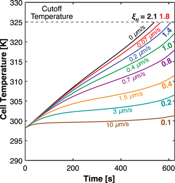
Figure 4. Thermal transport limited case temperature profile over time. The use of a large electrolyte diffusivity (D = normal value × 103) yields a uniform electrolyte concentration profile even in the absence of electrolyte flow (Fig. S5). Thus, the suppression of temperature gain by increasing flow rate is solely due to increased rates of heat removal and no effect on heat generation.
Download figure:
Standard image High-resolution imageComparison between internal and external cooling
The analyses above illustrate the unique advantages that a flowing electrolyte offers through simultaneous improvement of mass and heat transport with one of the two limitations significantly relaxed. Now we directly compare the impact of convection (hereafter referred to as "internal cooling") and the typical external thermal management methods (hereafter referred to as "external cooling") on temperature regulation and cell performance, with no upfront relaxation of any transport limitation. We use the same cell configuration and discharge conditions as in the Base Case. For external cooling, the cell exchanges heat with the surrounding environment through the axial ends (i.e., the current collectors), with a total representative heat exchange rate of  For internal cooling, electrolyte flows through the cell in the direction shown in Fig. 1b (from the negative electrode to the positive electrode) and exchanges heat with the tank at a representative heat exchange rate,
  Equivalent heat removal rates are anticipated for the external and internal modes when the two heat exchange rates are equal, as is shown in Supplementary Note 5. However, as Fig. 5 demonstrates, an "equivalent" set of v and hcell values yields the same heat removal capability yet different impact on cell temperature regulation and thus performance. With external cooling, the first increments in hcell value help extend the cell runtime (Fig. 5a) by inhibiting temperature rise (Fig. 5c) and prolonging or avoiding the 325 K cutoff. However, without internal convection, mass transfer relies upon temperature-dependent diffusion alone, and further increases in hcell values have an adverse effect on mass transfer. A lower average cell temperature results in slower electrolyte mass transport (Fig. 5b) leading to lower cell operating voltage (reduced power density), and even shortens the cell runtime as electrolyte salt depletion increases at higher hcell values. Hence, for external cooling, increasing heat removal capability (i.e., increasing hcell) improves thermal transport but compromises mass transport; if the cell has a large electrolyte mass transport resistance (i.e., large γM
and βM
values), such as the case shown in Fig. 5, increasing hcell values will ultimately cause the cell to transition from thermal-transport-limited behavior to diffusive-transport-limited behavior. This compromise is in contrast with the internal cooling, where increasing heat removal capability (i.e., increasing v) results in simultaneous heat and mass transport enhancement, as shown in Figs. 5d–5f, ensuring that neither bulk transport mode hinders cell performance at sufficient v.
Equivalent heat removal rates are anticipated for the external and internal modes when the two heat exchange rates are equal, as is shown in Supplementary Note 5. However, as Fig. 5 demonstrates, an "equivalent" set of v and hcell values yields the same heat removal capability yet different impact on cell temperature regulation and thus performance. With external cooling, the first increments in hcell value help extend the cell runtime (Fig. 5a) by inhibiting temperature rise (Fig. 5c) and prolonging or avoiding the 325 K cutoff. However, without internal convection, mass transfer relies upon temperature-dependent diffusion alone, and further increases in hcell values have an adverse effect on mass transfer. A lower average cell temperature results in slower electrolyte mass transport (Fig. 5b) leading to lower cell operating voltage (reduced power density), and even shortens the cell runtime as electrolyte salt depletion increases at higher hcell values. Hence, for external cooling, increasing heat removal capability (i.e., increasing hcell) improves thermal transport but compromises mass transport; if the cell has a large electrolyte mass transport resistance (i.e., large γM
and βM
values), such as the case shown in Fig. 5, increasing hcell values will ultimately cause the cell to transition from thermal-transport-limited behavior to diffusive-transport-limited behavior. This compromise is in contrast with the internal cooling, where increasing heat removal capability (i.e., increasing v) results in simultaneous heat and mass transport enhancement, as shown in Figs. 5d–5f, ensuring that neither bulk transport mode hinders cell performance at sufficient v.

Figure 5. Comparison of external cooling (left plots) and internal convective cooling (right plots) on three (3) key outputs: galvanostatic discharge curves (a), (d), electrolyte concentration distributions (b), (e) at 269 s, the end of the shortest discharge (hcell = 12.9 W/(m2K)), and transient temperature trajectories (c), (f). Each curve on the left has a corresponding curve on the right of the same color with equal heat removal rate. Internal cooling shows improvements in these 3 key outputs with successive increasing flow rates. However, with external cooling, cell behavior shifts from thermal to mass transport limited ultimately leading to truncated discharge at the highest heat removal rate simulated.
Download figure:
Standard image High-resolution imageThe contrasting impact of the two cooling strategies on electrolyte mass transport has further implications on their efficacy. As discussed in the Diffusive Transport Limited Case, improved electrolyte mass transport, such as with internal cooling, leads to diminished heat generation rates due to reduced overpotential losses. Conversely, heat removal with external cooling decreases electrolyte mass transport and therefore increases heat generation as shown in Fig. S6. Consequently, internal cooling suppresses cell temperature rise more effectively than external cooling even with the same heat removal capability, as observed by comparing Figs. 5c with 5f. This implies that compared to external cooling, the heat removal capability required of internal cooling is lowered due to the reduced amount of heat generation. This finding further supports the argument that through enhanced electrolyte mass transport, the internal cooling method offers unique advantages over external cooling methods by both removing heat (heat transfer) and reducing heat generation (mass transfer), resulting in greater effectiveness.
The comparison between internal and external cooling discussed here is not limited to a single cell of ∼200 μm thickness but is also applicable to larger systems, such as multiple cell layers. However, in these cases, the effect of temperature gradient becomes significant and should be considered for the design with both cooling strategies. Regarding the internal cooling strategy, the temperature gradient is mainly present in the direction of flow and is closely related to the system design/configuration and resultant flow path, which are beyond the scope of this initial work. Nevertheless, the temperature gradient can be significantly reduced or become negligible at high flow rates. As such, the findings presented here represent the full potential of electrolyte flow (i.e., the performance of an optimized system) and provide a basis for future work on system development.
On the potential for dynamic thermal regulation via varying electrolyte flow rate
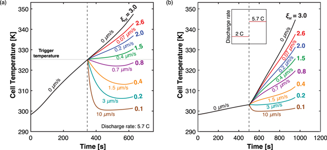
The ability to modulate electrolyte flow rate during convection cell operation offers new opportunities to dynamically regulate cell performance. While many different and specific scenarios could be considered, we contemplate two general approaches in Fig. 6. In the first scenario, as shown in Fig. 6a, we illustrate a reactive approach where electrolyte convection is triggered by a cell safety temperature (in this example 325 K), and a sufficient flow rate (that satisfies ξH
 1) suppresses the temperature rise almost instantaneously. In practice, this scenario may correspond to urgent rescue situations, such as thermal runaway protection. Interestingly, the higher flow rates (0.7–10 μm s−1) have convex temperature profiles, where the temperature drops immediately upon the introduction of flow, but given sufficient time, gradually increases again. This is because as the cell temperature reduces, the heat removal rate decreases to the point where it is less than the heat generation rate and the cell temperature begins to increase again. In a second scenario, we show a proactive approach where the flow rate is changed based on operating conditions. As shown in Fig. 6b, electrolyte convection is simultaneously introduced when there is a change in C-rate. This corresponds to a situation where a rapid change in battery power is required during operation, such as, a sudden acceleration in a BEV. The ξH
values calculated for this scenario are based on 5.7 C and a cutoff temperature of 325 K, so a flow rate that suffices ξH
1) suppresses the temperature rise almost instantaneously. In practice, this scenario may correspond to urgent rescue situations, such as thermal runaway protection. Interestingly, the higher flow rates (0.7–10 μm s−1) have convex temperature profiles, where the temperature drops immediately upon the introduction of flow, but given sufficient time, gradually increases again. This is because as the cell temperature reduces, the heat removal rate decreases to the point where it is less than the heat generation rate and the cell temperature begins to increase again. In a second scenario, we show a proactive approach where the flow rate is changed based on operating conditions. As shown in Fig. 6b, electrolyte convection is simultaneously introduced when there is a change in C-rate. This corresponds to a situation where a rapid change in battery power is required during operation, such as, a sudden acceleration in a BEV. The ξH
values calculated for this scenario are based on 5.7 C and a cutoff temperature of 325 K, so a flow rate that suffices ξH
 1 suggests that the cell will not reach the cutoff temperature of 325 K. If minimal temperature rise is desired, a smaller cutoff temperature (e.g., 300 K) could be used to calculate a corresponding flow rate that yields ξH
= 1.
1 suggests that the cell will not reach the cutoff temperature of 325 K. If minimal temperature rise is desired, a smaller cutoff temperature (e.g., 300 K) could be used to calculate a corresponding flow rate that yields ξH
= 1.
Figure 6. Demonstration of dynamic flow rate for thermal regulation. In reactive mode (a), convection is triggered by a safety temperature (e.g., thermal runaway protection); in proactive mode (b), convection is triggered by a change in current density (e.g., sudden acceleration in a BEV).
Download figure:
Standard image High-resolution image
Importantly, variable "on-demand" convection instead of continuous flow allows the system to forgo convection when not needed, such as for low current charge or discharge, for intentional self-heating, or for pumping energy savings. Reactive mode (Fig. 6a) can tune the use of flow to critical situations only, but precise effectiveness of this mode may rely on accurate temperature measurements of the cells within a battery pack. The proactive use of flow coordinated with a significant increase in heat generation, for example, in Fig. 6b, can prevent temperature escalation in advance or when difficult to reliably measure. However, the proactive scenario may call for flow prematurely or when unnecessary, such as, if high heat generation operation is aborted.
Conclusions
Effective thermal management remains key to enabling emerging applications of LIBs, particularly those that require high power input and output (such as BEV fast charging, electric aviation), or need large battery formats (e.g., stationary storage systems). In this work, we investigated a unique internal cooling strategy, where the electrolyte is directly circulated through the porous electrodes and separator of a LIB cell. We expanded upon our prior isothermal model, LIONSIMBA+c, to incorporate convective heat transfer. Through the modeling and analysis of a single LIB cell (∼200 μm), we illustrated the impact of electrolyte flow on thermal management, which lays a foundation for the consideration of larger, practical systems. To summarize our findings, we showed that the electrolyte flow can effectively suppress temperature rise in a single LIB cell operating at high C rates, and elucidated its dual effects on thermal management: (1) electrolyte flow reduces heat generation rate through the elimination of the electrolyte concentration gradient, and through the resulting decreases in activation, ohmic, and concentration overpotentials; (2) the bulk electrolyte flow enhances heat removal rate by directly carrying the generated heat out of the cell. To aid interpretation and understanding between the balance of heat generation, heat storage, and heat removal, we derived three dimensionless groups, βH
, γH
, and ξH
, that characterize the simulation results, which parallel our prior list of dimensionless groups for mass transport processes.
36
In summary, electrolyte convection is most beneficial to introduce to cells with insufficient heat capacity and heat removal relative to heat generation, which is represented by large βH
and γH
values. The dimensionless group, ξH
, compares the heat generation rate to the total heat removal rate including electrolyte convection, and can help determine the flow needed to prevent the cell from reaching the safety cutoff temperature. The temperature rise of a cell can be curbed through the balance of heat generation by heat removal, as represented by ξH
 1. It should be emphasized that the dimensionless groups developed in this study are not restricted to single cells. The group, ξH
, for instance, scales with thickness and can provide estimates for larger energy storage devices composed of multiple cell layers as well.
1. It should be emphasized that the dimensionless groups developed in this study are not restricted to single cells. The group, ξH
, for instance, scales with thickness and can provide estimates for larger energy storage devices composed of multiple cell layers as well.
Electrolyte convection has favorable effects on cell transport behavior that differ from existing approaches. Cooling strategies to date focus nearly exclusively on improving heat removal, which can lead to increased heat generation rates due to reduced mass transport at lower temperatures. In some cases, this sacrifice of transport properties shifts the cell from thermal-transport-limited to mass-transport-limited regimes. In contrast, the cooling strategy proposed here offers synergistic enhancement of heat and mass transport, which results in more effective thermal management, as it not only improves heat removal capability, but also reduces heat generation in the first place. This method also offers opportunities for dynamic temperature regulation through readily adjustable electrolyte flow rate and temperature. One application of particular interest is the cell operation at a slightly elevated but stable temperature for improved kinetic and transport properties without compromising safety.
While this work focuses on the scale of a single cell (∼200 μm thickness, 1 cm2 area), we expect the reduction in heat generation and improved heat removal with electrolyte convection would play a signification role in larger embodiments (such as thicker electrodes, greater area cells, and multi-cell configurations). The dimensionless groups on thermal and mass transport derived in this and prior work 36 can be used to guide the design of convection battery prototypes. Nevertheless, transforming this concept into a scaled prototype requires considerations beyond those discussed here. As ξH suggests, the flowrate needed to suppress the temperature rise roughly scales with the system dimension in the direction of flow. For the single cell studied here, pumping loss is negligible, but this may change for a larger system that relies solely on electrolyte flow for heat removal. Furthermore, when the flow path is longer, the temperature gradient can become significant at intermediate flow rates. The design of the electrolyte storage tank is also crucial, as a bigger tank may increase heat removal efficacy, but it could come at the cost of system energy density. Such factors and tradeoffs should be carefully evaluated in future work on system design and optimization. In addition, the cost and availability of technology innovation and additional hardware to enable fluidic distribution across high aspect ratio flow through porous electrodes, as well as the potential benefits in terms of improved performance and cost savings, should be carefully considered. It is worth noting that, compared to external liquid-based BTMS, this concept presents an opportunity to explore a simplified balance of plant that could include the elimination of external cooling pipes and plates, which warrants further investigation. Future research should incorporate both technical and economic analyses to ensure the practicality and scalability of this concept in real-world applications.
Acknowledgments
The authors gratefully acknowledge funding from ExxonMobil through the MIT Energy Initiative. W.G. gratefully acknowledges the MathWorks Engineering Fellowship through the MIT Department of Chemical Engineering. J.D. gratefully acknowledges the MIT MLK Visiting Professors and Scholars Program. The authors also thank Trent Weiss of the Brushett Group for insightful discussions. Interested researchers can contact the authors for additional information about the model used in this study and to address inquiries related to the underlying code.
CRediT Authorship Contribution Statement
Weiran Gao: Conceptualization, Methodology, Software, Validation, Formal analysis, Investigation, Writing - Original Draft, Writing - Review & Editing, Visualization; Javit Drake: Conceptualization, Methodology, Formal analysis, Writing - Review & Editing; Fikile R. Brushett: Conceptualization, Methodology, Formal analysis, Resources, Writing - Review & Editing, Supervision, Project administration.
Appendix
A·1. Heat source terms
where 

where 

A·2. Temperature-dependent values and properties
A·2·1. Open circuit potential


Where 

Where 
A·2·2. Effective electrolyte diffusion coefficient

A·2·3. Effective electrolyte conductivity
A·2·4. Effective reaction rate
A·2·5. Effective solid-phase diffusion coefficient
Table A·I. Simulation parameters used in this study.
| Units | Positive CC | Positive electrode | Separator | Negative electrode | Negative CC | |
|---|---|---|---|---|---|---|
| — | Al | Liθ CoO2 | — | Liθ C6 | Cu | |
| a | m2/m3 | — | 862500 | — | 851100 | — |
| brugg | — | — | 2.5 | 2.5 | 2.5 | — |
| Cp | J/kg/K | 903 | 1269 | 1978 | 1437 | 385 |
| Cp,e | 2055 J kg−1 K−1 | |||||
| cinitial | mol m−3 | — | 1000 | 1000 | 1000 | — |
| cs max | mol m−3 | — | 51554 | — | 30555 | — |

| m2 s−1 | — | 1 × 10–14 | — | 3.9 × 10⁻¹⁴ | — |

| J mol−1 | — | 5000 | — | 5000 | — |

| J mol−1 | — | 5000 | — | 5000 | — |
| F | 96487 C mol−1 | — | — | — | — | — |
| Iapp | 150 A m−2 | |||||
| ki | m2.5/(mol0.5s) | — | 2.334 × 10⁻¹¹ | — | 5.031 × 10⁻¹¹ | — |
| L | m | 1 × 10⁻⁵ | 8 × 10⁻⁵ | 4 × 10⁻⁵ | 8 × 10⁻⁵ | 1 × 10⁻⁵ |
| n | — | 12 | 100 | 50 | 100 | 12 |
| R | 8.314 J mol−1 K−1 | — | — | — | — | — |
| Rp | m | — | 2 × 10⁻⁶ | — | 2 × 10⁻⁶ | — |
| t+ | 0.37 | |||||
| ε | — | — | 0.4 | 0.4 | 0.4 | — |
| εfiller | — | — | 0.025 | — | 0.0326 | — |
| Θ100% | — | — | 0.4955 | — | 0.8551 | — |
| Θ0% | — | — | 0.9917 | — | 0.0066 | — |
| λ | W/m/K | 238 | 1.58 | 0.33 | 1.04 | 398 |
| ρ | kg m−3 | 2702 | 2329 | 1009 | 1347 | 8933 |
| ρe | 1130 kg m−3 | |||||
| σ | S m−1 | 3.55 × 10⁷ | 100 | — | 100 | 5.96 × 10⁷ |
Footnotes
- a
Cell thermal energy accumulates or depletes from internal heat generation and net fluxes at the boundaries—convection from the tank and ambient heat exchange. Mathematically, this emerges from integration of the local heat balance, Eq. 1, and substitutions from the subsequent equations.
Supplementary data (8.1 MB DOCX)