
Abstract
Bright white plasma electrolytic oxidation (PEO) films with uniform maze-like structures were obtained by anodizing Al in an ammonium tetraborate solution. High-purity Al plates were galvanostatically anodized in 0.3–2.4 M ammonium tetraborate solutions at 303–343 K and 10–100 Am−2. A PEO film consisting of an outer porous layer consisting of amorphous alumina and crystalline alumina with α-and γ-phases and an inner amorphous barrier alumina layer was obtained on the Al surface. An extremely uneven PEO film with various pore sizes and many cracks was formed in a 0.3 M ammonium tetraborate solution, whereas a relatively uniform porous PEO film with similar pore sizes was obtained in 0.9–2.4 M solutions. This difference in the PEO film morphology was due to the plasma generation behavior while anodizing. The lightness of the PEO film increased with increasing anodizing time and PEO film thickness; thus, a bright white PEO film measuring 87.5 in lightness (L*) was formed on the Al surface. The water wettability of the PEO film exhibited weak hydrophilicity. Moreover, a superhydrophobic PEO film with a contact angle of 154° was easily fabricated by self-assembled monolayer modification. Similar bright white PEO coatings were successfully fabricated on various industrial alloys.

This is an open access article distributed under the terms of the Creative Commons Attribution 4.0 License (CC BY, http://creativecommons.org/licenses/by/4.0/), which permits unrestricted reuse of the work in any medium, provided the original work is properly cited.
Electrochemical anodizing of Al in suitable aqueous electrolyte solutions enables the formation of several types of anodic oxide films on surfaces. 1–5 Porous anodic oxide films with a nanoscale honeycomb structure that are less than 1 μm to more than 100 μm in thickness can be easily obtained by anodizing in acidic or alkaline solutions. 6–14 Porous oxide films with hydrated oxide are typically used to provide corrosion protection to Al alloys. 15–19 In addition, this characteristic honeycomb nanostructure has been recently used for various nanoapplications, such as nanofilters, nanotemplates, and optical nanodevices. 20–29 Moreover, high-density fibrous anodic oxides measuring several tens of nanometers or less than 10-nm in diameter can be fabricated by long-term anodizing due to the selective dissolution of porous oxides. 30–33 These fibrous oxides have been used for the wettability control of Al surfaces, such as the fabrication of superhydrophilic and superhydrophobic Al surfaces. 34,35 Barrier anodic oxide films with a flat, thin morphology measuring several hundred nanometers in maximum thickness can be fabricated by anodizing in neutral solutions, and these films are widely employed as dielectric films of electrolytic capacitors in various electric appliances. 36,37 The excess anodizing process at higher voltages enables numerous plasma sparks and oxide film breakdown, so many imperfections are formed in the barrier oxide film. 38–40 Therefore, these breakdown oxide films have not been used for electrolytic capacitor applications. On the other hand, this sparking process causes the formation of a hard, ceramic-like crystalline oxide layer on the entire Al surface, thus many researchers have actively investigated the sparking behavior for industrial applications from the second half of the 20th century. 41 This method, then, was named the plasma electrolytic oxidation (PEO) coating process. 42–46 The PEO coating possesses high hardness, excellent wear resistance, and good chemical resistance; thus, this coating has been investigated for use in various engineering applications such as aerospace and mechanical components. 17,47
Ammonium tetraborate is well-known as a typical electrolyte used in the formation of barrier oxide films on Al. 48,49 For example, Ono et al. reported that crystalline barrier films were formed by two-step anodizing in ammonium tetraborate for use as a dielectric film in an Al electrolytic capacitor. 50 Nishio et al. used ammonium tetraborate while anodizing to fabricate an extremely flat Al surface after electropolishing. 51,52 The optical properties of the barrier film formed in ammonium tetraborate were investigated using a spectrophotometric technique by Pastore. 53 Recently, we found that a characteristic PEO film could be fabricated on Al via galvanostatic anodizing at extremely high voltages in ammonium tetraborate. Herein, we report the fabrication of bright white PEO films with a uniform maze-like structure by anodizing Al in ammonium tetraborate aqueous solutions. This PEO film formed in higher concentrations possessed a microscale maze pattern with relatively uniform pore sizes, which were different from the PEO film with various pore sizes formed in lower concentrations. The micro- and nanostructures, crystallinity, lightness, and wettability of the PEO coatings obtained by anodizing in ammonium tetraborate solution were investigated in detail.
Experimental
We used 99.99 wt% Al plates (320 μm thick, UACJ, Tokyo, Japan) as the starting material for anodizing. The Al plates were cut into a 2 cm × 2 cm piece with a small connecting part, and the lower half of the connecting part was covered with a white silicone resin. These Al specimens were ultrasonically washed with ethanol for 10 min, and then electropolishing was carried out in a 78 vol% acetic acid/22 vol% perchloric acid (70%) solution at 280 K by applying a constant voltage of 28 V for 1 min to obtain a mirror-finished Al surface. After electropolishing, the specimens were washed with ultra-pure water and immediately dried.
The electropolished Al plates were galvanostatically anodized in 0.3 M, 0.9 M, and 2.4 M ammonium tetraborate solutions at 303–343 K for 180 min. The higher concentrations of the 0.9 M and 2.4 M ammonium tetraborate solutions were above their saturation solubility at room temperature, so these electrolyte solutions were stored in a constant temperature oven at 323 K (0.9 M) and 343 K (2.4 M) after being prepared. An Al anode and Pt cathode were immersed in 150 ml of the electrolyte solution and stirred using a magnetic stirrer. The temperature of the solution was maintained with a large thermostatic water bath (12 l), and the solution in the electrolyte cell was stirred to cool as much as possible. The current density was adjusted to 10–100 Am−2 using a direct current power supply (PWR400H, Kikusui, Yokohama, Japan), and the corresponding voltage was measured while anodizing. To investigate the plasma spark behavior of the Al anode while anodizing, the surface was observed in situ through a glass window using a digital video camera (30 fps, DC-TZ95, Panasonic, Kadoma, Japan). The number of plasma sparks on the Al anode was measured using the movie observed in situ and two-dimensional (2D) motion analysis software (DIPP-Macro II, DITECT, Tokyo, Japan).
Five types of industrial Al alloys, including a) A1050 (alloying elements: 0.3 wt%Fe, 0.1 wt%Si), (b) A5052 (2.6 wt%Mg, 0.3 wt%Fe, 0.2 wt%Cr, 0.1 wt%Si), (c) A6061 (1.0 wt%Mn, 0.6 wt%Si, 0.4 wt%Fe, 0.2 wt%Cu, 0.2 wt%Cr), (d) A7075 (5.7 wt%Zn, 2.4 wt%Mn, 1.6 wt%Cu, 0.2 wt%Fe, 0.2 wt%Cr, 0.1 wt%Si), and (e) ADC12 (8.9 wt%Si, 1.8 wt%Cu, 0.7 wt%Fe, 0.6 wt%Zn, 0.4 wt%Sn, 0.3 wt%Mg, 0.2 wt%Mn), were also anodized galvanostatically in a 0.9 M ammonium tetraborate solution. For the pretreatment of these Al alloys, the first four alloys were chemically polished in a 2.5 M sodium hydroxide solution for 5 min and a 4.0 M nitric acid solution for 30 s before anodizing, whereas the last one was mechanically polished.
The micro- and nanostructures of the surface and cross-section of the anodic oxide formed by anodizing were observed by scanning electron microscopy (SEM, JSM-6500F, JEOL, Akishima, Japan and TM-1000, HITACHI, Tokyo, Japan) after applying a thin electroconductive Pt layer with a magnetron sputter coater (MSP-1S, Vacuum Device, Mito, Japan). The thickness of the anodic oxide was measured by SEM after being embedded into an epoxy resin and then mechanically polished. High-resolution images of the ultra-thin sections of the anodic oxide prepared by ultramicrotomy (PT-XL, RMC Boeckeler, Tucson, AZ, USA) were obtained by spherical aberration-corrected scanning transmission electron microscopy (Cs-corrected STEM, Titan3 G2 60–300, FEI, a subsidiary of Thermo Fisher Scientific, Waltham, MA, USA). The crystallinity of the anodic oxide was examined using X-ray diffraction (XRD, XpertPro, Malvern Panalytical, Malvern, UK). The lightness of the anodized Al surface was measured using a spectrophotometer (CM-5, Konica Minolta, Tokyo, Japan). The water wettability of the anodized Al surface was investigated by static and dynamic contact angle measurements (DM-501, Kyowa Interface Science, Niiza, Japan). A hydrophobic anodized specimen covered with a self-assembled monolayer (SAM) was obtained by immersion in a 0.5 M (heptadecafluorooctyl) phosphonic acid (HDFOPA) ethanol solution at 313 K for 24 h.
Results and Discussion
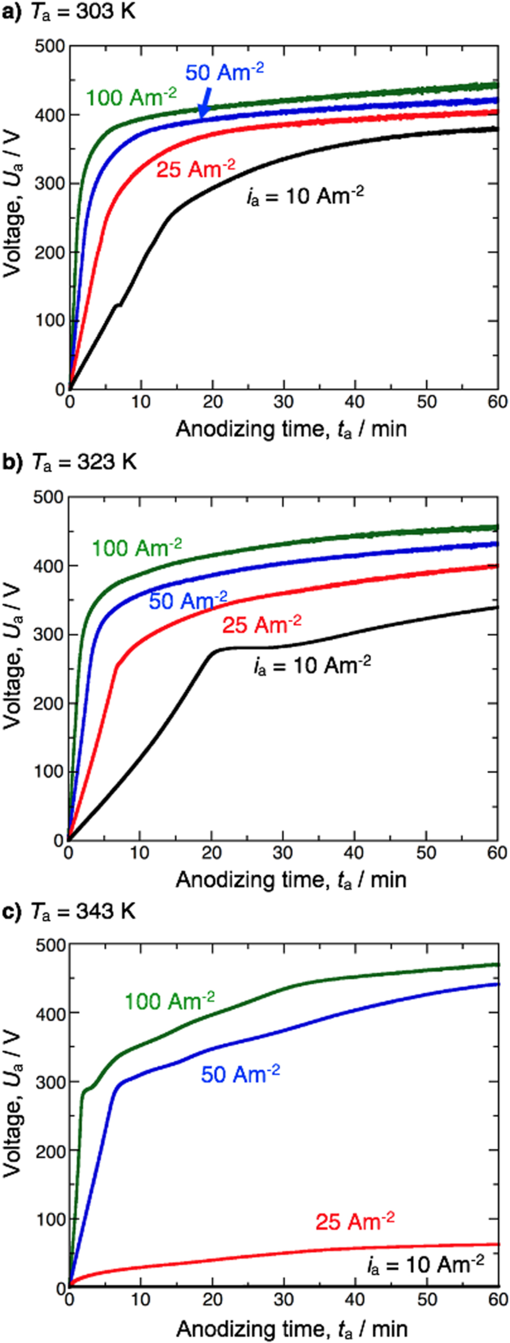
We first examined the formation behavior of the anodic oxide during galvanostatic anodizing of Al in ammonium tetraborate under different operating conditions. Figure 1a shows the time variations of the voltage after anodizing at current densities of 10–100 Am−2 in a 0.3 M ammonium tetraborate solution at 303 K. At the lowest current density of 10 Am−2, the voltage increased linearly with the anodizing time initially because of the formation of anodic oxide on the Al anode. Many visible sparks were observed on the Al anode at a voltage greater than approximately 270 V, and the rate of increase of the voltage gradually slowed with increasing anodizing time. Finally, the voltage reached an almost steady value, measuring approximately 375 V after anodizing for 60 min. The slope of the V–t curve in the initial voltage increase region increased with the increase in current density, and the voltage measured after 60 min also increased with the increase in current density. The highest voltage of 445 V was measured by anodizing at 100 Am−2 for 60 min. The overall shape of the voltage-time curves obtained at higher temperatures of 323 K (Fig. 1b) and 343 K (Fig. 1c) were relatively similar to those obtained at 303 K. However, in the case of 343 K, the slopes of 25 Am−2 and 10 Am−2 are remarkably lowered compared to the lower temperature cases. As expected, a thinner oxide film was formed or active dissolution of the Al substrate occurred at the high temperature of 343 K and these low current densities due to the high solubility of the ammonium tetraborate solution. The structural characterization of the typical anodic oxide formed by anodizing at 323 K was performed in detail using SEM techniques.

Figure 1. Time variations of the voltage during galvanostatic anodizing of Al at 10–100 Am−2 in a 0.3 M ammonium tetraborate solution at (a) 303 K, (b) 323 K, and (c) 343 K.
Download figure:
Standard image High-resolution imageFigure 2 shows SEM images of the surface (upper) and cross-section (lower) of the anodic oxide obtained by anodizing in a 0.3 M ammonium tetraborate solution at 323 K and 100 Am−2, and Figs. 2a–2d correspond to anodizing times of 1 min, 2 min, 5 min, and 60 min, respectively. The voltage increased linearly with increasing anodizing time, reaching approximately 170 V at the time of anodizing for 1 min (Fig. 1b). At this voltage, a flat smooth barrier oxide film was observed on the Al surface (Fig. 2a). However, the corresponding high-magnification cross-sectional image shows that linear ridges measuring several hundred nanometers in width were partially formed on the barrier oxide film. Although no visible sparking was observed at this stage, an invisible breakdown of the barrier oxide film might have gradually started. As the anodizing time was increased to 2 min, the voltage reached to approximately 295 V (Fig. 1b), and many visible sparks were observed from the Al plate due to plasma generation. Accordingly, some areas of the Al surface were covered with submicron- and micron-scale bumpy oxides possessing a molten oxide-like smooth morphology owing to oxide melting, which was caused by sparking and subsequent rapid solidification (Fig. 2b). Although the interface between the oxide layer and Al substrate was uneven because of sparking, there was a thicker barrier layer compared to the short anodizing time (1 min). As the voltage increased to 360 V by further increasing the anodizing time to 5 min (Fig. 1b), the roughness of the textured oxide film increased (Fig. 2c). Finally, as the anodizing time increased to 60 min and the voltage increased to 450 V (Fig. 1b), the Al surface was covered with an extremely uneven oxide layer possessing numerous pores of various sizes, from large to small, and many cracks around the large pores. Such a highly uneven surface morphology was very similar to the typical PEO film previously reported. 42–46

Figure 2. Surface and cross-sectional morphologies of the anodic oxide obtained by anodizing in a 0.3 M ammonium tetraborate solution at 323 K and 100 Am−2 for different times of (a) 1 min, (b) 2 min, (c) 5 min, and (d) 60 min.
Download figure:
Standard image High-resolution imageFigure 3 shows XRD patterns of (a) electropolished Al and (b) anodic oxide obtained by anodizing at 100 Am−2 for 60 min. Three typical diffraction peaks of the Al substrate were measured from the electropolished specimen (Fig. 3a). In addition to these metallic Al peaks, crystalline α-alumina and γ-alumina peaks and a broad peak corresponding to amorphous alumina were measured from the anodized specimen (Fig. 3b). Because the barrier and porous oxide films obtained by anodizing Al without plasma sparking consisted of completely amorphous Al oxide, these crystalline oxides were formed by rapid heating and cooling of the amorphous alumina due to plasma sparking while anodizing at high voltages. To understand the nanostructure of the PEO film in more detail, the anodized specimens were examined by high-magnification STEM.

Figure 3. XRD patterns of the Al specimen after (a) electropolishing and (b) subsequent anodizing in a 0.3 M ammonium tetraborate solution at 323 K and 100 Am−2 for 60 min to form a plasma electrolytic oxidation (PEO) film.
Download figure:
Standard image High-resolution imageFigure 4a shows a bright-field (BF) STEM image of the anodic oxide formed by anodizing in a 0.3 M ammonium tetraborate solution at 323 K and 10 Am−2 for 60 min. As observed in the SEM images shown in Fig. 2, the anodic oxide possessed a two-layer structure consisting of a thin inner oxide layer and a thick outer porous layer. The contrast of the BF-STEM image of the inner layer was uniform, whereas that of the outer layer was non-uniform. A transmission electron microscopy (TEM) image of a different position of the same specimen and the corresponding two high-resolution images of the inner and outer layers are shown in Fig. 4b. The inner oxide layer consisted of uniform amorphous alumina measuring approximately 200 nm in thickness with a halo pattern, and this layer was very similar to the typical barrier oxide film formed by anodizing in neutral solutions. In contrast, the outer oxide layer consisted of amorphous alumina and fine crystalline alumina. Therefore, anodizing Al in an ammonium tetraborate solution enabled the formation of a PEO film consisting of an inner amorphous barrier oxide film and an outer amorphous/crystalline porous oxide.

Figure 4. (a) BF-STEM image of the anodic oxide formed by anodizing in a 0.3 M ammonium tetraborate solution at 323 K and 10 Am−2 for 60 min (b) A TEM image and the corresponding high-magnification TEM images of the anodic oxide formed at the same anodizing conditions. The insert figures show a selected area diffraction pattern of the inner and outer oxide layers.
Download figure:
Standard image High-resolution imageThe barrier oxide film formed on the Al substrate while anodizing Al in neutral solutions without breakdown had a uniform, flat morphology. In contrast, the morphology of the inner barrier layer formed by anodizing in an ammonium tetraborate solution with visible sparks was wavy, as shown in Fig. 2. Therefore, the formation behavior of this PEO film is described as follows: (a) A uniform amorphous barrier oxide film was formed on the Al substrate in the early stage of anodizing, and the thickness of the barrier film increased with increasing anodizing time and voltage. (b) As the voltage reached the threshold value for oxide breakdown, the barrier film was locally broken by plasma sparking, and the anodic oxide around the sparking points rapidly melts and then rapidly solidifies. In addition, the aluminum substrate also melted, evaporates, and then solidified. 54 Simultaneously, an amorphous barrier layer was immediately formed at the sparking points. (c) The outer crystalline porous layer was thickened by continuous rapid melting and solidification at the bottom barrier layer and the aluminum substrate by plasma sparking. (d) After numerous plasma sparks occurred on the anodic oxide after a longer anodizing time, a PEO film consisting of a thick outer amorphous/crystalline porous oxide layer and an inner amorphous barrier oxide layer was obtained on the Al surface.
Figure 5 shows SEM images of the PEO film formed by anodizing at 100 Am−2 for 60 min at (a) a low temperature of 303 K and (b) a high temperature of 343 K. Although the amount of the larger microscale pores slightly decreased as the temperature increased, typical uneven PEO films containing various sizes of pores were observed at both temperatures. The formation behavior of this uneven PEO film was unchanged even when the Al specimens were anodized at various current densities and temperatures. In contrast, we found that the surface morphology of the PEO film was drastically changed by anodizing in ammonium tetraborate solutions with different concentrations.

Figure 5. SEM images of the surface anodized in a 0.3 M ammonium tetraborate solution for 60 min at 100 Am−2 and different temperatures of (a) 303 K and (b) 343 K.
Download figure:
Standard image High-resolution imageFigure 6 shows the time variations of the voltage during galvanostatic anodizing in 0.3–2.4 M ammonium tetraborate solutions at 343 K and 100 Am−2. The voltage at which visible plasma sparks occurred decreased with increasing concentration of the ammonium tetraborate solution, from approximately 280 V in 0.3 M to 200 V in 2.4 M. Accordingly, the inflection point of the voltage decreased with increasing concentration, although the voltage gradually increased with increasing anodizing time. There was no significant change in the shape of the voltage-time curves that consisted of a linear increase initially and a subsequent gradual increase, as shown in Figs. 1 and 6. The SEM images of the Al specimens that were anodized in (a) 0.9 M and (b) 2.4 M ammonium tetraborate solutions at 343 K and 100 Am−2 for 60 min are shown in Fig. 7. In contrast to the typical PEO film obtained at a lower solution concentration (Figs. 2 and 5), a relatively uniform porous PEO film with a maze-like structure was obtained in a 0.9 M ammonium tetraborate solution (Fig. 7a). As shown in the high-magnification SEM images, the microscale pores in the anodic oxide possessed a three-dimensional interconnected network structure that had different morphologies than the typical porous alumina with hexagonal alumina walls. A similar uniform porous PEO film was formed on the surface as the concentration further increased to 2.4 M (Fig. 7b), although the pores became smaller and several small grooves were formed; thus, the uniformity of the pore distribution was slightly decreased. The differences in the microstructure of the PEO films shown in Figs. 2 and 7 depend on the plasma generation behavior on the Al surface while anodizing. Therefore, the Al specimens were observed in situ using a digital video camera in ammonium tetraborate solutions with different concentrations.

Figure 6. Time variations of the voltage during galvanostatic anodizing of Al at 100 Am−2 in 0.3–2.4 M ammonium tetraborate solutions at 343 K.
Download figure:
Standard image High-resolution image
Figure 7. SEM images of the Al specimen in (a) 0.9 M and (b) 2.4 M ammonium tetraborate solutions at 343 K and 100 Am−2 for 60 min. The bottom figures show the high-magnification SEM images of (a) the surface and (b) the cross-section of the specimen anodized at 0.9 M.
Download figure:
Standard image High-resolution imageFigure 8 shows video snapshots of the surface appearance of the Al anode at 60 min after the specimen was anodized in (a) 0.3 M, (b) 0.9 M, and (c) 2.4 M ammonium tetraborate solutions at 343 K and 100 Am−2. At the low concentration of 0.3 M (Fig. 8a), non-uniform plasma sparks with different sizes were observed on the Al anode, and less plasma sparking was observed. In contrast, numerous small plasma sparks were uniformly observed on the whole Al surface as the concentration increased to 0.9 M (Fig. 8b). Small plasma sparks were also observed during anodizing in a 2.4 M ammonium tetraborate solution, whereas the sparking region was non-uniform compared to that of 0.9 M. However, this sparking region moved with the anodizing time, and consequently a uniform PEO film was formed on the surface. Namely, the plasma generation behavior strongly depended on the concentration of the ammonium tetraborate solution; consequently, the surface morphology of the obtained PEO film was also greatly affected. The SEM images of the surfaces of the resulting PEO films that are shown in Figs. 2 and 7 reflected these contrasting non-uniform and uniform plasma generation behaviors.

Figure 8. Video snapshots of the surface appearance of the Al anode at 60 min after the specimen was anodized in (a) 0.3 M, (b) 0.9 M, and (c) 2.4 M ammonium tetraborate solutions at 343 K and 100 Am−2.
Download figure:
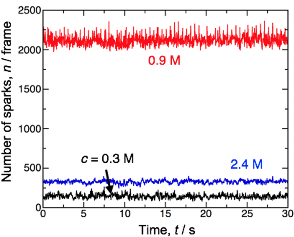
Standard image High-resolution imageFigure 9 summarizes the time variation of the number of plasma sparks per frame (30 fps) measured by in situ observations using a digital video camera, n, in different electrolyte concentrations of 0.3–2.4 M at 343 K and 100 Am−2. Here, the in situ observations and subsequent plasma spark measurements were carried out 60 min after the specimen was anodized for 30 s. The average spark number was approximately 150 frame−1 at a low concentration (0.3 M), although the number of plasma sparks had a slight oscillation in the range of 100–200 frame−1 while anodizing. In contrast, a 10 times larger average spark number was measured when the oscillation was in the range of 2000–2300 frame−1 while anodizing at the higher concentration of 0.9 M. However, the average spark number decreased to approximately 330 frame−1 as the electrolyte concentration further increased to 2.4 M. Therefore, anodizing Al using an ammonium tetraborate solution with an intermediate concentration of 0.9 M, which was more than the saturated solubility at room temperature, increased the number of plasma sparks, homogenization of the plasma distribution, and formation of a relatively uniform porous PEO film. This behavior may be due to the transition of soft sparking. It has been reported that the soft sparking technique causes the formation of compact PEO film with good wear performance, and the soft sparking mode is achieved under low voltage conditions. 55,56 Because the voltage decreased with increasing concentration (Fig. 6), the soft sparking mode may occur at higher concentrations.

Figure 9. Changes in the number of plasma sparks per frame measured by in situ observations using a digital video camera, n, as functions of the time, t, at different ammonium tetraborate concentrations of 0.3–2.4 M at 343 K and 100 Am−2. The measurements were carried out 60 min after the specimen was anodized for 30 s.
Download figure:
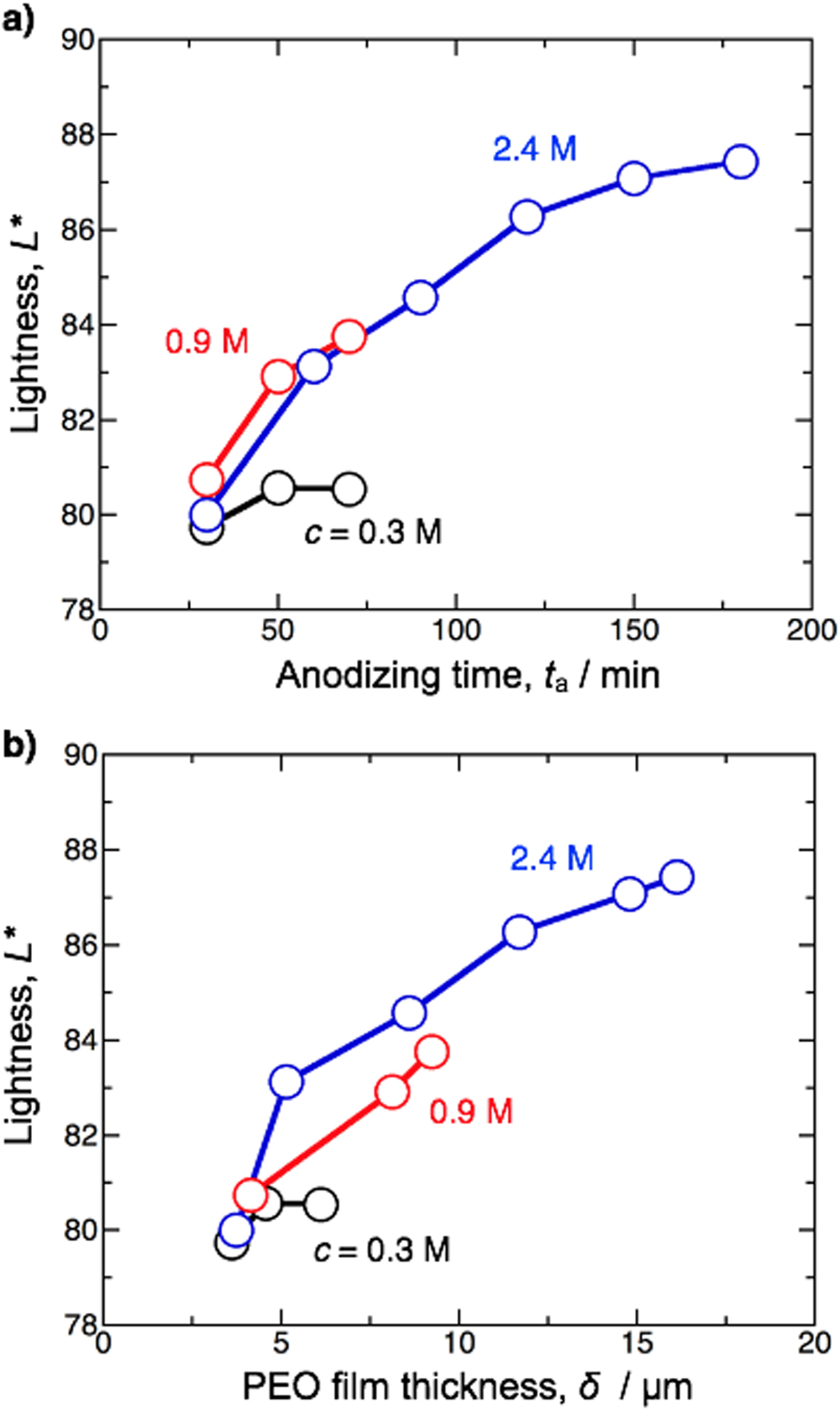
Standard image High-resolution imageThe PEO films formed by anodizing in ammonium tetraborate exhibited a bright white hue. Figure 10a shows the changes in the lightness of the Al surface covered with the PEO film, L*, as functions of time by anodizing in 0.3–2.4 M ammonium tetraborate solutions at 343 K and 100 Am−2. The lightness value of the specimen obtained in a 0.3 M ammonium tetraborate solution was approximately 80 and almost unchanged with increasing anodizing time. In contrast, the lightness obtained at higher concentrations (0.9 M and 2.4 M) gradually increased with increasing anodizing time. At the low concentrations of 0.3 M and 0.9 M, long-term anodizing processes that were more than 90 min resulted in the partially active dissolution of the Al substrate by the localized concentration of current due to higher voltages; thus, long anodizing times could not be performed at these lower concentrations. In contrast, a uniform PEO coating without active dissolution was achieved by long-term anodizing for more than 90 min at a higher concentration of 2.4 M ammonium tetraborate, and the lightness of the Al surface increased gradually with increasing anodizing time, although the increasing rate of lightness decreased with increasing time. Therefore, a bright white PEO film with a high lightness value of 87.5 was obtained by anodizing for 180 min. The relationship between the lightness and thickness of the PEO film, δ, is summarized in Fig. 9b. The lightness of the PEO film increased with increasing PEO film thickness, which was almost independent of the non-uniformity and uniformity of the pore structures in the PEO film. Therefore, the thick PEO coating enabled the formation of a bright white Al surface. This white hue may be due to the light scattering from the PEO film containing many nanoscale α-alumina and γ-alumina particles in the amorphous alumina matrix.

Figure 10. Changes in the lightness of the PEO film, L*, formed in 0.3–2.4 M ammonium tetraborate solutions at 343 K and 100 Am−2 as functions of (a) the anodizing time, ta, and (b) the thickness of the PEO film, δ.
Download figure:
Standard image High-resolution imageWe investigated whether a similar bright white PEO film could be formed on typical industrial Al alloys. Figure 11a shows the time variations of the voltage during galvanostatic anodizing of A1050, A5052, A6061, A7075, and ADC12 Al alloys in a 0.9 M ammonium tetraborate solution at 343 K and 100 Am−2 for 60 min. The shapes of the voltage-time curves measured using A1050, A5052, A6061, and A7075 alloys, which consisted of linear and gradual voltage increases, were very similar to that obtained using the high-purity Al plate shown in Fig. 6, although the voltage was slightly lower overall owing to the addition of the alloying elements. Consequently, bright white PEO films with a uniform maze-like structure were successfully formed on these Al alloys (Fig. 11b). However, the voltage remained constant at approximately 25 V during galvanostatic anodizing of the ADC12 Al alloy, and no plasma spark occurred on the surface when anodizing this specimen. Therefore, a non-uniform dark gray surface with several imperfections was obtained. Thus, a higher voltage of approximately more than 250 V was required for the occurrence of plasma sparks and the subsequent formation of a uniform PEO film. The ADC12 Al alloy contains Al-Si and Al-Fe-Mn-Si intermetallic compounds in the matrix. As the ADC12 Al alloy was anodized in ammonium tetraborate, oxygen gas evolution occurs on these Al-Si and Al-Fe-Mn-Si phases. Therefore, the voltage is low comparing to the cases of other Al alloys.

Figure 11. Time variations of the voltage during galvanostatic anodizing of A1050, A5052, A6061, A7075, and ADC12 alloys at 100 Am−2 in 0.9 M ammonium tetraborate solutions at 343 K, and the corresponding appearances and SEM images of the surfaces of these Al alloys anodized for 60 min.
Download figure:
Standard image High-resolution imageThe water wettability of the maze-patterned PEO film formed by galvanostatic anodizing of high-purity Al in a 0.9 M ammonium tetraborate solution at 323 K and 100 Am−2 for 60 min was investigated by static contact angle measurements. Figure 12a shows the appearance of a water droplet on the PEO film. Because the Al surface was completely covered with hydrophilic porous aluminum oxide, the anodized specimen exhibited a weak hydrophilicity and had an average static contact angle of 21.7°. This value was slightly higher than that of typical porous aluminum oxide films formed by anodizing in acidic solutions that measure approximately 10°. 57 This hydrophilic PEO specimen was immersed in a HDFOPA ethanol solution to form a SAM coating, and the obtained hydrophobic PEO film was investigated by dynamic contact angle measurements (Fig. 12b). The SAM-coated PEO film exhibited a higher average advancing contact angle of 154.1°, and a superhydrophobic PEO film was easily obtained by surface modification with a SAM, whereas a weak slipping behavior occurred on the surface, measuring 74.9° according to the average receding contact angle and 79.2° according to the contact angle hysteresis.

Figure 12. Appearances of water droplets on (a) the PEO film formed by galvanostatic anodizing of high-purity Al at 100 Am−2 in 0.9 M ammonium tetraborate solutions at 323 K for 60 min during a static contact angle measurement and (b) the HDFOPA-SAM-coated PEO film during a dynamic contact angle measurement.
Download figure:
Standard image High-resolution image
Conclusions
High-purity Al plates were anodized in 0.3–2.4 M ammonium tetraborate solutions at 303–343 K under various electrochemical conditions, and the resulting anodic oxide films were investigated by SEM, STEM, XRD, spectrophotometry, and contact angle measurements. A thin barrier oxide film was formed in the early stage of anodizing, and numerous visible plasma sparks occurred after the voltage reached the breakdown voltage. Consequently, a PEO film with a two-layer structure consisting of an outer porous layer consisting of amorphous alumina and crystalline alumina with α- and γ-phases and an inner amorphous barrier alumina layer was formed on the Al surface. An uneven PEO film containing various sizes of pores and a large undulation was formed in a 0.3 M ammonium tetraborate solution, whereas a maze-like patterned PEO film with similar pore sizes and a relatively smooth surface was obtained at a higher concentration of 0.9–2.0 M ammonium tetraborate. This difference in the PEO film morphology was due to the plasma generation behavior while anodizing. The lightness of the PEO film increased with increasing anodizing time and PEO film thickness, and a bright white PEO film measuring 87.5 in lightness was formed by long-term anodizing. The obtained PEO film exhibited weak hydrophilicity according to a contact angle measurement of 21.7°, and a superhydrophobic PEO film that had a contact angle of 154.1° was easily fabricated by SAM modification. Similar bright white PEO films were formed on various industrial Al alloys, including A1050, A5052, A6061, and A7075.
Acknowledgments
The SEM and STEM observations in the present investigation were financially supported by the Nanotechnology Platform Program at Hokkaido University (A-19-HK-0034 and A-20-HK-0037). We wish to thank Dr. Takashi Endo and Mr. Ryo Oota for their technical support in these observations.