
Abstract
Chemical redox reactions between redox shuttles and lithium-ion battery particles have applications in electrochemical systems including redox-mediated flow batteries, photo-assisted lithium-ion batteries, and lithium-ion battery overcharge protection. These previous studies, combined with interest in chemical redox of battery materials in general, has resulted in previous reports of the chemical oxidation and/or reduction of solid lithium-ion materials. However, in many of these reports, a single redox shuttle is the focus and/or the experimental conditions are relatively limited. Herein, a study of chemical redox for a series of redox shuttles reacted with a lithium-ion battery cathode material will be reported. Both oxidation and reduction of the solid material with redox shuttles as a function of time will be probed using ferrocene derivatives with different half-wave potentials. The progression of the chemical redox was tracked by using electrochemical analysis of the redox shuttles in a custom electrochemical cell, and rate constants for chemical redox were extracted from using two different models. This study provides evidence that redox shuttle-particle interactions play a role in the overall reaction rate, and more broadly support that this experimental method dependent on electrochemical analysis can be applied for comparison of redox shuttles reacting with solid electroactive materials.
Export citation and abstract BibTeX RIS
Chemical redox between solid lithium (Li)-ion battery active materials and dissolved redox active species (i.e., redox shuttles) has relevance in several electrochemical systems and applications including battery overcharge protection, 1–4 redox-mediated flow batteries, 5–9 and photo-assisted rechargeable Li-ion batteries. 10,11 The chemical redox process involves charge transfer between solid electroactive particles and soluble redox shuttles within an electrolyte. While the choice of solid active material to be used in a Li-ion battery is a thoroughly researched and constantly evolving field, the selection principles and properties for redox shuttles for the multiple applications mentioned above have not been as comprehensively investigated and reported. This study aims to achieve progress towards methods to rationally compare the properties of several redox shuttles desired for pairing for redox reactions with a target solid electroactive material.
In addition to measuring relative properties of the redox shuttles, in particular reaction rates under equivalent conditions, systematic study of several redox shuttles is expected to give insights into the interactions between the redox shuttles and the solid electroactive materials. 12–15 It was previously proposed that the process for redox reactions between redox shuttles and solid active materials proceeds through a multistep process where the shuttle diffuses to the surface of the solid particles, adsorbs, undergoes electron transfer, and desorbs. 12 The structure and composition of the redox shuttle, and interactions between the redox shuttle and solid electroactive material, would be expected to influence the overall redox reaction rate. The specific limiting process in the overall reaction will influence the extent to which different interactions impact the overall redox reaction rate. To the authors' knowledge, detailed understanding of how redox shuttle properties and composition, including chemical functional moieties and the electrochemical potentials of the redox shuttles, impact rates of chemical redox with battery active materials has not been reported. A detailed model and understanding of the chemical redox reaction is outside of the scope of this manuscript, however, this initial study will report an experimental system for assessing the reaction rate of different redox shuttles with solid electroactive materials. This work will also provide insights into challenges in making these measurements and how different chemical modifications to the redox shuttles influenced the redox reaction rate.
The solid electroactive material chosen for this study was the cathode material LiFePO4 (LFP), as well as its oxidized and delithiated form FePO4 (FP). 16 Chemical oxidation/delithiation of LFP, and reduction/lithiation of FP, is represented by Eqs. 1 and 2, respectively.


where RSox is a redox shuttle used for the oxidation of LFP and RSred is a redox shuttle used for the reduction of FP. The redox shuttles used in this manuscript have a net charge of either neutral or +1, however, other charge states for redox shuttles are possible. 15,17 To be thermodynamically favorable, the redox potential of RSox must be higher than LFP whereas, the redox potential of RSred must be lower than that of FP. LFP has been previously studied for both chemical and electrochemical redox, and electrochemical oxidation/reduction of this material occurs at a relatively flat potential as a function of extent of lithiation near 3.45 V vs Li/Li+. 18,19 LFP thus has two attributes that make it well suited to chemical redox investigations: i) a relatively constant potential for oxidation or reduction, meaning that any potential difference and effective thermodynamic driving force will be dictated by the redox shuttle chemistry and conditions for a wide range of extents of lithiation of the solid electroactive material and, ii) there is a wide range of oxidizing potentials available for appropriate redox shuttles that will still be within the thermodynamic stability window of common Li-ion battery electrolytes. 20
Systematic studies of redox shuttles for overcharge protection in Li-ion batteries has been done using metallocenes, 21 aromatics 22,23 and, halogenated Li salts. 24,25 The focus in these studies was generally the overall stability and lifetime of the redox shuttle when electrochemically oxidized and reduced repeatedly in Li-ion cells. While intended for overcharge protection of cathodes, these shuttles can also be used for chemical oxidation in redox-targeting systems. 11,26 Kinetics of chemical redox have previously been reported with ferrocene-based molecules, 5,13,27 hydrogen peroxide, 28 lithium iodide 29 and, electrolyte-free compounds such as NO2. 30 There has been a lack of understanding in the role of redox shuttle properties on the chemical redox rate and mechanism. For instance, Yu et al. recently reported that ferricyanide, despite having similar redox potential to dibromoferrocenium, has 1000 times faster delithiation kinetics when used to chemically oxidize LFP. 5 It is noted that the electrolytes used for the two redox shuttles were different, hence redox shuttle-electrolyte interactions might also play a role in the observed differences in reaction rate. In the study herein, the reaction rate for the oxidation/reduction of LFP/FP by six redox shuttles (three for oxidation of LFP and three for reduction of FP) are compared using electrochemical analysis to track the progression of the chemical redox reactions. The reaction rate is discussed in the context of the redox potential of the redox shuttles and their measured effective diffusion coefficients. The reactions were performed in a batch reactor system and the progression of the reaction was monitored in situ using electrochemical analytical techniques. Two first-order reaction models were used to quantify rate constants and LFP/FP phase transformation.
Experimental
Materials
Ferrocene (Fc), 1,1' dimethylferrocene (DMFc), ethylferrocene (EFc), 1,1' dibromoferrocene (DBFc), ferrocene carboxaldehyde (FcCX), and 1,1' diacetylferrocene (DAFc) were used as received from Sigma Aldrich without any further purification. The chemical structure of these species, which were used as the redox shuttles in this study, can be found in Table I. 1.2 M LiPF6 in 3:7 ethylene carbonate:ethyl methyl carbonate (wt.%:wt.%) was used as electrolyte in all experiments (Gotion Inc.). Commercial LFP (Xiamen TOB New Energy Technology, China) was used as received. The surface area of the LFP used was 7.5 m2 g−1, measured using the Brunauer–Emmett–Teller method (Quantachrome Instruments). Note that the LFP did not undergo a carbon coating step during production according to the manufacturer specification. Material and electrochemical properties for the LFP material have been detailed in previous publications. 31,32
Table I. The redox shuttles for reduction of FP (DMFc, EFc and, Fc) and oxidation of LFP (FcCX+, DBFc+ and, DAFc+). The half-wave potential and effective diffusion coefficient was measured in 100 mM solution of redox shuttle in 1.2 M LiPF6 in 3:7 wt.% EC:EMC using cyclic voltammetry. The standard error is from measuring Deff in three independent experiments.
| Redox Shuttle | Chemical Structure | Half-Wave Potential (V vs Li/Li+ ) | Diffusion Coefficient, Deff (cm2 s−1) |
|---|---|---|---|
| 1,1'-Dimethylferrocene (DMFc) |

| 3.10 | (2.20 ± 0.27) × 10−6 |
| Ethylferrocene (EFc) |

| 3.17 | (3.34 ± 0.82) × 10−6 |
| Ferrocene (Fc) |

| 3.25 | (1.92 ± 0.56) × 10−6 |
| Ferrocenium carboxaldehyde (FcCX+) |

| 3.55 | (8.15 ± 1.25) × 10−7 |
| 1,1'-Dibromoferrocenium (DBFc+) |

| 3.57 | (9.81 ± 6.03) × 10−7 |
| 1,1'-Diacetylferrocenium (DAFc+) |
| 3.76 | (1.28 ± 0.44) × 10−8 |
FePO4 preparation
For experiments where FePO4 (FP, which was oxidized and delithiated LFP) was used, the FP was produced from a chemical oxidation process. 5 g LFP was added to a 750 ml solution containing 25 ml hydrogen peroxide (30% in water), 25 ml glacial acetic acid, and deionized (DI) water. 29 The solution was kept unstirred for 1 h, and then filtered to extract the solid product. The solid product was then dried at 80 °C for 8 h in a convection oven and then for 4 h under vacuum. Conversion of LFP into FP was confirmed using powder X-ray diffraction (XRD, Panalytical X'pert diffractometer). After the chemical oxidation procedure the XRD patterns were consistent with previous reports for FP (see Supplementary Material, Fig. S1 available online at stacks.iop.org/JES/168/050546/mmedia). 29 The solution was intentionally unstirred during LFP oxidation to FP in order to prevent the degradation of LFP surface induced by mechanical agitation. 31 Electrochemical evaluation of electrodes containing the FP confirmed the chemical oxidation process was reversible, although there was a small reduction in electrochemical capacity and rate capability (see Supplementary Material, Figs. S2 and S3).
Electrochemical characterization
The prepared FP and original LFP were electrochemically evaluated as cathode active materials using 2032-type coin cells on a MACCOR battery cycler. The cathodes were fabricated using a slurry of 80:10:10 (by wt. %) active material: carbon black: polyvinylidene difluoride (PVDF, Sigma Aldrich), where the active material was LFP or FP. The components were blended into a slurry using N-methyl-2-pyrrolidene as added solvent, and the slurry was cast on an aluminum current collector using a doctor blade with a 125-μm gap. The electrodes were dried overnight in an ambient oven at 80 °C, followed by a vacuum oven for another 2 h at 80 °C. The thickness of the electrodes used in this study was measured using a digital micrometer to be 70 ± 5 μm and LFP/FP loading was 6.2 ± 0.3 mg cm−2, where the error is the standard deviation of 3 independent measurements. The LFP/FP electrodes were used as cathodes and were paired with Li foil as the anode. Celgard 2325 was used as the separator and the electrolyte was 1.2 M LiPF6 in 3:7 vol % ethylene carbonate: ethyl methyl carbonate. The cells were cycled at room temperature with the same rate used for both charge and discharge for each cycle with the following cycling profile: C/20 (three cycles), C/10 (two cycles), C/5 (two cycles), C/2 (two cycles), 1C (two cycles), and C/20 (two cycles). The C rate was determined based on the mass of LFP/FP in the cell, where 1C was assumed to correspond to 160 mA g−1 LFP/FP. Representative rate capability results can be found in Supplementary Material, Figs. S2 and S3 for LFP and FP, respectively. Note that the Li/LFP cells were started with a charge cycle and Li/FP cells were started with a discharge cycle. The voltage window for all electrochemical measurements was 2.5 to 4 V (vs Li/Li+).
Bulk electrolysis of redox shuttles
All experiments with redox shuttles were conducted within an argon-filled glove box (H2O < 1 ppm, O2 < 1 ppm). For the FcCX, DBFc, and DAFc redox shuttles, it was desired to have them in the oxidized form such that they could be used to chemically oxidize LFP, thus the redox shuttles were converted to the oxidized form using bulk electrolysis. 100 mM solutions of FcCX, DBFc, and DAFc were oxidized at a constant voltage of 4.2 V (vs Li/Li+) using platinum wire (Sigma Aldrich) as working electrode and Li foil as counter and reference electrode in an H-cell (Ace Glass). The solutions were oxidized at 4.2 V (vs Li/Li+) until a current cutoff of 10−6 Amps. An image of the cell setup can be found in Supplementary Material, Fig. S4. The ion selective polymer separator that was between the two compartments of the H-cell was a blend of Nafion and PVDF, and the preparation of the separator has been described previously. 33,34 All electrochemical measurements using the H-cell were conducted using Biologic-50 or Biologic-150 potentiostats.
Half-wave potential determination
To determine half-wave potentials for the redox shuttles, cyclic voltammetry (CV) on 100 mM solutions containing redox shuttles (DMFc, Fc, EFc, DBFc, FcCX, and DAFc) were conducted after electrolysis of the solutions to a capacity consistent with 50% oxidation (e.g. a 50/50 mix of the redox shuttle in the oxidized and reduced form). The CV experiments were conducted using a 1.6 mm Pt disc (BASi) working electrode and Li metal combined reference and counter electrode with a sweep rate of 100 mV s−1 in the H-cell. The H-cell setup was similar to the bulk electrolysis experiment explained above (Fig. S4).
Characterization of chemical redox reaction rate dependence on relative redox shuttle to solid active material ratio
Monitoring of the progress of chemical oxidation of LFP with DBFc+, and chemical reduction of FP by Fc, was measured in a three neck round bottom flask (Grainger) using Pt disc as working electrode, 100 mM Ag/AgNO3 in 1.2 M LiPF6 in 3:7 vol % ethylene carbonate:ethyl methyl carbonate electrolyte as reference electrode, and Pt wire as counter electrode (for a picture of the experimental setup, see Supplementary Material, Fig. S5). For oxidation of LFP with DBFc+, 100 mM solution of oxidized DBFc (e.g. >97% DBFc+ as determined by mAh of capacity passed during electrolysis) dissolved in the 1.2 M LiPF6 in 3:7 vol % ethylene carbonate:ethyl methyl carbonate electrolyte was added to a round bottom glass. Mild stirring at 130 rpm was added to the solution to prevent sedimentation of the solid electroactive material particles. Reference cyclic voltammograms at 20, 40, 50, 60, 80 and, 100 mV s−1 were performed. Three case studies were evaluated by varying the molar ratio of LFP to DBFc+: particle-lean (1:2), equimolar (1:1), and particle-rich (2:1). Similar experiments were performed for the redox reaction of the reduction of FP using Fc by varying the amounts of FP added to 100 mM Fc electrolyte solution. Three independent experiments were performed for each reaction condition (LFP with DBFc+ and FP with Fc) at the three different molar ratios of solid electroactive species to redox shuttle.
Comparing redox shuttles
Chemical oxidation of LFP using FcCX+ and DAFc+ and reduction of FP using DMFc and EFc were performed in the particle-rich scenario (2:1 LFP or FP: redox shuttle concentration). The concentration used for each redox shuttle was 100 mM. The experimental setup was similar to the experiments mentioned above (Fig. S5). Three independent measurements with each redox shuttle were performed with 200 mM of LFP/FP powder.
Results
The class of metallocene organic redox shuttles have been used for chemical redox of Li-ion battery solid active materials in previous reports. 6,33 Besides chemical redox of solid electroactive materials, metallocene-based redox flow batteries have also been reported. 35,36 Criteria for their selection has included ease of availability, solubility, electrolyte stability, and molecular tunability. 36 Metallocenes have two cyclopentadienyl anions (C5H5 −) bound to a transition metal ion, thus forming a (C5H5)2M compound (where M is a metal, e.g., Fe). The cyclopentadienyl rings may be substituted with different chemical functional groups, thus making the properties of a given metallocene highly tunable. Ferrocenes are one such group of metallocenes and have been used as redox shuttles, including towards energy storage applications. 6,33,36
This study focuses on how properties of redox shuttles affect the rate of chemical redox of a solid Li-ion electroactive material. Commercially available derivatives of ferrocene have been evaluated herein, all having solubility of at least 100 mM in the electrolyte and without observed reactions with the electrolyte, at least in the neutral form of the redox shuttle. Based on Eqs. 1 and 2, redox shuttles with a redox potential above 3.45 V vs Li/Li+ were studied for oxidation of LFP, whereas shuttles with half-wave potential lower than 3.45 V vs Li/Li+ were used for reduction of FP. Cyclic voltammograms of the shuttles with respect to Li/Li+ can be found in Supplementary Material, Fig. S6. Three oxidizing shuttles (FcCX+, DBFc+, and DAFc+) and three reducing shuttles (Fc, EFc, and DMFc) were selected. It is noted here that an additional redox shuttle, Decamethylferrocene, was evaluated but could not be included in the study due to solubility limitations in the electrolyte, and what appeared to be the facilitation of formation of a passivation layer on the Pt disc working electrode. 37
To design the experimental system for comparison between redox shuttles, first the impact of relative molar concentration of redox shuttles to solid electroactive particles was investigated. Three scenarios were considered: particle-rich, equimolar, and particle lean. The redox shuttle concentration was kept constant at 100 mM, and the solid electroactive material concentration was varied at 200 mM (particle-rich), 100 mM (equimolar), and 50 mM (particle-lean). Fc and DBFc+ were used as reducing and oxidizing redox shuttles, respectively, because this pair of shuttles has been previously reported for reversible chemical redox of LFP/FP. 6 The progress of the reaction was evaluated using a three-electrode configuration within a batch reactor system. After the addition of powder to the batch reactor, cyclic voltammograms where collected continuously at a sweep rate of 100 mV s−1 using a Pt disc electrode. The reaction between LFP and DBFc+ and FP and Fc proceeded according to Eqs. 1 and 2, respectively. The Randles-Sevcik equation was applied to convert measured peak currents to concentrations of the oxidized and/or reduced form of the redox shuttles during the chemical redox reaction progression. 38 Further description of this analysis can be found in the Supplementary Material. Under the assumption that changes in the concentration of the different oxidation states of the redox shuttles were only due to the chemical redox between the redox shuttles and the solid electroactive material, conversion of solid electroactive material was calculated from the electrochemical redox shuttle concentration analysis. The extent of oxidation and thus delithiation of LFP by DBFc+ at three different redox shuttle: particle molar ratios can be found in Fig. 1a, and the corresponding conditions for reduction/lithiation of FP by Fc can be found in Fig. 1b. Effective diffusion coefficient of the redox shuttles in the electrolyte used was also determined by varying sweep rate of CV scans at constant concentration and applying the Randles-Sevcik equation. These results can be found in Table I.
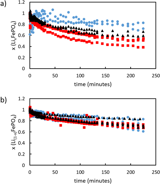
Figure 1. Degree of delithiation/lithiation at different solid powder: redox shuttle molar ratios of particle-rich (2: 1, black triangles), equimolar (1: 1, red squares) and, particle-lean concentrations (1: 2, blue circles) for (a) LFP oxidation using 100 mM FcBr2 + solution and (b) FP reduction using 100 mM Fc solution.
Download figure:
Standard image High-resolution imageOne possible contributor to the measured currents during CV sweeps would be the solid electroactive materials themselves, as has been previously reported for Li-ion battery particle suspensions, 39 although those previous reports were under different shear conditions, suspension compositions, working electrode area and orientation, and/or particle loading. To evaluate the possible contributions of electrochemical current from the particles themselves, a control experiment was conducted with CV scans at 100 mV s−1 between −0.7 − 0.1 V vs 10 mM Ag/AgNO3, where 500 mg LFP powder (e.g. 200 mM particle concentration) was added to the three-electrode batch reactor without redox shuttles present. There were no clear peaks in measured currents during CV sweeps to indicate significant contributions from oxidation/reduction of the solid electroactive particles from encountering the microelectrode probe. The background current was generally <0.1 mA cm−2, which amounts to approximately 1%–2% of the current response from 100 mM redox shuttle solutions (see Supplementary Material, Fig. S7). This result supported neglecting the contributions from solid particle collisions in using peak currents from CV scans to determine the change in concentration of the oxidized/reduced form of the redox shuttles, and neglecting changes in oxidation state or lithiation of the LFP/FP due to electrochemical reactions with the working electrode. It is also noted that at the conclusion of experiments visual inspection of the electrode did not suggest the attachment of LFP/FP particles.
Kinetic parameters for the oxidation of LFP and reduction of FP with redox shuttles were determined using the Johnson Mehl Avrami-Erofeyev-Kolmogorov (JMAEK) equation. 40 The JMAEK equation can be written as:

Where x is conversion, k* is a pseudo first order rate constant, t is time and n is Avrami coefficient. Additional details for applying the JMAEK equation to the systems in this study can be found in the Supplementary Material. Similar analysis has previously been used to characterize batch reactor redox reaction rates between redox shuttles and Li-ion battery electroactive materials. 12,28 It is noted that the JMAEK model used herein assumed first order reaction with respect to solid electroactive material, which would be applicable only during conditions where the redox shuttles were not subject to transport or equilibrium limitations to driving the reaction rate. This condition would not be satisfied for particle-rich or equimolar conditions after extended extents of conversion of the electroactive material. To accommodate this limitation, rate constants were only calculated from analysis of the first 100 min of reaction for all reaction systems investigated. The conversion (e.g., delithiation/oxidation of LFP or lithiation/reduction of FP) at the end of the first 100 min (x), rate constant normalized by surface area of LFP/FP (k*), and Avrami coefficient (n) for the experiments varying solid electroactive material:redox shuttle molar ratios can be found in Table II. The conversion referenced in this work was with respect to solid electroactive material. For delithiation/oxidation of LFP, equimolar conditions resulted in the highest conversion after 100 min of the reaction proceeding, followed by the particle-rich and then the particle-lean cases. In contrast, lithiation/reduction of FP followed the same trajectory for conversion irrespective of particle loading. It is noted that only 50% stoichiometric conversion of solid electroactive material is possible for particle-rich scenario.
Table II. Reaction parameters determined for different molar ratios of solid electroactive material:redox shuttles during chemical reduction of FP with Fc and oxidation of LFP with FcBr2 +. x is the extent of reduction/lithiation of FP or oxidation/delithiation of LFP after the first 100 min of the redox reaction, k* is the pseudo first-order rate constant per surface area electroactive material, and n is the Avrami coefficient from Eq. 3. x was calculated based on total moles of solid electroactive materials. Values are averages with errors representing the standard error of three independent experiments.
| Solid Particle:Redox Shuttle (mol:mol) | FePO4 + Fc + Li + → LiFePO4 + Fc + | LiFePO4 + FcBr2 + → LiFePO4 + FcBr2 + Li + | ||||
|---|---|---|---|---|---|---|
| x | k* × 10−3 (m−2 min−1) | n | x | k* × 10−3 (m−2 min−1) | n | |
| 2: 1 | 0.18 ± 0.03 | 2.18 ± 1.00 | 0.40 ± 0.09 | 0.36 ± 0.05 | 2.92 ± 0.58 | 0.52 ± 0.10 |
| 1: 1 | 0.22 ± 0.01 | 2.95 ± 0.51 | 0.44 ± 0.04 | 0.43 ± 0.04 | 8.35 ± 0.14 | 0.52 ± 0.06 |
| 1: 2 | 0.17 ± 0.03 | 1.64 ± 0.67 | 0.38 ± 0.13 | 0.28 ± 0.07 | 7.57 ± 2.52 | 0.54 ± 0.12 |
After the comparison of the progression of the chemical redox for the LFP/ DBFc+ and the FP/Fc systems using varying molar ratios of solid electroactive material:redox shuttle, the next outcome investigated was how different redox shuttles, all of them functionalized ferrocene derivatives, progressed in their chemical redox reactions with FP or LFP. For the comparison between redox shuttles, the particle-rich reaction condition was selected. The particle-rich ratio for some conditions reached equivalent levels of conversion faster, and avoiding extended reaction durations was desirable to avoid any potential effects of side reactions of the redox shuttles. 41 It is noted that even for the particle-rich condition the reaction progressed slow enough that the time resolution of the analytical methods were appropriate and there was confidence in having enough concentration data points to extract kinetic parameters from fitting the data. For reduction/lithiation of FP, similar experimental conditions as the particle-rich case for reaction of FP with Fc were used, with only the redox shuttles DMFc and EFc being substituted for Fc. Likewise, FcCX+ and DAFc+ replaced DBFc+ as the oxidizing redox shuttle under equivalent conditions as were used for oxidation of LFP. The resulting conversion of the solid electroactive material after 100 min reaction, normalized rate constants, and Avrami coefficients for all redox shuttles reactions with either FP or LFP are listed in Tables III and IV, for reduction of FP and oxidation of LFP, respectively.
Table III. Reaction parameters determined for different redox shuttles during chemical reduction/lithiation of FP at a molar ratio of solid electroactive material:redox shuttles of 2:1. x was the extent of reduction/lithiation of FP after the first 100 min of the redox reaction, k* was the pseudo first-order rate constant per surface area electroactive material, and n was the Avrami coefficient from Eq. 3. x was calculated based on total moles of solid electroactive material. Values are averages with errors representing the standard error of three independent experiments. The overpotential (ΔE) was calculated using the half-wave potential difference between FP and redox shuttles.
| Redox Shuttle | ΔE (V) | x | k* × 10−3 m−2 min−1) | n |
|---|---|---|---|---|
| 1,1'-Dimethylferrocene (DMFc) | 0.35 | 0.22 ± 0.04 | 2.25 ± 0.38 | 0.43 ± 0.05 |
| 1-Ethylferrocene (EFc) | 0.28 | 0.22 ± 0.02 | 2.56 ± 0.13 | 0.31 ± 0.05 |
| Ferrocene (Fc) | 0.2 | 0.18 ± 0.03 | 2.18 ± 1.00 | 0.40 ± 0.09 |
Table IV. Reaction parameters determined for different redox shuttles during chemical oxidation/delithiation of LFP at a molar ratio of solid electroactive material:redox shuttles of 2:1. x was the extent of oxidation/delithiation of LFP after the first 100 min of the redox reaction, k* was the pseudo first-order rate constant per surface area electroactive material, and n was the Avrami coefficient from Eq. 3. x was calculated based on total moles of solid electroactive material. Values are averages with errors representing the standard error of three independent experiments. The overpotential (ΔE) was calculated using the half-wave potential difference between LFP and redox shuttles.
| Redox Shuttle | ΔE (V) | x | k* × 10−3 (m−2 min−1) | n |
|---|---|---|---|---|
| Ferrocenium Carboxaldehyde (FcCX+) | 0.10 | 0.19 ± 0.01 | 1.31 ± 0.04 | 0.52 ± 0.14 |
| 1,1'-Dibromoferrocenium (DBFc+) | 0.12 | 0.36 ± 0.05 | 2.92 ± 0.58 | 0.52 ± 0.10 |
| 1,1'-Diacetylferrocenium (DAFc+) | 0.31 | 0.25 ± 0.03 | 3.48 ± 0.44 | 0.51 ± 0.01 |
The diffusion coefficient for each redox shuttle was also determined using linear sweep voltammetry, 38 with sweep rates of 20, 40, 50, 60, 80, and 100 mV s−1. The peak current plotted vs square root of scan rate yielded linear curves for all redox shuttles indicating diffusion-limited reaction. The electrochemical analysis for determining the diffusion coefficient of the redox shuttles was conducted prior to the chemical redox reaction (e.g., electroactive solid particle addition). The effective diffusion coefficients for the redox shuttles determined using linear sweep voltammetry can be found in Table I.
Discussion
In a previous work, the steps for chemical redox reactions between a redox shuttle and a solid electroactive material were described. 12 Using DBFc+ chemical oxidation and delithiation of LFP as an example, the proposed steps would be:
- 1)DBFc+ molecules diffuse from the bulk electrolyte towards the surface of LFP particles.
- 2)DBFc+ molecules adsorb on the surface of LFP particles.
- 3)DBFc+ locally oxidizes Fe in LFP (net reaction LiFe2+PO4 → x Li+ + Li(1−x)(Fe(1−x) 2+Fex 3+)PO4 for the LFP and x DBFc+ → xDBFc for the redox shuttle for each x moles of forward reaction).
- 4)Li+ locally moves from within solid LFP to the solvated electrolyte phase.
- 5)DBFc desorbs from the surface particle.
- 6)Li+ and an e− undergo co-diffusion from inside the particle towards the surface of the LFP (which will be some fraction FP after the reaction initiates).
- 7)Li+ solvated in the electrolyte diffuses from the particle near surface region to the bulk electrolyte.
In quantifying the progression of the total reaction, which requires all the steps listed above to propagate forward, previous reports for reactions between soluble redox shuttles and solid electroactive Li-ion battery materials have quantified the reaction rate information in the context of the JMAEK kinetic model. 12,29
JMAEK kinetic model
The JMAEK model assumes single step nucleation, infinite system volume, and homogeneous distribution of nucleation sites in the system volume. 40 JMAEK has been applied for the analysis of LFP redox kinetics, both for chemical and electrochemical redox. 42–44 Previous use of JMAEK for LFP redox has assumed that the nucleation and propagation of FP phase to/from LFP phase was the rate limiting step. This assumption, while likely acceptable for many cases of electrochemical lithiation/delithiation of LFP within thin film composite electrodes, may not be applicable in all cases for chemical redox. For example, a previous study concluded that the JMAEK model did not appropriately fit expected analysis for chemical reduction of FP by LiI. 29 The oxidation of LFP and reduction of FP by redox shuttles have been analyzed using JMAEK herein such that the results in this work can be compared to prior studies. The ability of the parameters extracted from JMAEK analysis to reproduce the conversion profile for the reaction were also explored to provide insights into how well the JMAEK analysis captures the reaction progression.
Avrami coefficient and its interpretation
The Avrami coefficient, n can be written as

Where a is nucleation index, b is dimensionality of growth, and c is growth index of the transformation which can be either phase boundary-controlled or diffusion-controlled growth. Detailed analysis of Avrami coefficients under various conditions has been described elsewhere. 40,45,46 For the chemical redox of LFP, a can be interpreted as nucleation of the FP or LFP phase during reduction/lithiation or oxidation/delithiation reactions. b and c are intrinsic properties of LFP/FP and are therefore held constant for all the reaction conditions studied. The phase transformation of LFP has been reported to be one-dimensional (b = 1) and diffusion-limited (c = 0.5). 19,44 The nucleation rate, a function of a, therefore varies across experiments.
From Tables II, III, and IV it is evident that n was similar for all particle loading and redox shuttle variations for oxidation/delithiation of LFP (range for values calculated was 0.52 to 0.54). The same behavior was also observed for reduction/lithiation of FP with regards to very little variation seen between different particle loadings or redox shuttles used (0.38 to 0.44), although the range of values observed were somewhat lower than those for LFP oxidation. With b = 1 and c = 0.5, a was nearly zero for delithiation of LFP indicating instantaneous nucleation. For lithiation of FP however, the value for a would have to be slightly negative (assuming the same assumptions for b and c still hold for converting FP to LFP). A negative nucleation index would imply a decrease of nucleation sites with time. To the best of the authors' knowledge, there are no studies supporting a decrease of nucleation sites over time for chemical reduction of FP. Hence, a slightly negative a was also interpreted as instantaneous nucleation for lithiation of FP as well, which was consistent with a previous report. 12,44 Combining the Avrami analysis for all redox shuttles and reaction conditions, it was concluded that the nucleation rate was independent of particle loading or redox shuttle added. The latter suggested that phase transformation of LFP/FP during chemical redox was not a function redox shuttle overpotential or interactions with the solid electroactive material, since all redox shuttles had different half-wave potentials and variety of molecular sizes and chemical functional moieties.
Oxidation/delithiation of LFP
To understand the reaction mechanism involved in delithiation of LFP, the reaction progression with time for different particle loadings and redox shuttles was conducted and analyzed. While the rate constants and conversion after 100 min of reaction were similar for all particle to redox shuttle molar ratios, the equimolar case had the highest rate constant and conversion of solid electroactive material (Table II). One possible explanation for this observation, though speculative, is that the particle-rich and particle-lean cases had slightly lower conversion due to relatively greater transport limitations for those cases. For the particle-lean case, the Li+ would have to be extracted from greater distances from within the particles undergoing reaction, and for the particle-rich case the redox shuttle concentration in the external environment would be more excessively depleted of the oxidized and reactive form of the redox shuttle.
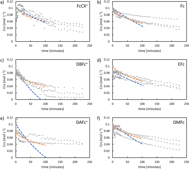
Additionally, despite having similar half-wave potential and Deff, DBFc+ had much higher conversion and rate constant than FcCX+ (Table IV). This outcome suggests that the rate of chemical delithiation is not dependent simply upon overpotential or Deff of the redox shuttles. The potential difference between these two redox shuttles was only 20 mV, which for an electrochemical cell that difference in driving force would not be expected to have such a dramatic difference in the oxidation rate of LFP (an example of the difference in conversion for a much greater difference in potential for the electrochemical analogue experiment can be found in Supplementary Material, Fig. S9a). Given that the redox shuttles also have very similar Deff in the electrolyte and that the same electrolyte and electroactive particles were used for the experiments, this outcome suggests there must be redox shuttle-particle interactions that are significantly impacting the reaction rate. The other redox shuttle evaluated for oxidation of LFP was DAFc+, which based on half wave potential had the greatest overpotential relative to LFP of ∼300 mV. DAFc+ had the highest rate constant and the most rapid initial oxidation of LFP over the first ∼10 min of the reaction, however, the redox reaction plateaued and the final conversion after 100 min was lower for DAFc+ compared to DBFc+, even though DAFc+ has a much greater overpotential (Fig. 2). An additional consideration for DAFc+ was that it was observed to form a highly viscous solution (see Supplementary Material, Fig. S10), which resulted in the low diffusion coefficient (Table I). Thus, these results suggest that DAFc+ has high initial conversion, but that a stability limitation may be limiting the conversion that can be achieved in the redox reaction. The results above, when combined, suggest that in cases where excess overpotential of the shuttle does not drive the reaction faster, it may be desirable to focus more on other metrics of the system where the redox shuttles and solid electroactive particles are being used, such as the stability and solubility of the redox shuttles in the electrolyte. The fundamentals behind the redox shuttle-particle interactions will be the subject of future investigations. The nature of such interactions will likely be challenging to probe experimentally. Computational approaches that provide insights into the electron transfer process for explicit molecular orientations of the redox shuttles at the solid electroactive material surface and for explicit chemical moiety modifications, combined with experimental assessment of reactions with the same redox shuttles, may provide supporting evidence for these effects.
Figure 2. Redox shuttle concentration, Crs, as a function of time during chemical redox reaction with LFP or FP. Initial concentrations for the redox shuttles were 100 mM of a) ferrocenium carboxaldehyde (FcCx+), b) ferrocene (Fc), c) dibromoferrocenium (DBFc+), d) ethylferroene (Efc), e) 1,1'-diacetylferrocenium (DAFc+) and, f) 1,1'-dimethylferrocene (DMFc). Note that a), c), e) are for oxidation of 200 mM LFP and b), d) and, f) are for reduction of 200 mM FP. The grey dots represent experimental data from triplicates and the dashed lines represent the JMAEK kinetic model (blue) and 1-D kinetic model (orange) back fitted for first 100 min of the reaction.
Download figure:
Standard image High-resolution image
With regards to the stability of the redox shuttles, it has been previously reported that the stability of ferrocenes or ferrocenium ions is dependent upon the nature of substituents. 38,47 Electron donating groups such as methyl/ethyl promote stability whereas electron-withdrawing groups such as acyl decrease stability. An unstable ferrocenium ion has been shown to decompose into Fe (Ⅱ) and Fe (Ⅲ) ions under acidic conditions. 48 While several reports have shown comparable diffusion coefficients of ferrocene and acyl substituted ferrocenes, these have been limited to concentrations of 10−3–10−2 M, and it is possible that instability effects such as side reactions with the electrolyte or dimerization become more pronounced at higher concentrations. Side reactions of the redox shuttles may have been the cause of the observed turbidity in the 100 mM DAFc+ solution during electrochemical oxidation (Supplementary Material, Fig. S10).
Reduction/lithiation of FP
Similar to chemical delithiation/oxidation of LFP, lithiation/reduction of FP under different solid particle ratios and using different redox shuttles was evaluated. For every reaction condition, the conversion of FP to LFP of ∼20% was achieved. This indicates that conversion in the case of chemical lithiation and reduction of FP was relatively insensitive to relative molar ratios of redox shuttle to FP, the overpotential (driving force), and the diffusion coefficient of redox shuttles (Tables I–III). Also, the reduction of FP with redox shuttles was generally slower than the oxidation of LFP. A few causes are speculated to have resulted in these observations. First, the FP was prepared from a prior chemical oxidation/delithiation step of LFP. While care was taken during this material preparation step (e.g., stirring was avoided), this process has been previously demonstrated to impact the surface composition and morphology of the LFP/FP material. 31 Though not as pronounced as the prior report which had significant stirring during chemical oxidation, the initial discharge with the FP prepared from chemical oxidation had greater polarization and less gravimetric capacity than the initial discharge of the as-received LFP at the same rate (Supplementary Material, Fig. S11). A surface more resistive to electron transfer, and chemically distinct form the initial LFP surface, may have been responsible for the reduced reaction rate and conversion for the FP reduction/lithiation relative to LFP oxidation/delithiation. This resistive surface layer may have also reduced the impact of different reaction conditions to substantially modify the chemical redox rate. It is noted that the first discharge polarization curve and reduced rate capability for the FP material would support the speculation (Supplementary Material, Fig. S3). Another difference to consider between the reduction/lithiation of FP and oxidation/delithiation of LFP is the direction and accessibility of Li+ during the reaction. For oxidation of LFP, the net change in oxidation state of the Fe in the LFP would be expected to provide a repulsive driving force for Li+ to leave the structure, and the immediate redox shuttle in the vicinity would be net neutral charge. However, for reduction/lithiation of FP Li+ must arrive from the surrounding electrolyte. There is significant excess of Li+ in the electrolyte phase, however, the molar concentration is much lower than in the solid phase of the LFP.
The redox reaction rate was similar across all redox shuttles, even though they had varying half-wave potentials (e.g., overpotential driving force, which relative to FP to LFP reaction ranged from 200 to 350 mV) and effective diffusion coefficients. The lack of a dependence on the effective potential of the redox shuttles contrasted with electrochemical lithiation of FP, where potentiostatic reduction of FP at 3.15 V vs Li/Li+ (∼350 mV overpotential) was significantly slower than potentiostatic discharge at 3.25 V vs Li/Li+ (∼200 mV overpotential). The electrochemical FP reduction results for FP can be found in Supplementary Material, Fig. S9b. This outcome suggests the potential of the redox shuttles may not be as important to modifying the rate of chemical redox relative to how the applied electrochemical potential impacts the electrochemical redox rate for LFP/FP. More redox shuttles need to be evaluated under different reaction conditions to confirm the generality of this observation, but given the importance of redox shuttle potential for many applications where redox shuttle-electroactive particle redox reactions would be taken advantage of, such as a for a redox shuttle mediated flow battery, relatively low sensitivity of the reaction rate to the redox shuttle potential would simplify the design of the overall system. 33
Alternative one-dimensional kinetic model
When the results from obtaining the kinetic parameters from JMAEK analysis were applied for comparison to the experimental outcomes (Fig. 2 and Supplementary Material, Fig. S8), in many cases the first 100 min of reaction had a good match. For example, the R2 for reduction of FP cases was more than 0.9 suggesting a good representation of the model in capturing the early portion of the reaction progression. However, for some cases, especially oxidation of LFP with the two shuttles besides DBFc+, the match between the JMAEK kinetic model and the experimental outcomes was not as good and the R2 was less than 0.9. This suggested that JMAEK may not have been an appropriate model for these cases, and other reports have suggested that JMAEK does not always provide an appropriate description for chemical redox of LFP/FP materials. 12
Towards achieving a better match with the experimental data, an additional model of the system was explored. This model was based on a one-dimensional (1-D) diffusion model within the batch reactor system. The system of equations can be found in the Supplementary Information, and some key assumptions of model were a) uniform spatial distribution of redox shuttle and Li+, b) LFP/FP particles were spheres with a uniform radius, and c) the rate of reaction has a first order rate dependence upon internal diffusion of Li+ into the LFP/FP particle. This model does not have a dependence on overpotential, and assumes stoichiometric changes in Li+ and redox shuttle changes in the liquid phase, and then matches the Li+ concentrations in the solid phase through balancing the flux of Li+ at the solid particle interface which is dictated by the rate of the redox reaction. The Li+ also must also diffuse through the solid particle, which is assumed to proceed through diffusive processes defined using spherical 1-D transport governed by Fick's law, 49 and a solid phase Li+ diffusion coefficient for LFP from the literature was used. 50 The rate constants (k') derived using the 1-D model for different reaction conditions used in this study can be found in Table V.
Table V. Rate constants from different reaction conditions extracted from fitting a 1-D diffusion model to experimental measurements of the reaction progression with time. k' was normalized by the surface area of solid electroactive particles added.
| FePO4 + RSred + Li+ → LiFePO4 + RSred + | LiFePO4 + RSox + → LiFePO4 + RSox + Li+ | |||
|---|---|---|---|---|
| Solid Particle: Redox Shuttle (mol:mol) | RSred | k' × 10−13 (m−1 s−1) | RSox + | k' × 10−13 (m−1 s−1) |
| 1:2 | Ferrocene (Fc) | 0.43 | 1,1'-Dibromoferrocenium (DBFc+) | 2.43 |
| 1:1 | Ferrocene (Fc) | 1.21 | 1,1'-Dibromoferrocenium (DBFc+) | 15.34 |
| 2:1 | Ferrocene (Fc) | 0.96 | 1,1'-Dibromoferrocenium (DBFc+) | 4.50 |
| 2:1 | 1-Ethylferrocene (EFc) | 0.85 | Ferrocenium Carboxaldehyde (FcCX+) | 0.66 |
| 2:1 | 1,1'-Dimethylferrocene (DMFc) | 0.80 | 1,1'-Diacetylferrocenium (DAFc+) | 16.67 |
The 1-D model had a significantly better fit (R2 > 90% for all conditions) of the experimental data compared to the JMAEK model (Fig. 2 and Supplementary Material, Fig. S8), particularly the cases where the initial rate of reaction was faster as was the case for some of the experiments of oxidation of LFP. The fit of the experimental data was improved, although the general trends for rate constants (k* for JMAEK and k' for the alternative 1-D model) were similar. In particular, k' was also greatest for the equimolar scenario in the experiments evaluating the influence of the solid particle:redox shuttle molar ratios and the k' values were generally greater for oxidation of LFP compared to reduction of FP, consistent with k* values. However, the relative magnitudes of differences of the rate constants for different reaction conditions was different for the JMAEK and 1-D model. For example, the rate constant for delithiation using DBFc+ vs FcCX+ is 7 times higher using 1-D model, compared to twice as high using JMAEK. The 1-D model thus suggests even greater sensitivity to specific particle-redox shuttle interactions, as this was the case where the differences in redox potential and Deff between the shuttles was relatively small. While this 1-D model is an initial effort to better describe the experimental outcomes from chemical redox between redox shuttles and solid electroactive materials, it highlights that results from JMAEK should be carefully assessed and compared with the measured conversion as a function of time to determine if such analysis is appropriate.
Conclusions
In this work, chemical redox of solid electroactive materials using redox shuttles was investigated. The Li-ion cathode material LFP/FP was used as the solid material, and the influence of different solid particle:redox shuttle molar ratios and the use of different redox shuttles was analyzed using an electrochemical cell and technique to track progression of conversion of the redox shuttle. It was found that for the batch reactor system employed that equimolar feeds of solid particles and redox shuttles resulted in the highest conversion, and the oxidation of LFP was generally faster than the reduction of FP. In comparative analysis of the different redox shuttles, there were cases where even though the differences in electrochemical potential and diffusion coefficient of the redox shuttles were modest, the reaction rates were significantly different. This suggests there are specific redox shuttle-particle interactions that are influencing the reaction rate. The conversion data for the different reaction conditions was also evaluated using the JMAEK model and an alternative 1-D kinetic model. Both models provide access to rate constants for relative comparison between the redox shuttles, where JMAEK values can be compared to the existing literature for chemical redox of LFP/FP and the 1-D model had a better fit to the experimental data. This study provided an experimental system which took advantage of electrochemical analysis to evaluate the relative reaction rates of redox shuttles used to chemically oxidize/reduce Li-ion active materials, which is relevant to applications such as redox mediated flow batteries and overcharge protection in Li-ion cells. This method, and the analysis to extract rate constants for ease of comparison between redox shuttles, provides a robust approach to comparing candidate redox shuttle compounds.
Acknowledgments
The authors acknowledge funding from the National Science Foundation, grants No. 1940915 and No. 1652488.
Appendix
Supplementary Material.