
Abstract
The identity of passivating oxides on multi-principal element alloys is of great interest as their optimization offers the potential for exceptional corrosion resistance in aqueous solutions over a broad range of potential and pH. This study focuses on a non-equiatomic Ni38Fe20Cr22Mn10Co10 solid solution alloy and tracks the fate of each alloying element during linear sweep voltammetry, low and intermediate potential holds in the passive potential domain as well as during open circuit relaxation after anodic polarization in slightly acidified Cl− solution. Ni dissolves at all potentials investigated in this work, Fe and Co are incorporated into oxides or hydroxides in low concentrations whilst Cr and Mn are enriched at passive potentials. At low passivating potentials, Mn(II) dissolves and is incorporated in minor amounts in oxides containing large concentrations of Cr(III). Considerable enrichment in Mn(II)-species occurs relative to Cr(III) in the oxide at 0.1 V vs SCE. Electrochemical impedance spectroscopy suggests the presence of layered oxides with marginal passivation at high Mn(II) levels. The formation of these oxides depends on a combination of thermodynamic and kinetic factors as well as the sequence of passivation.
Export citation and abstract BibTeX RIS
Multi-principal element alloys (MPEAs) have exhibited a range of outstanding mechanical properties as well as promising catalytic attributes. 1,2 In some cases, emerging information on high corrosion resistance of the MPEAs 3,4 suggests the possibility of utilization in harsh environments. For instance, these materials may be considered for nuclear waste container applications 5 due to potentially high corrosion resistance, high strength, and thermal/radiation-damage resistance. 6,7 In contrast to conventional corrosion resistant alloys, 8,9 MPEAs enjoy a large compositional design space because of the possible formation of a single solid solution or two-phase structure over a range of alloying element compositions. 10 Single phase MPEAs are attributed to the high mixing entropy, which can enhance solid solution phase stability and chemical homogeneity. 4,11 Other factors such as grain orientation, short range order vs random solid solution, interfacial properties, and interphase heterogeneity undoubtably affect corrosion but have yet to be explored extensively.
Given the large concentrations of all principal elements in equiatomic alloys (possibly greater than 20 at.% for 5 elements or less), there is high potential for passive film formation due to either dominant single element containing near-stoichiometric or complex oxides at a variety of potentials, pH levels and in various electrolytes as suggested by potential-pH (E-pH) diagrams. 8 However, material design for corrosion resistance remains unclear as both scientific details and figures of merit and are uncertain. 10 Identifying the contribution of the individual alloying elements to the passivation and dissolution resistance of the MPEAs is critical to understanding the corrosion behavior of the MPEAs. In this study, we explore one specific alloy within the Fe-Ni-Co-Cr-Mn MPEA system which is a well reported system with significant metallurgy, high temperature oxidation and aqueous corrosion data existing in the literature. 12–17
For Cr containing MPEAs, Cr(III) enrichment in the oxide film has been observed. 18,19 Cr is often considered to be the main element contributing to the stable passive film formation in numerous transition metal alloys, as in the case of conventional Ni-Cr alloys and stainless steel. 20–22 Cr 2 O 3 has one of the lowest free energies of formation of the single element oxides in binary as well as Cr-Mn-Ni-Co-Fe MPEAs. 23 Moreover, thermodynamic calculations suggest Cr-based corundum and spinel oxides hosting multi-element solid solutions are the most stable oxide phases over broad E-pH regions. 8,24 Corundum (Fe, Cr) 2 O 3 , spinel (Fe, Ni, Cr, Mn, Co) 3 O 4 , cubic (Co, Fe) 2 O 3 , and (Ni, Mn) 2 (Ni, Mn, O) 3 oxide solid solutions with space group Ia3 (prototype cubic Mn 2 O 3 ), are stable over large portions of the E-pH diagram for a particular Ni38Fe20Cr22Mn10Co10 MPEA. 24 However, Cr containing MPEAs have sometimes been found to possess inferior corrosion resistance compared to stainless steels. 25 Reports of both high and low corrosion resistance and high or low Cr-based oxide concentrations in oxides in similar Ni-Fe-Cr-Mn-Co MPEAs render any blanket generalizations regarding corrosion protection afforded by Cr alloying as untenable. 25–29
The role of Mn in the alloys is relatively less well understood. Mn has been added to the stainless steel as it is a well-known austenite stabilizing element, 30 and also attractive for designing face-centered cubic (FCC) MPEAs. However, formation of MnS inclusions causes significant degradation in corrosion resistance of the stainless steel. 31–33 The effect of Mn on high temperature oxidation of both Fe-Mn-Cr and MPEAs is relatively well established. 27,34,35 It is noteworthy that multi-phase oxides of Cr and Mn in Fe alloys are relatively less protective than Cr oxides without Mn during high temperature oxidation, attributed to fast Mn cation transport across Mn oxides and surface enrichment with attendant Mn depletion in the underlying alloy. 27,30,31 Voids, spalling, and destabilization of the FCC alloy are also observed during high temperature (T > 600 °C) oxidation of Ni-Fe-Cr-Mn-Co MPEAs. 14,36
Adding Mn to Fe-Ni-Co-Cr single phase alloys is uniformly detrimental across a variety of alloys, electrolytes and passivating procedures aside from the benefit of stabilizing the FCC solid solution. For instance, adding Mn to an equimolar Cr-Fe-Co-Ni MPEA resulted in more severe pitting corrosion than without Mn in 0.1 M NaCl 26 and poor passivation in 0.1 M H 2 SO 4 solution. 25,27 Yang et al. compared Fe-Ni-Co-Cr alloys with and without Mn and observed that the presence of Mn resulted in degraded film stability and decreased electrochemical impedance at low frequency in a 0.1 M H 2 SO 4 solution. Rodriguez et al. investigated a series of (FeNiCo) 1−x−y (Cr) x (Mn) y alloys ranging from x + y = 0.23 to 0.40 (in molar fraction), in a pH = 4, 3.5 wt.% NaCl solution at T = 40 °C. a They found that alloying with a Mn content greater than 13–15 at.% resulted in decreased corrosion performance with higher corrosion current density, and lower pitting potential. The least corrosion resistant alloy contained no Cr while incorporating 25 at.% Mn. In spite of all the composition variations a critical threshold Cr at.% could not be estimated, however, it was found that high Mn was detrimental to the passivity. That said, a Ni38Fe20Cr22Mn10Co10 MPEA exhibited similar passivation behavior to Ni-20 at.% Cr 28 in 0.1 M NaCl at pH = 4. It is noteworthy that Mn content was, in this case, only 10 at.%.
Mn undergoes anodic oxidation readily as Mn2+ in an acidic solution at potentials below the reversible potentials for both water and oxygen reduction, according to thermodynamic predictions. 24,37 This prediction has been experimentally demonstrated: Mn was depleted in the passive film of the 304 austenitic stainless steel in 2.0 M H 2 SO 4 monitored by atomic emission spectroelectrochemistry (AESEC). 38 Mn-based oxides were characterized in the passive film by X-ray photoelectron spectroscopy (XPS) after 6 h immersion in 10 wt.% H 2 SO 4 in the case of Fe-xMn (x = 0.70, 2.0, and 5.0 wt.%) alloys. 30 It was concluded that the addition of 5.0 wt.% Mn to the steel resulted in the formation of a protective oxide, which increased the corrosion resistance characterized by electrochemical measurements. 30 For Fe-18Cr-xMn alloys (x = 0, 6, and 12 wt.%) in a 0.1 M NaCl solution at pH = 2, the passive film formed for the higher Mn content alloy resulted in a lower pitting potential, 31 indicative of a less protective oxide. It was concluded that Mn additions may suppress the passivation process by reducing the activity of adsorbed Cr species. The correlation between high or low Mn content in oxides on corrosion behavior may depend on alloy, environment, passivation steps, and most importantly, low vs high potentials. At low passivating potentials, Cr-rich oxides were observed with some Mn incorporation. 31 However, at higher potentials, more Mn oxides were seen coincident with the thermodynamic stability of Mn 3 O 4 , Mn 2 O 3 , or Mn-containing spinels over a broader pH range. 24,28 Concerning Cr, one study found Cr oxide contents lower than the alloy composition, and in another study much higher Cr oxide content even at high anodic potentials. 25,39
A more comprehensive investigation of the role of Mn and Cr is required to understand its role in the corrosion resistance of FCC MPEAs that often incorporate these elements. The first step in this process is to track the fate of alloyed Mn in the altered layer as well as the inner and outer layers of the passive films along with Cr.
We began our studies with a limited investigation into a single-phase Ni38Fe20Cr22Mn10Co10 MPEA alloy for simplicity in the Ni-Fe-Cr-Mn-Co family as previously reported. 28 Tracking methods in both oxide and solution are required with elemental specificity. XPS considering core level analysis and outer shell studies has been shown to be necessary. 39 AESEC is used for mechanistic investigation of MPEAs as it directly measures the elemental dissolution rate of each alloying elements coupled with all AC and DC electrochemical measurements. This technique is useful, in particular, for the selective dissolution in multi-phase alloys 40 and passivation of Ni-based alloys [22]. 41–44 It was recently deployed to examine a nearly equiatomic Al-Ti-V-Cr MPEA in Cl--containing media, 45,46 equiatomic Co-Cr-Fe-Mn-Ni in 0.1 M H 2 SO 4 , 25 and non-equiatomic Ni-Cr-Fe-Ru-Mo-W in 2 M H 2 SO 4 . 47 In combination with ex situ XPS surface characterization of the outer layers of oxidized surfaces, AESEC provides a powerful approach to understand the fate of each alloying element.
In this work, the fate of the alloying elements, whether dissolved in the solution or remaining at the surface (in the oxide or metal), was investigated for a Ni38Fe20Cr22Mn10Co10 MPEA in 0.1 M NaCl, at pH = 4.0. It is generally observed that Cr is enriched in the passive film in the case of Ni-Cr alloys as well as stainless steels. 20–22 Cr enrichment during the early stages of passivation was previously monitored by mass-balance calculation via AESEC, confirmed by ex situ XPS and 3D-atom probe tomography (3D-APT) for a Ni38Fe20Cr22Mn10Co10 MPEA in 0.1 M NaCl at pH = 4.0. 28 However, for the Fe-Ni-Co-Cr-Mn MPEAs, either Cr depletion or enrichment has been reported in the passive films under different conditions. 19,29 In this work, we demonstrate that Mn in a Ni38Fe20Cr22Mn10Co10 MPEA showed potential dependent oxide enrichment in 0.1 M NaCl at pH = 4.0. Elements dissolved or accumulated in an oxidized state at the surface for a given potential were observed by in situ AESEC and ex situ XPS experiments. These were correlated with AC and DC electrochemistry and discussed in the context of thermodynamic and kinetic oxide factors controlling oxide composition. Potential dependent Mn enrichment in oxides was found to reduce the electrochemical impedance of the oxides formed and lower corrosion resistance.
Experimental
Materials
The Ni38Fe20Cr22Mn10Co10 MPEA was produced using a computational design approach and characterized in our previous work. 9 A Ni78Cr22 binary alloy was also investigated for comparison. All alloys were arc-melted, then solution heat treated at T = 1100 °C for 96 h followed by water quenching. The alloy exhibited a compositionally homogeneous single-phase FCC characterized by energy dispersive spectroscopy (EDS) mapping and X-ray diffractometry (XRD). The sample surface was initially degreased with isopropanol in an ultrasonic bath for 15 min, rinsed with deionized (DI) water (MilliporeTM, 18.2 MΩ cm), and then dried with flowing N 2 . The sample surface was ground with SiC paper up to P4000 under DI water then dried by flowing N 2 again. The 0.1 M NaCl electrolyte was prepared from analytical grade materials in DI water. The final electrolyte pH was adjusted to 4.0 by adding 1.0 M HCl solution. The electrolyte pH was chosen to represent a slightly acidic corrosive environment based on the thermodynamic simulation. 24 At this pH, thermodynamically stable soluble species of the alloying elements as well as non-soluble species will be present in a wide potential range. This pH is aggressive to challenge and interrogate passivity under conditions that were not benign, for comparison for stainless steel. The electrolyte was deaerated by bubbling Ar gas for 30 min prior to and during the experiments. All the experiments presented in this work showed reproducible results from at least three repeated experiments.
AESEC technique
The elemental dissolution rate of each alloy component of the MPEA during the electrochemical test was monitored in situ, by the AESEC technique. The principles and detailed calculations used in this technique are available elsewhere. 43,48 The sample was placed vertically in a specially designed electrochemical flow cell 49 where the released cations were transferred within the electrolyte to an Ultima 2C Horiba Jobin-Yvon inductively coupled plasma atomic emission spectrometer (ICP-AES). A reference electrode (saturated calomel electrode, SCE) and a counter electrode (Pt foil) were positioned in a reservoir separated from the working electrode by a porous membrane enabling ionic current to pass between the two compartments but preventing bulk mixing. 43,48
A Gamry Reference 600TM was used for the electrochemical tests. The ICP-AES data acquisition system was specially adapted to measure the analog current and potential signals from the potentiostat in the same data file as the dissolved elemental emission intensities to facilitate the direct comparison between spectroscopic and electrochemical data. 43
Data analysis
The detailed data analysis of the AESEC technique is presented elsewhere. 43 The elemental concentration, C M , was calculated from the atomic emission intensity, I M, λ , at a characteristic wavelength of the element, λ, measured by the ICP spectrometer as:

where I M, λ ° is the background signal and κ λ is the sensitivity factor for a given element, obtained from a standard ICP calibration method. The elemental dissolution rate per unit area, v M , can be calculated from C M with the flow rate (f) of the electrolyte controlled by a peristaltic pump and the exposed surface area A as:

It is often convenient to present the elemental dissolution rate as an equivalent elemental current density (j M ) using Faraday's law:

where M M is the atomic weight of M, F is the Faraday constant, and z M is the valence of the dissolving ions for oxidation such as M → Mz+ + z M e−. The oxidation states of the dissolved M in 0.1 M NaCl, pH = 4 environment are assumed from thermodynamic prediction as Ni(II), Fe(II), Cr(III), Mn(II), and Co(II). 24 It is often convenient to present the normalized elemental current densities (j M ') based on the bulk composition relative to j Ni as:

where X M is the mass fraction of the element in the bulk alloy. Congruent dissolution is indicated when j M ' = j Ni ; otherwise non-congruent dissolution is suggested. When j M ' < j Ni , M is being retained as a corrosion product or does not completely oxidize while when j M ' > j Ni preferential dissolution of M is indicated.
The total quantity of dissolved element M, Q M (t), may be calculated as:

The quantity of the excess element M remained at the surface (Θ M ) relative to Ni was calculated by a mass-balance as:

It is worth mentioning that the interference between AESEC intensity signals of Fe (259.94 nm) and Mn (257.61 nm) were assessed by an individual experiment using the ICP-AES method in the case of a standard solutions of known concentration. The interference of Fe signal to Mn was found to be negligible (< 0.6 %), therefore, Fe and Mn signals were not corrected in this work.
X-ray photoelectron spectroscopy (XPS)
The samples were characterized ex situ by XPS using PHI-VersaProbe IIITM X-ray photoelectron spectrometer using an Al Kα X-rays (1468.7 eV) under analysis pressure less than 10–8 bar. A survey of XPS was conducted with a pass energy of 224 eV to obtain the maximum number of counts. A pass energy of 26 eV was used for the high-resolution spectra. XPS spectra was analyzed with KOLXPDTM software. Both XPS 2p and 3p core level spectra were obtained to characterize the sample surface after the electrochemical tests. The 3p core level peak analysis has an advantage in this work because the 2p peaks for Ni-Fe-Cr-Mn-Co MPEA have interference with the Auger transitions from some of the other alloying elements. 39
Electrochemical analysis
The electrochemical impedance spectroscopy (EIS) was conducted after potentiostatic experiments (not coupling with AESEC) in the frequency range from 105 to 10–2 Hz. Potentiostatic EIS was carried out at a given potential after a potentiostatic hold for 4000 s at that potential, following to a cathodic reduction step at −1.3 V vs SCE for 600 s. The data were recorded with 8 points per decade using a 10 mVrms sine wave perturbation. The electrolyte resistance (R e ) was corrected from the real part of impedance (R r ) before the Bode plot construction for graphical analysis of constant-phase element (CPE) parameters 50 as well as model circuit fitting.
The linear sweep voltammetry (LSV) was performed with following procedure; 1) a constant potential at E ap = −1.3 V vs SCE was applied for 600 s to minimize the effect of air-formed oxide; 2) the potential was swept from −1.3 V to 0.8 V vs SCE with 0.5 mV s−1 scan rate; and 3) spontaneous dissolution rates during open circuit exposure as well as open circuit potential were recorded.
Results
Elemental dissolution rates during upward potential sweep
Figure 1 reports the elementally resolved polarization data enabled by coupling AESEC with conventional linear sweep voltammetry (LSV), denoted as AESEC-LSV. The results are presented for the Ni38Fe20Cr22Mn10Co10 MPEA in deaerated 0.1 M NaCl at pH = 4.0. The normalized elemental dissolution rates (j M ') are presented as equivalent dissolution current densities to facilitate comparison (Eqs. 3 and 4) with the net electrical current density, j e , obtained from the potentiostat. Figure 2 shows a close-up in the vicinity of the zero-current potential (E j=0 ) in the AESEC-LSV.

Figure 1. AESEC-LSV of the Ni38Fe20Cr22Mn10Co10 MPEA in a deaerated 0.1 M NaCl, pH = 4 solution with 0.5 mV s−1 scan rate. Prior to the LSV measurement, a constant potential at E ap = −1.3 V vs SCE was applied to reduce the pre-existing air-formed oxide. After the potential release, elemental dissolution rates were recorded during open circuit measurement (E oc relaxation). Normalized elemental dissolution rates equivalent to current densities (j M ') using Eq. 4 are given to demonstrate deviations from congruent dissolution.
Download figure:
Standard image High-resolution image
Figure 2. Results from AESEC-LSV of the Ni38Fe20Cr22Mn10Co10 MPEA in a deaerated 0.1 M NaCl, pH = 4 solution. j M ', the sum of j M (j Σ ) and electrical current density (j e ) magnified in the active and passive potential domains from Fig. 1 are presented. j M ' curves are given with offset. Horizontal lines indicate zero value (j M ' = 0). Dashed line indicates the j Ni to determine congruent dissolution of each alloying element. If j M ' equals to the dashed line, that may indicate congruent dissolution of M. If j M ' is lower than the dashed line, dissolution of M is non-congruent.
Download figure:
Standard image High-resolution imagePrior to the AESEC-LSV, a constant potential of E ap = −1.3 V vs SCE was applied for 600 s to minimize the pre-existing air-formed oxide. All five elemental dissolution rates showed two distinctive elemental dissolution rate peaks in the cathodic reduction step, indicating that the dissolution was associated with the electrochemical process. This was distinct from the perturbations of the j e signal which may be related to the hydrogen evolution reaction as shown for other Ni-based alloys and an MPEA in a similar potential range. 22,42
The AESEC-LSV results in the potential range from −0.7 V to 0.3 V vs SCE are magnified in Fig. 2 including active and passive potential domains. The Ni dissolution equivalent current density, j Ni , is shown as a dashed curve to indicate what the congruent dissolution rate of each element would be assuming complete Ni dissolution as described in the experimental section. The onset of anodically polarized elemental dissolution occurred slightly below E j=0 , near −0.46 V vs SCE. The sum of j M (j Σ = j Ni + j Fe + j Cr + j Mn + j Co ) is also presented in the top panel of Fig. 2. j e is the equivalent faradaic electrical current density obtained by potentiostat, simultaneously with the AESEC elemental dissolution rates (j M ). The formation of oxides is suggested by j Σ < j e while j Σ > j e may be due to either a significant cathodic current or a non-electrochemical dissolution mechanism. For E > E j=0 , two anodic peaks were observed near E = −0.25 V (a 1 ) and E = −0.15 V vs SCE (a 2 ). The total elemental dissolution was nearly faradaic, indicated by j Σ ≈ j e near a 2 . At potentials above a 2 , the formation of a passive film is indicated by j Σ < j e in the passive potential domain. Selective Ni, Fe and Co dissolution is suggested in the passive potential domain where j M ' = j Ni (M = Ni, Fe, and Co) while non-congruent Mn and Cr dissolution is indicated by j M ' < j Ni (M = Mn and Cr). The latter may be due to the accumulation of oxidized Mn, and Cr species on the surface, probably in a form of oxide or hydroxide. In the potential domain above the passive potential range (Figs. 1 and 2), Mn and Cr continued to exhibit non-congruent dissolution as shown in the passive domain.
After AESEC-LSV, the spontaneous elemental dissolution rates and the corresponding open circuit potential were recorded (Fig. 1). Monitoring elemental dissolution rate in this period can give insight into the elements joining the passive film formed during the polarization experiment and subsequent relaxation. 22,42,51 Only Mn showed less than congruent dissolution (j Mn ' < j Ni ) in this period suggesting a continual build-up of Mn on the surface during the E oc relaxation.
Elemental dissolution and passivation at a constant potential
Two potentials in the passive potential domain were chosen from Fig. 2 (i.e., 0.0 V and 0.1 V vs SCE). AESEC chronoamperometry (AESEC-CA, Fig. 3) was conducted while the net anodic current was monitored from the potentiostat. Previously, a significant Cr enrichment in the early stage of passivation was observed at a more negative potential (E ap = −0.25 V vs SCE) in the same electrolyte for the Ni38Fe20Cr22Mn10Co10 MPEA. 28
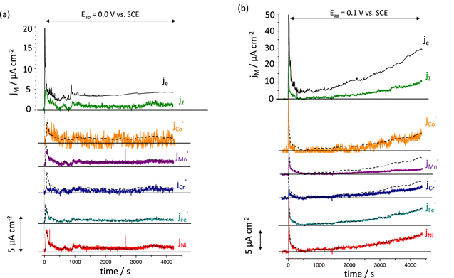
Figure 3. AESEC chronoamperometry (AESEC-CA) of the Ni38Fe20Cr22Mn10Co10 MPEA at a passive potential; (a) E ap = 0.0 V, and (b) E ap = 0.1 V vs SCE in 0.1 M NaCl, pH = 4.0, deaerated solution, after a cathodic reduction at E ap = −1.3 V vs SCE for 600 s. The vertical dashed line indicates t = 0 when the potentiostatic hold started after the cathodic reduction step.
Download figure:
Standard image High-resolution imageFigure 3a gives the AESEC-CA at E ap = 0.0 V vs SCE with j M ', j e and j Σ measured after a cathodic potential hold for 600 s. The complete elemental oxidation was not accounted for by dissolution shown as j e > j Σ , which may indicate passive film formation. j e as well as j M approach stable values, indicative of a steady state between passive film formation and dissolution. Mn and Cr showed non-congruent dissolution with j M ' < j Ni (dashed line) for the initial 100 s indicating their retention on the surface. Non-congruent Cr dissolution was also observed (j Cr ' < j Ni ) throughout the AESEC-CA experiment indicating a continuous Cr-species surface accumulation.
For E ap = 0.1 V vs SCE (Fig. 3b), passive film formation is again suggested by j Σ < j e . In this case, however, passive film dissolution or local breakdown and pitting may be faster than oxide formation as both j e and j M ' increased with time. Cr and Mn again showed non-congruent dissolution as both j Cr ' and j Mn ' were lower than j Ni throughout the measurement. This is in agreement with the previous AESEC-LSV curve (Figs. 1 and 2) where non-congruent Cr and Mn dissolution were observed at 0.1 V vs SCE, indicating Cr- and Mn-based passive film formation.
Further insight into the surface enrichment may be obtained by the mass-balance (ΘM) of AESEC results calculated from Eq. 6, shown in Fig. 4. At E ap = 0.0 V vs SCE, the excess amount of oxidized Cr (Θ Cr ) increased with time to approximately 150 ng cm−2 after 4000 s. At E ap = 0.1 V vs SCE (Fig. 4b) the Θ Cr was approximately 500 ng cm−2, and Θ Mn ≈ 290 ng cm−2 at the end of the experiment. The fraction of the excess alloying element at the surface during the AESEC-CA experiment is estimated from Fig. 4, and shown in Fig. 5. In both cases, Cr enrichment occurred in early stage of passivation (after several hundred seconds) in accordance with previous observation. 28 Mn accumulation was much greater at E ap = 0.1 V vs SCE where the excess Mn at the surface increased as a function of time (Fig. 5b).
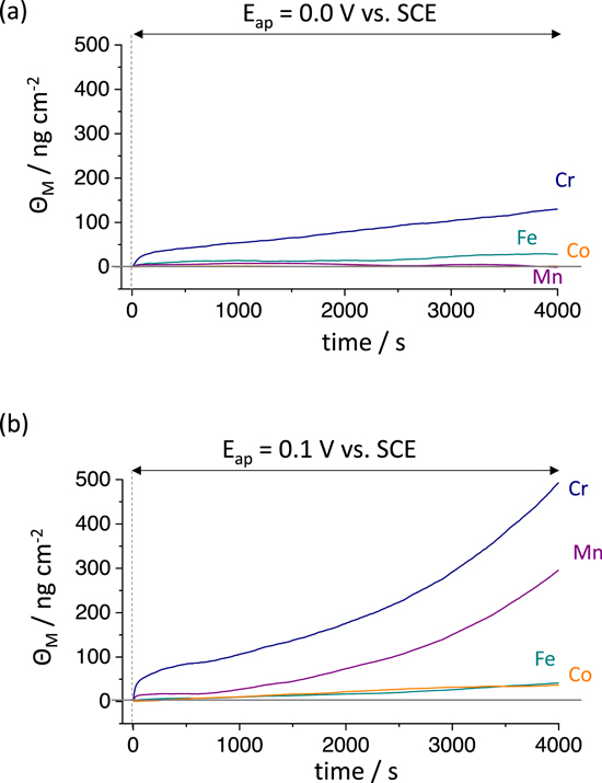
Figure 4. The excess element M (Θ M ) in ng cm−2 oxidized and residing in solid form at the alloy surface calculated by a mass-balance (Eq. 6) during each AESEC-CA experiment from Fig. 3; (a): E ap = 0.0 V vs SCE and (b): E ap = 0.1 V vs SCE. The vertical dashed line is t = 0 when the potentiostatic hold started after a cathodic reduction for 600 s.
Download figure:
Standard image High-resolution image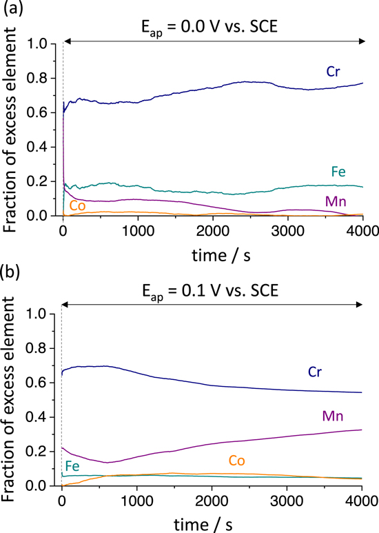
Figure 5. Surface cation fractions obtained from Fig. 4 of the Ni38Fe20Cr22Mn10Co10 MPEA during (a) E ap = 0.0 V vs SCE, and (b) E ap = 0.1 V vs SCE in 0.1 M NaCl, pH = 4, deaerated solution. The vertical dashed line indicates t = 0 when the potentiostatic hold started after a cathodic reduction for 600 s.
Download figure:
Standard image High-resolution imageDissolution and passivation kinetics at each potential compared to the Ni-Cr binary alloy
The electrochemical response of the Ni38Fe20Cr22Mn10Co10 MPEA was compared with that of a Ni-Cr binary alloy with the same at.% of Cr to investigate the effect of minor alloying elements such as Mn or Co. The electrical current density as a function of potential (LSV) is shown in Fig. 6a, and the current density decay during a constant potential hold in the passive potential domain is given in Fig. 6b. The dissolution and passivation kinetics during the potential hold experiments were investigated by potentiostatic EIS as shown in Fig. 7. The j e in the cathodic potential domain in the LSV curve (Fig. 6a) for the Ni38Fe20Cr22Mn10Co10 MPEA was lower than that of Ni78Cr22 binary alloy. The Ni78Cr22 binary alloy showed an anodic peak at a slightly more positive potential than that of the Ni38Fe20Cr22Mn10Co10 MPEA.
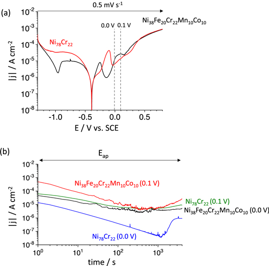
Figure 6. (a) LSV, and (b) current density vs time at the indicated constant potentials of the Ni38Fe20Cr22Mn10Co10 MPEA and Ni78Cr22 binary alloy in a 0.1 M NaCl, pH = 4, deaerated solution. Note that experiments were performed after 600 s at E ap = −1.3 V vs SCE to minimize the effect of the air-formed oxide.
Download figure:
Standard image High-resolution image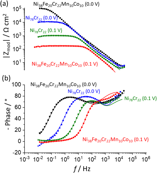
Figure 7. (a) Bode magnitude, and (b) phase plot after each 4000 s potentiostatic hold on the Ni38Fe20Cr22Mn10Co10 MPEA and Ni78Cr22 binary alloy, following a cathodic reduction at E ap = −1.3 V vs SCE for 600 s. Equivalent circuits used to fit the EIS spectra are given in Fig. 8 and the fitting results are shown by solid lines while the symbols represent the data points.
Download figure:
Standard image High-resolution imageFigure 6b gives the j e decay as a function of time (in log-scale for both je and time) when a constant potential of either 0.0 V or 0.1 V vs SCE was applied to the two alloys after 600 s of cathodic potential hold at E ap = −1.3 V vs SCE. The j e decay for the Ni38Fe20Cr22Mn10Co10 MPEA showed multiple metastable oxide breakdown events indicated by anodic perturbations in j e for t > 80 s at both applied potentials, whereas the Ni 78 Cr 22 binary alloy showed much fewer and lower perturbations in j e .
EIS was conducted after a potentiostatic hold for 4000 s at E ap = 0.0 V and 0.1 V vs SCE, after a cathodic potential hold for 600 s at −1.3 V vs SCE. These experiments provide insights into the dissolution kinetics as well as a possible oxide layer formation verified or corroborated independently by a simplified equivalent electrical circuit model, as shown in Figs. 7 and 8. The Bode plots and fitting results are presented in Fig. 7a. Layered oxide circuit models were used to simulate the effect of a duplex oxide, as reported for a near equiatomic Ni-Fe-Cr-Mn-Co MPEA following high temperature oxidation 52,53,54 and aqueous passivation at room temperature. 26,27,39 For a Ni38Fe20Cr22Mn10Co10 MPEA at E ap = 0.0 V vs SCE 27,39 and Ni78Cr22 binary alloy, 41,55,56 a two time-constant circuit model with constant-phase elements (CPE) was used; CPE 1 /R 1 represents the inner oxide and CPE 2 /R 2 represents the outer oxide, shown in Fig. 8a. For the Ni38Fe20Cr22Mn10Co10 MPEA at E ap = 0.1 V vs SCE, a circuit model with a relatively compact porous inner covered by an outer layer 57,58 was utilized (Fig. 8b). The CPE l, 1 represents the CPE contribution of the inner oxide, R l, 1 is the inner oxide resistance within the pore length, CPE dl is the double layer component at the interface in parallel with a faradaic impedance (Z F ), and CPE l, 2 /R l, 2 represents a thin outer oxide layer. Both circuits could be reasonably well fitted to the experimental data shown in Fig. 7. For the Ni38Fe20Cr22Mn10Co10 MPEA at E ap = 0.1 V vs SCE, the modulus impedance (Z mod ) in the low-frequency domain (f < 10–1 Hz, Fig. 7b) was three orders of magnitude lower than that observed for E ap = 0.0 V vs SCE. This was likely due to the formation of less protective Mn oxide as previously indicated by a non-congruent Mn dissolution, Figs. 3b and 4b, at this potential. Lower Z mod in the low-frequency domain at E ap = 0.1 V vs SCE was also monitored for the Ni78Cr22 binary alloy (Fig. 7b) as compared to that at E ap = 0.0 V vs SCE. For the Ni78Cr22, the difference in Z mod between two applied potentials was only one order of magnitude. The inner oxide resistance (R l, 1 ) of the Ni38Fe20Cr22Mn10Co10 MPEA at E ap = 0.1 V vs SCE obtained from the circuit model fitting using Fig. 8b was 1.6 x 10² Ω cm2 whereas that the inner oxide resistance (R 1 ) at E ap = 0.0 V vs SCE was 1.2 × 10⁵ Ω cm2 using Fig. 8a. This may indicate a less protective oxide at E ap = 0.1 V vs SCE compared to that at E ap = 0.0 V vs SCE for the Ni38Fe20Cr22Mn10Co10 MPEA.
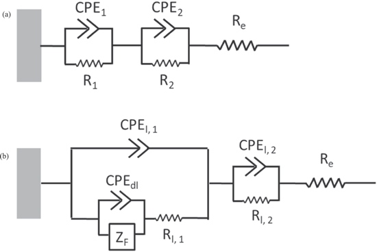
Figure 8. Simplified EIS circuit model to account for the EIS spectra of (a) Ni38Fe20Cr22Mn10Co10 MPEA at E ap = 0.0 V vs SCE and Ni78Cr22 binary alloy; (b) Ni38Fe20Cr22Mn10Co10 MPEA at E ap = 0.1 V vs SCE.
Download figure:
Standard image High-resolution imagePassive film characterization by XPS
The surface of the Ni38Fe20Cr22Mn10Co10 MPEA after each potentiostatic hold experiment was characterized by ex situ XPS, shown in Figs. 9 and 10. Analyzing the 2p XPS data for a Ni-Fe-Cr-Mn-Co based MPEA is difficult due to the overlap of 2p and Auger transitions. 39 To this end, the high-resolution XPS 3p core level spectra were obtained from 35 to 80 eV, shown in Fig. 10.
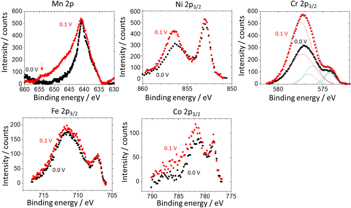
Figure 9. XPS spectra of Mn 2p, Ni 2p 3/2 , Cr 2p 3/2 , Fe 2p 3/2 , and Co 2p 3/2 for the Ni38Fe20Cr22Mn10Co10 MPEA after potentiostatic experiments at E ap = 0.0 V and 0.1 V vs SCE for 4000 s in 0.1 M NaCl, pH = 4.0, deaerated solution followed by an air transfer for XPS analysis.
Download figure:
Standard image High-resolution image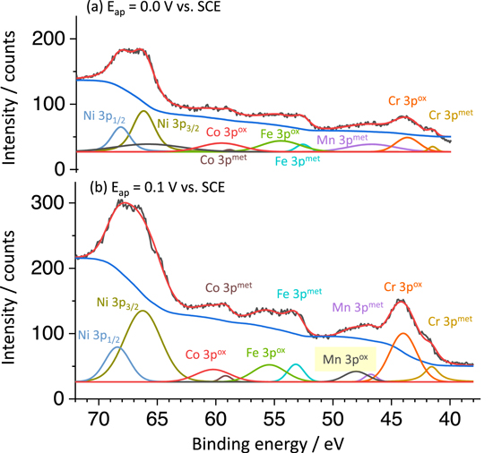
Figure 10. XPS 3p core level spectra of Ni, Fe, Cr, Mn and Co after potentiostatic hold experiments on the Ni38Fe20Cr22Mn10Co10 MPEA at (a) E ap = 0.0 V vs SCE, and (b) E ap = 0.1 V vs SCE for 4000 s in 0.1 M NaCl, pH = 4.0 deaerated solution.
Download figure:
Standard image High-resolution image
The Cr 2p3/2 spectra were analyzed because there is no interference between 2p Auger transitions from the other elements and 2p photoelectron signal of Cr. At both applied potentials, the Cr 2p3/2 spectra could be fitted by Cr(0) metallic (574.2 eV), Cr(III) hydroxide (577.3 eV), and Cr(III) oxide (576.2 eV) peaks. 59 For Mn, the XPS 2p core level spectrum near 640 eV binding energy is sometimes explored to examine Mn(II) or Mn(III), and Mn-oxide species. 60,61 However, this binding energy largely overlaps with the Ni Auger signal, 39 which makes both quantitative and qualitative analysis of Mn 2p difficult. A shoulder in the peak of the Mn 2p photoelectron spectrum near 655 eV for the Ni38Fe20Cr22Mn10Co10 MPEA polarized to 0.1 V vs SCE was observed, which does not have any interference with Ni Auger transitions. This may indicate the presence of Mn(II) species, possibly a Mn-oxide. 62 This peak was not observed for the Ni38Fe20Cr22Mn10Co10 MPEA at E ap = 0.0 V vs SCE. The suggestion of minimal Mn-based oxide formation at this potential is consistent with the AESEC results shown in Figs. 3 and 4.
The XPS 3p core level spectrum of the Ni38Fe20Cr22Mn10Co10 MPEA shows distinct peaks indicative of the presence of Mn-oxide species at E ap = 0.1 V vs SCE (Fig. 10b). A Mn metallic peak at 47.0 eV and a Mn oxide peak at 48.6 eV, possibly attributed to Mn(II), 63 were similarly characterized by the XPS 3p analysis of a near equiatomic Ni-Fe-Cr-Mn-Co MPEA. 39 At E ap = 0.0 V vs SCE (Fig. 10a), only a Mn metallic peak was detected.
Discussion
The role of Mn and Cr
In this work, it is posited that Mn has a detrimental effect on the passivity of the Ni38Fe20Cr22Mn10Co10 MPEA in a 0.1 M NaCl, at pH = 4 solution. The effect is potential-dependent and degrades the corrosion resistance of Ni38Fe20Cr22Mn10Co10 MPEA compared to a Ni78Cr22 binary alloy under the same conditions. EIS and DC electrochemistry of Ni38Fe20Cr22Mn10Co10 MPEA indicated that a change in potential from 0.0 V to 0.1 V vs SCE was more detrimental to the passive film than the same potential applied to a Ni78Cr22 binary alloy. As a consequence, increased instability of the passive film (j e decay as a function of time punctuated with breakdown events, Fig. 6b) and lowered Zmod (and the inner oxide resistance, Fig. 7) are consistent with XPS 3p characterization (Fig. 10), which corroborates with the AESEC mass-balance to indicate excess Mn at the surface (Figs. 4 and 5).
The results herein demonstrate that Mn can congruently dissolve or remain on the surface depending on the applied potential in the passive potential domain of the Ni38Fe20Cr22Mn10Co10 MPEA in a 0.1 M NaCl at pH = 4 solution. A layered oxide is indicated by EIS analysis using a circuit model fit, similar to previous observation in the case of an equiatomic Ni-Fe-Cr-Mn-Co MPEA in 0.05 M H 2 SO 4 . 39 The cation release detected at E ap = 0.0 V vs SCE suggested nearly congruent elemental dissolution rates for Ni, Fe, Co, and Mn but not for Cr, accounting for Cr enrichment in the oxide (Fig. 3a). The surface did not reach a stable state at E ap = 0.1 V vs SCE as indicated by both j e and j M increasing as a function of time (Fig. 3b). At E ap = 0.1 V vs SCE, nearly congruent dissolution of Ni, Fe and Co was observed. In contrast, Cr and Mn dissolution was found to be non-congruent. For an equiatomic Ni-Fe-Cr-Mn-Co MPEA, both the natively formed oxide and electrochemically formed passive film were characterized to have an outer Cr, Fe and Co-based oxide, and an inner Cr- and Mn-based oxide as analyzed by the XPS 3p core level spectra and time of flight-secondary ion mass spectroscopy (ToF-SIMS). 39 A strong segregation of Cr and Mn in the presence of O on the surface and in oxide phases is predicted for the Cr-Mn-Fe-Co-Ni MPEA by an ab initio thermodynamic simulation. 23 The result at E ap = 0.1 V vs SCE may be explained by this thermodynamic prediction assuming the outer Cr-, Fe-, and Co-based oxide layer dissolved at least partially at this potential whereas the inner Cr- and Mn-based oxides remained (Fig. 3b) due to the strong low segregation free energy of Cr and Mn. 23
It should be noted that the Cr oxide formation and congruent Mn dissolution at E ap = 0.0 V vs SCE observed in Fig. 3 is in accordance with the thermodynamic predictions for the same MPEA composition and electrolyte used in this work. 24 However, the apparent build-up of Mn at E ap = 0.1 V vs SCE contradicts the thermodynamic calculations which predicted that Mn would be completely oxidized to soluble Mn(II) over a broad potential range at pH = 4. 24 The thermodynamically stable formation of (Fe, Cr) 2 O 3 was predicted due to the low mixing Gibbs energy of Cr 2 O 3 and Fe 2 O 3 . In contrast, Mn 2 O 3 mixing on the corundum lattice was not favored. 24 Limited Fe 2 O 3 formation, if any, and non-congruent Mn dissolution was observed by AESEC at E ap = 0.1 V vs SCE (Fig. 3b). Therefore, it can be speculated that Mn-based oxides such as MnO, Mn 2 O 3 , Mn 3 O 4 , or a MnCr 2 O 4 spinel are more likely possibilities in this system at this potential. Except for the spinel, these oxides are not likely mixed with Cr 2 O 3 . These Mn oxides may have similar free energy of formation to each other and compared to other transition metal oxides, the thermodynamic probability of the formation of one versus the other is similar. 64 Hence, the Cr 2 O 3 and Mn oxides, whether MnO, Mn 3 O 4 or Mn 2 O 3 , likely exist as phase separated layers as seen during high temperature oxidation. 65 This situation is detrimental to corrosion resistance of an oxide film. Hence the Mn oxide formed on other MPEAs and steel surfaces are not protective in aqueous solutions. 30,31,65
The role of other alloying elements
Ni was observed to dissolve into solution and only minor or trace amounts of Fe and Co were found in oxides on the Ni38Fe20Cr22Mn10Co10 MPEA (Figs. 4 and 5). The Fe 3p spectrum of the Ni38Fe20Cr22Mn10Co10 MPEA after E ap = 0.1 V vs SCE (Fig. 10b) showed metallic and oxide state peaks at 52.8 eV and 55.2 eV, respectively. Fe dissolved congruently during AESEC-CA experiments as shown in Fig. 4 and was estimated to be accumulated at the surface at concentrations of only 50 ng cm−2 after 4000 s at both applied potentials (Fig. 5). A small amount of oxidized Co is also seen in XPS 3p spectra. It is proposed here that remaining oxidized Fe and Co might form spinels with Cr but these cannot be a source of protection as they could not account for all the Cr which is oxidized and also would not be present in sufficient amount to cover the surface. It should be also noted that an air-formed oxide possibly formed during sample transfer to the XPS instrument. The Fe 3p oxide component after AESEC-CA experiments might be due to the Fe-based oxide formation during sample transfer after polishing, which was not maintained in a vacuum. Hence, the dominant oxides are Cr and Mn-rich and likely in a layered unmixed state with dissolution of Fe, Ni, and Co.
Conclusions
- The fate of alloying elements during dissolution and passivation of the Ni38Fe20Cr22Mn10Co10 MPEA differs distinctly depending on the applied potential. Ni dissolves at all potentials investigated in this work, Fe and Co are incorporated into oxides or hydroxides in low concentrations, while Cr is enriched in the oxide at passive potentials. Mn(II) both dissolves and is incorporated in minor amounts in oxides containing large concentrations of Cr(III) at low passivating potential. Considerable presence of Mn(II) is observed in the oxide relative to Cr(III) at E ap = 0.1 V vs SCE.
- It is posited that Mn has a detrimental effect on passivity of the Ni38Fe20Cr22Mn10Co10 MPEA. The effect is potential-dependent and degrades the corrosion resistance of the Ni38Fe20Cr22Mn10Co10 MPEA compared to a Ni78Cr22 binary alloy in 0.1 M NaCl at pH = 4. EIS and DC electrochemical tests indicate that change in potential from 0.0 V to 0.1 V vs SCE is detrimental to corrosion resistance of the electrochemically formed passive film compared to the Ni78Cr22 binary alloy.
- The presence of Mn-based oxide was indicated indirectly by non-congruent dissolution in AESEC results and corroborated by XPS spectra, including 3p core level analysis at E ap = 0.1 V vs SCE. This Mn-containing oxide layer was not as protective as the Cr-rich oxide indicated by increasing elemental dissolution rates with time at this potential. A lower Z mod in the low-frequency EIS as well as lower inner oxide resistance obtained from a model circuit fitting for the Ni38Fe20Cr22Mn10Co10 MPEA at this potential are also indicative of the less protective oxide. This was corroborated by j e versus time in constant potential experiments, which indicated increased anodic current densities and local passive film breakdown events in the MPEA compared to the Ni78Cr22 binary alloy.
- For the Ni38Fe20Cr22Mn10Co10 MPEA, a layered oxide is suggested by EIS and supported by thermodynamic calculations when a constant potential is applied in the passive potential domain. At E ap = 0.1 V vs SCE, a porous oxide is indicated and interpreted to occur by selective dissolution of Ni, Fe, and Co leaving behind Cr and Mn-based oxide layers.
Acknowledgments
The research was primarily supported as part of the Center for Performance and Design of Nuclear Waste Forms and Containers (WastePD), an Energy Frontier Research Center (ERFC) funded by the U.S. Department of Energy (DOE), Office of Science, Basic Energy Sciences (BES), under award #DE-SC0016584. Utilization of the PHI VersaProbe IIITM instrument was supported by Nanoscale Materials Characterization Facility (NMCF) within University of Virginia funded by NSF award (#162601) for acquisition of this instrument. K. Ogle and the AESEC experiments were supported by the Agence Nationale de Recherche, grant # ANR-20-CE08-0031 (Tapas 2020). Author X. Li is grateful to Chinese Scholarship Council (CSC) for the financial support.
Footnotes
- a
In these alloys the Fe, Co, and Ni contents change with modifications in Cr + Mn, but the combination of FeCoNi was always maintained at or above 60 at.% although the individual concentrations of Fe, Co, and Ni could vary and were not necessarily 1:1:1. Moreover, while the exact at.% varies in all cases, the other consideration is that very little Fe, Co and Ni were found in the passive film.