
Abstract
Humanity's greatest challenge in the 21st century consists in transitioning from fossil fuels towards renewable energy technologies. Since all renewable are intermittent, the common challenge for all renewables is storage. In this context, designing and realizing hybrid devices that combine energy conversion with storage represents a major opportunity. Among renewables, solar energy is particularly important, because in one hour the Sun sends towards us enough energy to power the whole planet for one year; nevertheless, our current global use of solar energy is only about 1%, The aim of this short review is to describe the current state of the art and perspectives in the emerging area of photo-rechargeable batteries. This hybrid device consists in a photo-electrochemical system that combines solar energy conversion with electrochemical storage, storing energy during the day and allowing release at night. While the opportunity of combining solar and battery technologies into a single system is promising, major challenges are yet to be overcome. Here we summarize the most promising architectures developed so far and potential research directions in this exciting area of technology.
Export citation and abstract BibTeX RIS
Among the 17 Sustainable Development Goals (SDGs) identified by the United Nations, one refers to "Affordable and Clean Energy" (SDG7) and another to "Climate Action" (SDG13), emphasizing the importance of transitioning from highly polluting non-sustainable fossil fuels to renewable energy technologies. The rapid increase in population is making this transition ever more urgent and difficult to achieve.
These energy resources lead to the formation of pollutants during both their extraction and combustion. Long-term sustainable renewable energy technologies, such as solar and wind power, represent promising alternatives for the future. Contrary to water flow, which can be controlled by a dam, and similarly to wind power, solar energy is intermittent. In general, the challenge that is common to renewable energy technologies is storage. Consequently, it has become important to combine these energy conversion technologies with suitable energy storage devices, to deliver the produced electricity when required. Among many potential energy storage technologies, electrochemical storage is prominent: batteries are currently the most extensively used sources of electric energy in numerous portable electronic devices and electric vehicles. In this framework, developing hybrid energy conversion storage concepts such as photo-chargeable supercapacitors and batteries represents a major technological opportunity.1 Coupling solar energy conversion and energy storage in a single device (sharing the electrolyte) is one such case,2,3 that can significantly reduce costs.4 Specifically, the "2-in-1" photo-rechargeable battery (or photo-battery) is a device that can convert and store solar energy simultaneously by coupling a battery and a solar cell through a simple parallel circuit.5,6 This technology may be used in numerous applications, such as stationary batteries,7 smart windows,8 and wearable fabrics.9 To achieve this objective, it is necessary to review the technologies of batteries and solar cells, to identify the specific components that can be combined in the same device towards optimal performance. This will certainly increase the level of complexity, because to realize a functional system, it is important to define the parameters of the research area while benefiting from the progress of both the fields of batteries and solar cells. Such a system combines two technologies—which already face individual challenges—and exploit their respective advantages. Defining a new research area to achieve a functional system while benefiting from the advances of both batteries and solar cells could potentially lead to breakthrough technologies. From a design point of view, the integration of these technologies in a single system will allow to increase the gravimetric energy density. However, from an operational perspective, the advantages are determined by the property of transport wherein ohmic transport losses will be reduced. Figure 1 displays some of the several architectures that can be used to design integrated a battery and a solar cell in a single photo-chargeable hybrid system. In particular, Fig. 1a presents a three-electrode-based redox-flow battery that has anolyte and catholyte reservoirs. During the charging process, under light exposure, the photo-active materials must be able to separate charges on photoexcitation and the photo-generated electrons must reduce one species (A) while the second one is oxidized for hole transfer, increasing the voltage of the device in a range of 0.7–1 V. During the discharge process, the electrons flow through a second circuit named as load. Figure 1b shows a three-electrode photo-rechargeable battery that does not use any reservoir of catholyte or anolyte: in 1990, Kanbara et al.10 proposed a device based on Si/SiOx using Ag6I4WO4 as a solid electrolyte and V2O5 as an intercalation material for Ag+ charged trough an external laoding. In 1996, Bhattacharyya et al.11 paved the way towards a full solar rechargeable battery: an n-CdSe semiconductor electrode promoted the reduction of hydrogen by using an aqueous polysulfide anolyte. Even in this case, the discharge process occurs with a separate circuit trough the connection of anode and a third electrode. It is also possible to realize a two-electrode-based photo-battery, which is typically a photo-assisted charged photo-battery; here, the electrons flow through the same circuit during charge and discharge (similar to a standard battery, see Fig. 1c). The advantage of a photo-assisted charged battery is the possibility of reducing the charge voltage by tuning the bandgap of the semiconductor and/or active material. The fourth configuration consists of two-electrode photo-rechargeable batteries using a chemical sacrificial agent (Fig. 1d), such as thiosulfate ions, polysulfides, and oxygen gas; in this case, photoelectrons are used to reduce a species while the photocathode is oxidized, consequently increasing the voltage of the battery. In this case, no electrons flow through the external circuit during light exposure, whereas during discharge reaction the battery operates normally. Another possible architecture is represented by the use of a different anode instead of metallic lithium (Fig. 1e): in 1995, Nomiyama et al.12 studied photo-Li+ intercalation in CuFeTe2, whereas in 2000, Zou et al.13 observed the photoreduction of a carbon fiber/TiO2 composite: in this case, under illumination, photoelectrons are stored at photoanode via photoreduction reaction while a catholyte is oxidized. The discharge reaction is possible by using a current collector allowing the reduction of catholyte by electrons flowing through the external circuit. The next sectionsummarizes the researches conducted in the last 30 years following the scheme proposed above.
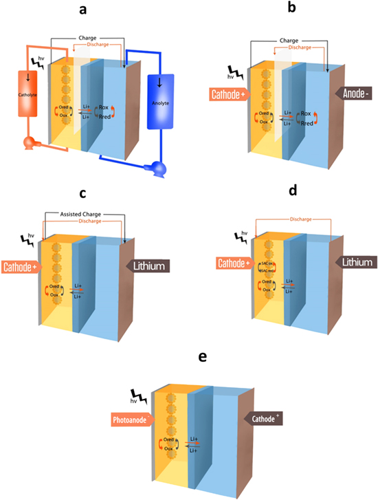
Figure 1. (a) photorechargeable three electrodes redox flow Li-ion battery; (b) photorechargeable three electrodes Li-ion battery; (c) photoassisted chargeable Li-metal battery; (d) Li-metal battery with a photo-oxidazable cathode and a sacrificial agent; (e) photochargeable battery composed by photoanode and a catholyte.
Download figure:
Standard image High-resolution imageTowards Photo-Rechargeable Li-Ion Batteries
A redox-flow based battery (see Fig. 1a) offers the possibility to create a future 100% photo-rechargeable Li-ion system, as shown in Figs. 2a–2c. For example Yan et al.14 designed a LiI//Li2WO4 redox flow battery using a TiO2/N719 dye photoanode and a LISICON permeable membrane. During photocharge reaction, the photogenerated electrons produced by N719 are injected into the titania band, and subsequently lithium ions are intercalated in Li2WO4 while iodide ions are oxidized at the photoanode. Under illumination, the battery reached 0.76 V within 2 min corresponding to the I− oxidation into I3− , while the battery presented a good capacity retention (over 90%). Based on the same concept, other promising solar rechargeable redox flow battery systems were proposed, e.g., iodide/anthraquinone-2,7-disulfonic acid (AQDS) by McCulloch et al.,15 bis((3-trimethylammonio)propyl)-ferrocene (BTMAP-Fc)/bis(3-trimethylammonio)propyl viologen tetrachloride by Li et al.,2 and hexacyanoferrate/AQDS by Wedege et al.16

Figure 2. (a) Schematics of the configuration and working mechanism of the solar rechargeable redox flow battery in dual-phase electrolytes. In the battery, Li2WO4 is used as the anode in an aqueous electrolyte (0.1 M Li2WO4 and 0.2 M LiClO4 in H2O), LiI is used as the cathode in an organic electrolyte (0.1 M LiI and 0.5 M TBP in propylene carbonate), and LISICON, a lithium-ion conducting glass ceramic film, is used as the membrane to separate the liquid anode/cathode-active species. A Pt/Ti mesh is used as the working electrode for the electrochemical reaction of two soluble anode/cathode-active species. (b) Reactions occurring during the photo-charge and discharge, (c) Potential profiles of the solar rechargeable redox flow battery with Li2WO4 as the anode (0.1 M Li2WO4 and 0.2 M LiClO4 in H2O), LiI as the cathode (0.1 M LiI and 0.5 M TBP in propylene carbonate) under photo-charge under 100 mW cm−2 irradiation and a flow rate of 0.05 mL min−1, and a current density of 0.075 mA cm−2 for discharging in the dark. Below: discharge capacities vs cycle number during ten cycles.11 (d) Schematic and (e) photo-charge and discharge of a redox solar battery.17
Download figure:
Standard image High-resolution imageWithout applying any external flow, a solar redox battery was proposed by Mahmoudzadeh et al.17 in 2016 (Figs. 2d–2e) using a three-electrode architecture. Specifically, an N719 dye/TiO2 couple promoted polysulfides reduction and iodide ions oxidation through a "charging" circuit, whereas the discharge was achieved by a loading electrode dipped in the same photoanode solution, allowing the triiodide anion to be reduced to iodide (see Fig. 1b).
To increase the energy density of the battery, some researchers used lithium metal anode in the same three-electrode cell architecture.18,19 A light source could reduce the charge voltage of a lithium–air battery20 (see Figs. 3a–3c): by using an N719/TiO2 couple and iodide as the redox mediator, the oxidation potential of Li2O2 was reduced from 3.4 V (with the redox mediator but without light) to 2.8 V (under light irradiation). In this device, the photoelectrode and the air electrode were separated. During discharge, this configuration operated as a typical lithium–air battery, using the difference in the potentials of the air and lithium metal electrodes. However, photo-assisted charge was achieved by applying a potential between the lithium electrode and the photo-electrode. This applied potential leaded to the formation of I3− species close to the photo-electrode, which reduced the Li2O2 discharge product of the air electrode.
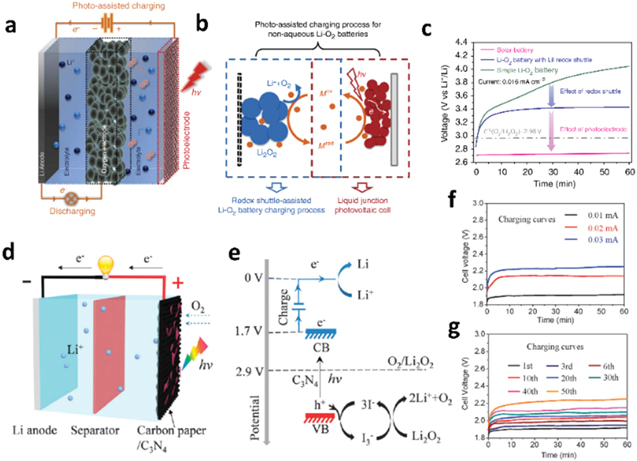
Figure 3. (a) Schematics of a three-electrode solar battery20: The solar battery comprises a Li anode, an oxygen electrode, and a photoelectrode. During charging, the photoelectrode and the Li anode are connected to the outside circuit, whereas during discharging, the oxygen electrode and the Li anode are connected to the outside circuit. (b) Proposed photoelectrochemical mechanism of the photo-assisted charging process: On charging under illumination, first, the redox shuttle in its reduced form (Mred) becomes oxidized to Mox on the photoelectrode, and subsequently diffuses to the Li2O2 particles that are deposited on the oxygen electrode. By oxidizing Li2O2 to O2 and Liþ, Mox is reduced back to Mred. (c) Charging curves of a simple Li–O2 battery with a LiI redox shuttle and the solar battery at a current density of 0.016 mA cm−2. (d) The photo-assisted rechargeable Li–O2 battery comprises a Li anode, a non-aqueous electrolyte combined with an I− ion redox mediator, and C3N4 grown on carbon paper as the oxygen electrode and photoelectrode.21 (e) In the photo-assisted charging process, the photoexcited electrons of g-C3N4 transfer to the anode to reduce Li+ to Li metal, and the generated photovoltage is utilized to compensate the required charging voltage. The photo-assisted charging voltage equals the energy difference between the redox potential of the Li+/Li couple and the conduction band of the photocatalyst (1.7 V). Concurrently, the I− ion redox mediator is oxidized to I3− by the photoexcited holes, and in turn, it oxidizes the discharge product, Li2O2; in the process, I3− is reduced back to I−.
Download figure:
Standard image High-resolution imageIt was also shown reported that a g-C3N4 photo-catalyst21 could further reduce the charge potential of Li-air battery to 1.9 V while applying 0.01 mA of charge (see Figs. 3d–3g). In this case, the g-C3N4 photocatalyst was deposited on the air electrode surface, which leads to a working two-electrode photo-assisted lithium–air battery (see Fig. 1c).
More recently, Liu et al.22 developed a solid flexible photo-assisted lithium–air battery, consisting of a pre-lithiated silicon anode, 5% mol LiTFSI in succinonitrile electrolyte, and a "ZnS@CNT"-coated carbon-paper or a carbon-textile photosensitized air electrode (Figs. 4a–4c). Even if the photo-sensitive "ZnS@CNT" was not a smooth layer of ZnS deposited on carbon nanotubes (CNTs) but rather a mixture of ZnS nanoparticles and CNTs, this battery presented a good capacity stability, with a light-assisted charge potential, which increased from 2.08 V to 2.2 V during at least 50 cycles at 0.026 mA cm−2 (Fig. 4d). The photo-sensitive coating reduced the charging voltage to approximately 2 V.
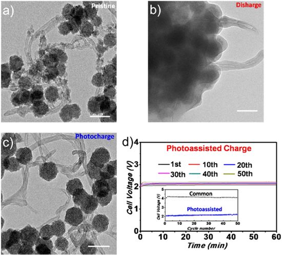
Figure 4. Transmission electron microscopy images of ZnS@CNT in a lithium-air battery of (a) pristine materials, (b) after the first discharge, and (c) after the first photo-assisted charge. The scale bar is 100 nm. (d) Different charge curves of the photo-assisted solid-state Li-ion–O2 battery at 0.026 mA cm−2 under illumination for 1 h and evolution of charge voltage between common and photo-assisted charges in inset.21
Download figure:
Standard image High-resolution imageIn 2015, Li et al.22 could charge LiFePO4 at 2.78 V, instead of the standard of ∼3.45/3.5 V, using a TiO2 photo-electrode and an iodide redox shuttle. Furthermore, the use of TiO2/perovskite layers between an FTO current collector and a dense carbon–sulfur cathode in a standard Li–S battery may result in a reduction in the charge time with respect to a standard power supply charge.23 In 2020 Guan et al. prepared In2S3@CNT on stainless steel foam as photocathode for photo assisted charged Li-CO2 batteries showing an increment of voltage discharge (from 2.73 V to 3.14 V) and decrement of voltage charge (from 3.86 V to 3.20 V) under light illumination. Monovalent In+ was identified as transient mediator of CO2 reduction at In2S3@CNT's surface: after its formation due to photoelectrons reduction, it an adduct of In3+ and oxalate was formed. Similarly Li et al.24 used silicon carbide—reduced graphene oxide SiC@RGo as photocatalyst in a conventional Li–CO2 cell reducing the voltage to 2.77 V during a discharge reaction.
Considering that any photo-catalyst is able to reduce alkaline metals to their elemental state, some studies in the literature reported the self-oxidation of cathode materials under light illumination (see architecture in Fig. 1d). For example, Li et al.25 oxidized polysulfide by reducing protons to H2 gas (water as sacrificial agent) using a CdS@Pt photocatalyst. Our group later photo-oxidized LiFePO4 by mixing it with dye N719, wherein oxidation occurred by the reduction of the carbonate electrolyte.26 In parallel, Nguyen et al.27 observed that both the charge and discharge capacity of a mesoporous titania thin film improved under light exposure (Figs. 5a–5b). Using cyclic voltammetry, the authors demonstrated that during the charge process, the photocarriers induced a highly rapid Li+ ion and/or e− transport across the nanoparticles allowed access to new sites, which could be electrochemically filled. Moreover, they observed bleaching of the reduced titania in their device under light exposure. Accordingly, they noted thattheir film occured a partial delthiation under light exposure. The authors showed that by cycling at C/7 under light illumination, the capacity of a titania film could exceed the theoretical value (Figs. 5a–5c). It appeared that photo-assisted delithiation can occur even during the discharge process. Furthermore, knowing that titania has photocatalytic properties, additional investigations are needed to determine the reactions of the extra electrons produced during the photo-assisted delithiation. A similar behavior was later observed for LiMn2O4.28 Photo-assisted delithiation seems to occur even in batteries using perovskite as both positive electrode and photosensitive material. Ahmad et al.29 reported self-charging activity with a two-dimensional organometallic perovskite under illumination for approximately ten cycles. However, the discharge capacity progressively decreased when the device was used between 2 V and 3 V vs Li+/Li0 potential windows. These stability problems may originate from the limited stability of organometallic perovskites, such as the three-dimensional ones, in addition to some electrolyte degradation. Moreover, using a graphene-coated glass, the authors attempted to cycle the device at a really low voltage (0.3 V vs Li+/Li0). After the third cycle, the device voltage could not exceed 1 V vs Li+/Li0. The authors demonstrated an irreversible degradation of their organometallic perovskite material by the Pb metal formation occurring below 1.4 V vs Li+/Li0. However, they hypothesized the possible existence of some photo-assisted delithiation due to the 2 LiI + 2 h+ → 2Li+ + I2 reaction. In addition Ren et al.30 studied the electrochemical properties of germanium selenide nanoparticles showing photo-response property during assisted-charge. After the formation of the solid electrolyte interphase, this material presented a high discharge capacity of approximately 500 mAh g−1 at a current of more than 2C (Figs. 5d–5e). Moreover, the authors studied the impact of visible light on the open circuit voltage (Voc) curves in both aqueous and organic solvents (Figs. 5f–5g). In both cases, electrode irradiation rapidly affects the open circuit voltage Voc, with a fast decrease in the aqueous solvent and an increase in the organic one. However, the high price of germanium and the low useful potential windows ([0 V;1.5 V] vs Li metal) may limit the interest in this material for mass production.

Figure 5. (a) Scanning electron micrography image of mesoporous TiO2. (b) Difference between the charge and discharge curves at 1C rate with and without illumination. The insets correspond to pictures of the TiO2 film in an almost fully charged state (bleach one) and discharged state (dark blue). (c) Difference between the charge and discharge curves at C/7 rate with and without illumination on titania electrode.23 (d) Different charge and discharge curves at 0.2 A g−1, and (e) Rate performance of GeSe electrodes mounted on coin cells vs lithium metal in 1 M LiPF6 in EC/DEC (30–70). OCV evolution of the GeSe electrode with and without light illumination (f) with a Pt counter electrode, aqueous solution of 0.5 mM Na2SO4, and a saturated calomel reference electrode, and (g) with a lithium metal counter electrode in 0.01 M LiClO4 in PC electrolyte.24
Download figure:
Standard image High-resolution imageAbout the architecture shown in Fig. 1e Wang et al.31 used WO3-CdS-TiO2 as photoanode: under illumination photoelectrons generated by CdS were able to reduce WO3 through TiO2 connection while I− was oxidized to I3− with a general operating voltage of around 0.6 V. The battery's cycling was not completely reversible due to CdS deterioration after the formation of SO42−—based side products through the formation of an elemental sulfur intermediate. WO3 was also used by Doukouzkis et al.32 in similar photoelectrochromic cell based occuring a lithium intercalation/de-intercalation reaction with a cobalt specie (Co(II)(bpy)3(PF6)2) as hole acceptor. The Co-redox shuttle showed higher recombination losses with respect to standard I−/I3− but the authors could limit it by depositing of a ZnS interlayer on working electrode.
Concerning the electrolyte, the impact of long term (up to 200 h) solar light under A.M. 1.5 G conditions (100 mW cm−2) on standard 1 M LiPF6 in EC/DEC was studied by Bouteau et al.33 The salt demonstrated good photostability with the formation of tiny amount of POF(OH)2 and POF2(OH) due to LiPF6 hydrolysis (Figs. 6a–6c). However, by using a combination of UV–vis and Raman spectroscopic techniques a local reorganization between the ions and solvent was detected, showing a yellowish coloration of the electrolyte (Figs. 6d–6f). Solar light irradiation promotes the bonding of the solvent (both ethylene and dietylene carbonate) with the lithium ions. Even if the ionic conductivity is slightly improved by the light irradiation, further tests of full battery systems have to be performed to precisely verify the stability of common battery electrolytes in photo-assisted battery devices. In addition, the photo-stability of the electrolyte is strongly dependent on the atmosphere: after photo-oxidation of LiFePO4 by dye N719,27 the carbonate electrolyte can be reduced by photo-generated electrons and/or react with photo-reduced O2. Therefore the choice of a stable electrolyte under light illumination in combination with an inert atmosphere is a crucial step to design a stable photo-chargeable battery. Ether-based electrolyte results to be stable during photocharge: Lei at al. proposed a quasi-solid (gel) polyethylene oxide:LiTFSI electrolyte in three electrodes system by using TiO2-dye as photcalayst, I−/I3− as catholyte,and antraquinone as anolyte. The authors were able to cycle the photbattery for 10 cycles with modest discharge capacities (around 10 mAh g−1).

Figure 6. (a) 1H, (b) 19F, and (c) 31P NMR spectra of 1 M LiPF6 EC/DMC 1/1 weight ratio before and after 100 and 200 h. (d) UV–Visible absorption spectra of 1 M LiPF6 EC/DMC electrolyte when fresh (black curve) and after 100 h (red curve) and 200 h (blue curve) of illumination. Photograph of electrolyte when fresh and after 200 h of irradiation is in the inset. Evolution of the Raman spectra of illuminated 1 M LiPF6 EC/DMC as a function of continuous illumination time in (e) the vibration mode region (700–760 cm−1) and (f) stretching mode region (870–950 cm−1). All the light irradiations are performed under A.M. 1.5 G conditions. This study was performed by Bouteau et al.26
Download figure:
Standard image High-resolution image
Discussion
The principles of photo-rechargeable technology are evolving through different approaches; however, their applications still remain fare from commercialization. Future research should address the following challenges:
- (i)In a three electrodes configuration with (Fig. 1a) and without (Fig. 1b) an anolyte and a catholyte reservoir) new redox couples need to be explored, in order to increase the battery voltage. In addition, new chemistries must be examined to reduce the recombination events. This architecture will be considered for stationary applications with low energy density.
- (ii)In photoassisted Li-metal anode charging (Fig. 1c) and photo-oxidizing cathode (Fig. 1d) battery-types new different compositions must be taken in account by mixing active nanomaterials (e.g nano LiFePO4, nano LiCoO2, nano WO3, nano Li2O2) with photocatalysts (e.g perovskites, C3N4) to increase the reactive surface, and thus, the recombination efficiency. It is also possible to use several quantum dot types with chalcogenide compositions (PbS, CuInS2, metal tellurides) exploring new core–shell structures as well. It will also be possible to graft various functional groups on a nanoparticle surface that may control the lithium ions insertion/deinsertion process, particularly in photo-assisted charging batteries (Fig. 1c).
- (iii)Currently, no semiconductor/photocatalysts can promote the reduction of lithium ions because any semiconductor has a conduction band with a lower potential level than any alkaline anodic potential. Actually the use of metallic lithium is limited to architectures that involve a sacrificial agent following an irreversible reactions (electrolyte decomposition—Fig. 1d) Moreover their photo-degradation and/or side reactions with electrolytes must be considered to increase the cycling life of the final battery. Future researches may be directed toward easy and low-cost sacrificial agents without the formation of irrevirsible side products.
- (iv)The use of photoanode (Fig. 1e) combined with a catholyte could exhibit a full photochaargeable behavior. For Li-ion-battery applications the active material loading must be strongly increased although severe self-discharge reactions are possibly present: one has to tackle not only the self-discharge of light-separated electrons and holes through re-combination and quenching by impurities/heterogeneities, but also the usual self-discharge of the battery mode that takes place by parasitic electrochemical reactions on open-circuit.
- (v)The photostability of the liquid (or gel/solid) electrolyte needs to be optimized to avoid any possible side reactions that limit battery cycling life. The formation of radical species may catalyze a polymerization reaction and the formation of insulating species, which influence charge transfer. In addition, the photostability of an electrolyte needs to be extended to its photo-ambient-stability: degradation occurs when the electrolyte is under light exposure in a particular atmosphere, such as ambient air. An electrolyte decomposes more rapidly in the presence of oxygen than in an inert atmosphere such as argon.
- (vi)New polymers that are able to convert and store the solar energy in one single molecule may be designed and synthesized; the aim of the idea is to reduce the occurrence of any possible side reactions between a semiconductor and an active material by using a single active materials toward photons and toward lithium ions.
Conclusions
The combination of solar and Li-ion battery technologies in a single device is still challenging because of recombination and decomposition reactions. In this review article we resumed several approaches focusing on the different basic mechanism of photocharge/discharge. We considered the following Li-ion photochargeable battery classes: (a) redox flow battery, (b) three electrodes based battery, (c) photo-assisted charging two electrodes battery, (d) two electrode battery with a Li-metal anode and a sacrificial agent, and (e) two electrodes battery composed by a photoanode and a catholyte reducible at a current collector surface when the external circuit is closed. Moreover, we presented the possible side reactions occurred to photocatalyst and electrolyte under light exposure in presence of oxygen. It would be desirable to compare the energy densities achieved by various types of photo-batteries. However, for reliable and valid such comparisons, it is essential to achieve first electrochemical/photochemical stability in these systems over a number of reproducible cycles, perhaps at least 100 cycles: this work is however still in progress. Finally we presented some potential opportunities for improved performance, including new materials and architectures.
Acknowledgments
The authors want to thank Professor Federico Rosei of INRS (Canada), Dr. Chisu Kim and Eloise Leroux of Hydro-Quebec for useful discussions.