
Abstract
Here we report a small, slow and in situ sensing (3S) nail penetration test method to understand Li-ion cell internal short circuit (ISC) and thermal runaway. The method not only keeps conventional nail penetration's advantage of simple implementation, but also enhances its relevance to field failures and enables detailed in situ diagnosis. It was applied to 3-Ah pouch cells and revealed insights that could not be captured by conventional methods. Most interestingly, multiple in situ temperature peaks were observed during a period of over 100 s before thermal runaway. These initial peaks exceeded safety limit but the temperature rapidly decreased after each peak instead of causing immediate thermal runaway. Further investigation suggested that the initial temperature peaks occurred when nail tip reached aluminum foil current collector to form a low resistance ISC between anode and aluminum foil. The rapid temperature decrease after each peak can be attributed to sudden drop of ISC current, which can be further attributed to rupture of aluminum foil and increase of contact resistance. The findings show that 3S nail penetration test can separate processes of ISC from thermal runaway and provide details of ISC at the level of individual electrode and current collector.
Export citation and abstract BibTeX RIS

This is an open access article distributed under the terms of the Creative Commons Attribution 4.0 License (CC BY, http://creativecommons.org/licenses/by/4.0/), which permits unrestricted reuse of the work in any medium, provided the original work is properly cited.
Thermal runaway is a critical safety challenge for widely used Li-ion batteries.1–3 It has resulted in catastrophic field failures involving consumer electronics,4–6 electric vehicles,1,2 aerospace,7 stationary energy storage systems8,9 and various other applications.10 Several high-profile thermal runaway incidents have been found due to internal short circuit (ISC) of individual Li-ion cells.4–7 The ISC was further attributed to manufacturing defects such as microscopic metal particle contamination, damaged electrode, and tab welding defects.4–7 Such ISC-caused thermal runaway is dangerous because it is difficult to detect, and cannot be predicted or prevented by battery management systems.11,12
Nail penetration has been widely used to trigger ISC for safety evaluation since early commercialization of Li-ion cells by Sony13,14 and is required in several international safety standards as reviewed in Ref. 15. But there are three challenges in creating and understanding field-failure-relevant ISC by conventional nail penetration. First, typically used metal nails have large size (diameter from 3 mm to 20 mm) with large thermal mass and low resistance, which could significantly influence mechanical and thermal behaviors of tested Li-ion cells.16,17 Second, nail penetration is typically done at relatively high speed, 10–40 mm s−1 or even above 80 mm s−1,15,18,19 which makes it difficult to control penetration depth with electrode level accuracy. A Li-ion cell is either fully penetrated or partially penetrated with unknown layers of electrodes in short circuit. But in field failure, ISC would be small size and isolated.20 Third, heat generation during ISC is highly localized with very non-uniform temperature distribution.12 Cell surface temperature as conventionally measured would be significantly different from temperature at ISC spot,17 thus not being able to accurately characterize ISC or thermal runaway behaviors.
Alternative methods have been developed to create ISC that are more relevant to field failures by embedding triggering devices,11,21 such as nickel particle,22 low melting point metal or metal alloy defect,23 wax based device,24 and shape memory alloy based device.25 These methods enable precise control of ISC location but require sophisticated modification of testing cells. Maleki and Howard20 used small nails (4.0 mm × 1.5 mm × 1.5 mm) to trigger ISC, which could significantly reduce the influence of nail on mechanical and thermal behaviors of Li-ion cells. But the penetration depth was 2–2.5 mm deep into testing cell, suggesting multiple layers of ISC, and penetration speed was not reported. Yokoshima et al.26 also investigated ISC and thermal runaway by using a small nail of 1 mm diameter equipped with a high speed X-ray scanner. Detailed layer-by-layer ISC processes were observed, but the cells were fully penetrated in a fraction of second with nail speed of 10 mm s−1 and temperatures were only measured on cell surface and inner case.
Great efforts have been also made in monitoring local temperature near ISC spot by using nail with embedded temperature sensors.17,27–29 The local temperatures near ISC spot were indeed obviously higher than surface temperatures, confirming the critical importance of in situ sensing in understanding ISC and thermal runaway behaviors. Moreover, Poramapojana28 and Tanim et al.29 measured temperatures at different locations in the nails and the results suggested that embedded temperature sensors should be kept as close to ISC spot as possible for accurate measurement. But in these reports the nails were big (3.2 mm and above) and penetration was fast (10 mm s−1 and above).17,27–29 According to the work by Finegan et al.17 that combined in situ temperature sensing and high-speed X-ray imaging, penetration with a big nail could cause significant variation of failure mechanisms and severity of thermal runaway.
To keep nail penetration testing's advantage of simple implementation, while making it closely relevant to field-failure ISC and enabling accurate understanding of thermal runaway behaviors, here we propose a small, slow and in situ sensing (3S) nail penetration testing method. As schematically shown in Fig. 1a, in this method the nail is small (diameter ∼ 1 mm), significantly reducing influences of nail on mechanical and thermal behaviors of Li-ion cells. Penetration is done very slowly (below 0.1 mm s−1), enabling precise diagnosis and control of penetration depth. A micro temperature sensor is embedded in the nail tip as inspired by previous work,17,27–29 enabling accurate in situ sensing of temperature at ISC location. In addition to cell voltage, the voltage between positive tab and nail (V+) and voltage between negative tab and nail (V−) are measured as inspired by a previous report,30 allowing real time detection of when the nail tips touches the first conductive layer (electrode or current collector).

Figure 1. (a) Schematic of small, slow and in situ sensing (3S) nail penetration of a Li-ion cell; (b) Picture of a prototype small, in situ sensing nail.
Download figure:
Standard image High-resolution imageWe first applied the 3S nail penetration testing method to 3-Ah pouch format Li-on cells. The results are compared with those by conventional nail penetration testing using a 3 mm nail at speed of 40 mm s−1. The 3S nail penetration provided much more interesting details of ISC and thermal runaway than conventional nail penetration. To interpret the interesting results, we then applied the 3S nail penetration to two single-unit cells, one 3-cell module, one single layer cathode coated on aluminum foil, and one dummy cell. The dummy cell was also characterized by X-ray microscopic imaging. Based on findings and discussions, we proposed a mechanism to understand the ISC and thermal runaway behaviors of Li-ion cells during 3S nail penetration. Last, implications for enhanced Li-ion cell safety design and ISC testing were discussed.
Experimental
Fabrication of prototype small in situ sensing nails
Stainless steel syringe needles with outer diameter of 1.27 mm (18 G, Becton Dikinson) were used to make prototype small, in situ sensing nails. A K type micro thermocouple with external diameter of 0.5 mm (TJC36-CASS-020U-6, Omega Engineering) was inserted into a needle with the thermocouple tip near the needle tip. Steel reinforced epoxy (J-B WeldTM) was used to fill the gap between needle wall and thermocouple to keep the thermocouple tip fixed and strengthen the nail. Figure 1b shows picture of a prototype nail. Note that the needle size was chosen to match the thermocouple size for quick fabrication of small yet strong enough prototype nails for the cells in this study. Thermocouple of smaller size would be desired for faster response. Nail size should be optimized according to thermocouple size, strength requirement and resistance requirement.
Experimental Li-ion cells and electrodes
Two types of commercially available Li-ion pouch cells were used. One type has a nominal capacity of 3 Ah (LP 6050100, Tenergy) and the other has a nominal capacity of 20 mAh (PGEB0052081, Powerstream Technology). Each 3-Ah cell has a dimension of 6 mm × 51 mm × 102.5 mm (not including tabs) with 15 layers of double side coated anode sheets and 14 layers of double side coated cathode sheets. Each 20-mAh cell has a dimension of 0.5 mm × 20.0 mm × 81.0 mm, with only one layer of single side coated anode and one layer of single side coated cathode. These 20-mAh cells are referred as single-unit cells.
A single layer cathode coated on aluminum foil (LiFun Tech) was used for characterization of resistance changed during nail penetration. The cathode coating is 0.055 mm thick and aluminum foil is 0.015 mm thick.
A dummy cell without electrolyte (MTI Corp) was used for X-ray microscopic imaging after nail penetration. The cell has a dimension of 125 mm × 63 mm × 7.6 mm, with 22 layers of double side coated anode sheets and 21 layers of double side coated cathode sheets.
Experimental system and test protocol
As listed in Table I, seven tests were done. Test 1 was conventional nail penetration of 3-Ah cell using a big nail (3 mm diameter) at high speed (40 mm s−1). Test 2 was 3S nail penetration of 3-Ah cell. Test 3 and Test 4 were 3S nail penetration of 20-mAh cells. As schematically shown in Figs. 2a and 2b, the penetration was from copper foil to aluminum foil in Test 3 and opposite in Test 4. Test 5 was 3S nail penetration of a module. As schematically shown in Fig. 2c, the module consisted of three 3-Ah cells connected in parallel. Test 6 was penetration of a single cathode coated on aluminum foil. In this test the resistance between nail and aluminum foil was measured using a four-point probe method,31 as schematically shown in Fig. 2d. Test 7 was 3S penetration of a dummy cell that was later examined by X-ray microscopic imaging.
Table I. List of tests performed in this study.
| Test | Cell/Electrode information | Nail diameter | Penetration speed | Note |
|---|---|---|---|---|
| 1 | 3-Ah cell | 3.0 mm | 40 mm s−1 | Full penetration |
| 2 | 3-Ah cell | 1.27 mm | ∼0.02 mm s−1 | Full penetration |
| 3 | 20-mAh single-unit cell | 1.27 mm | ∼0.02 mm s−1 | Penetration from Cu to Al |
| 4 | 20-mAh single-unit cell | 1.27 mm | ∼0.02 mm s−1 | Penetration from Al to Cu |
| 5 | 3-cell module made of 3-Ah cells | 1.27 mm | ∼0.02 mm s−1 | Full penetration |
| 6 | Cathode on Al foil | 1.27 mm | ∼0.02 mm s−1 | From cathode to Al |
| 7 | 7-Ah dummy cell | 1.27 mm | ∼0.02 mm s−1 | Partial penetration |

Figure 2. Schematics of 3S nail penetration of (a) single-unit cell from Cu to Al, (b) single-unit cell from Al to Cu, (c) 3-cell module, (d) single layer cathode coated on Al foil.
Download figure:
Standard image High-resolution imageAll nail penetration tests were conducted inside a hydraulic driven battery crushing & nail penetration machine (MSK-TE905, MTI Corp). The machine has a safety chamber and ventilation for handling of cell thermal runaway. The machine was specified for penetration speed from 1 mm s−1 to 50 mm s−1, but through fine-tuning a speed of ∼0.02 mm s−1 was achieved in this study. Note that the nail penetration speed should be optimized according to test needs. A nail penetration machine that could achieve slower and more stable penetration speed, e.g. 0.01 mm s−1 or slower, would be desired to allow optimization of penetration speed. For tests 1 to 5, each Li-ion cell or module was fully charged by a battery tester (LBT21084, Arbin) at room temperature using a constant current constant voltage protocol (1C, 4.2 V max, C/20 cutoff current) before penetration testing. In single cell testing, cell surface temperature was measured by placing a thermocouple on cell top surface 10 mm from the nail penetration location. Shunt resistors (SHD1-100C075DE, Ohmite) were used to measure current in test 5 and test 6. For test 6, a DC power supply (Model EF, EPSCO) was used to provide a constant voltage. During nail penetration testing, all data were recorded by a data acquisition unit (34980 A, Keysight). The data recording rate was 6 Hz in test 5 and 10 Hz in all other tests. The slower rate in test 5 was due to limitation of the data acquisition unit when more channels were used.
X-ray microscopic imaging
X-ray microscopic imaging was used to obtain information on internal structure change of Li-ion cell due to nail penetration. A dummy cell without electrolyte was penetrated and then sent to Carl Zeiss Microscopy for imaging using Xradia 620 Versa 3D X-ray Microscopy. The unique architecture of the X-ray microscope allows for high resolution imaging at large distances. This enabled the full dummy cell to be imaged without further cutting or manipulation. Imaging was performed using 0.4× and 4× objectives with 160 kV acceleration energy, and proprietary HE6 filter to reduce beam hardening effects. A total of 1601 projections was used for both sets of tomographies over a range of 202 and 184 degrees, with High Aspect Ratio Tomography (HART) collection. These settings allowed for imaging at the center of the cell near the nail tip with resolution of 0.025 mm and 0.0025 mm, respectively.
Results and Discussion
Conventional nail penetration and 3S nail penetration of 3-Ah cells
Figures 3a–3c show the results of cell voltage, tab voltage and cell temperature in conventional nail penetration testing using a 3 mm nail at speed of 40 mm s−1. Note that in this study the time 0 s is defined as the moment when the negative tab voltage (V−) becomes 0 V, indicating that the nail just penetrates through cell pouch and touches the first conductive layer (anode). It can be seen that the cell went into thermal runaway very quickly as indicated by rapid drop of cell voltage and increase of cell surface temperature. With the cell thickness of 6 mm and the penetration speed of 40 mm s−1, the cell was fully penetrated in less than 0.2 s. A closer check of the details, as shown in the figure inserts, shows that cell voltage dropped to 0.5 V in 2 s and 0.1 V in 5 s. The surface temperature only increased slightly in 2 s and reached ∼150 °C in 5 s. It took nearly 20 s to reach maximum temperature. Apparently, the fast nail penetration and slow surface temperature response make it difficult to obtain insightful information for understanding of ISC and thermal runaway.

Figure 3. Conventional nail penetration of a 3-Ah Li-ion cell. (a) Cell voltage; (b) Tab voltage; (c) Cell temperature.
Download figure:
Standard image High-resolution imageFigures 4a–4c show the results of 3S nail penetration testing with the prototype nail at speed of ∼0.02 mm s−1. The cell also went into thermal runaway in this test, but it took more than 100 s for the cell to go to thermal runaway and many details were obtained. The in situ sensed nail tip temperature reached a maximum of over 800 °C during thermal runaway while the cell surface temperature only reached ∼400 °C. More importantly, the in situ sensing clearly captured three peaks before thermal runaway while there was no obvious response in surface temperature until thermal runaway. Such dramatic difference confirmed that in situ temperature sensing can indicate thermal runaway severity more accurately and detect ISC earlier than surface temperature sensing. It is also interesting to note that cell voltage only decreased very slightly when the nail tip temperature peaks occurred before thermal runaway.

Figure 4. 3S nail penetration of a 3-Ah Li-ion cell. (a) Cell voltage; (b) Tab voltage; (c) Nail tip temperature and cell surface temperature.
Download figure:
Standard image High-resolution imageFigure 4c shows that the nail tip temperature quickly dropped after each of the three initial peaks at 18 s, 48 s and 104 s, respectively. The second peak and third peak reached above 300 °C and 500 °C, significantly higher than typical thermal runaway onset temperature,32–34 but surprisingly they did not lead to immediate thermal runaway.
Several questions arose from the results of 3S nail penetration testing above. Why were there several nail tip temperature peaks before thermal runaway? Why was the temperature dropping after each peak instead of rising to thermal runaway? Why did the nail tip temperature increase and drop sharply? To answer these questions, several hypotheses were developed and tested below.
Hypothesis on nail tip temperature peaks and tests of single-unit cells
Santhanagopalan et al.35 numerically modeled four possible ISC scenarios in a Li-ion cell, including Cu-Al short, Cu-Cathode short, Al-Anode short, and Cathode-Anode short. They found that the Al-Anode short scenario would cause significantly faster local heat generation and temperature rise than other scenarios, which was also experimentally confirmed by Keyser et al.36 The 3-Ah cell used this study has 15 layers of copper foil with double side coated anode and 14 layers of aluminum foil with double side coated cathode. There was one layer of separator between every anode and cathode. During nail penetration, the cathode would be firstly in short with copper and anode. But due to the low electric conductivity of cathode materials, the heat generation and temperature rise would be small. When the nail tip reached aluminum foil which is highly conductive, the heat generation and temperature rise would become dramatically faster. Therefore, it can be hypothesized that the initial in situ temperature peaks in Fig. 4c occurred when the nail contacted aluminum foil and caused low resistance ISC between anode and aluminum. A closer examination of the first temperature peak, shown in Fig. 5, supports this hypothesis. There was a small increase in nail tip temperature between 15.4 s and 17.7 s. The corresponding voltage drops are also consistent with the hypothesis.

Figure 5. Details of the first nail tip temperature peak and corresponding voltage drop during 3S nail penetration of a 3-Ah cell.
Download figure:
Standard image High-resolution imageThe hypothesis is further supported by 3S nail penetration of 20-mAh single-unit cells. According to the hypothesis, if the penetration is from copper foil to aluminum foil, the cathode would be first in short with anode and copper foil, causing a slow temperature rise. Then the aluminum foil would be in short with anode, causing a faster temperature rise after the initial slow rise. In comparison, if the penetration is from aluminum foil to copper foil, the first ISC would involve anode and aluminum so the nail tip temperature would suddenly rise without initial slow rise. These expected different behaviors were indeed observed as shown in Figs. 6 and 7. It can be seen from Fig. 6 that cell voltage and temperatures remained stable for 9.4 s, indicating there was no ISC during this period. From 9.4 s to 12.9 s, the nail tip temperature started increasing slowly while the cell voltage started decreasing slowly, indicating cathode was in short with copper and anode. After 12.9 s, nail tip temperature began to increase quickly while cell voltage abruptly dropped, indicating aluminum foil was in short with anode. Figure 7 shows results of penetration from aluminum foil to copper foil. As expected, the local temperature increased abruptly at 15.1 s without initial slow increase and cell voltage dropped immediately without initial slow decrease, indicating ISC between anode and aluminum.

Figure 6. Temperatures and cell voltage during 3S nail penetration from Cu foil to Al foil of a 20-mAh single-unit cell.
Download figure:
Standard image High-resolution image
Figure 7. Temperatures and cell voltage during 3S nail penetration from Al foil to Cu foil of a 20-mAh single-unit cell.
Download figure:
Standard image High-resolution imageHypothesis on nail tip temperature drop and test of 3-cell module
Considering that the nail tip temperature quickly dropped after each initial peak in Fig. 4c, the local heat generation must be dramatically reduced. Local heat generation greatly depends on ISC current, so it is hypothesized that the nail tip temperature dropped due to abrupt decrease of ISC current. The 3-cell module was tested to validate this hypothesis. The module consists of three single cells connected in parallel as shown schematically in Fig. 2c. Ideally, the current distribution of each electrode layer in the single cell should be measured to determine variation of ISC current and test the hypothesis. But such measurement would require fabrication of special segmented cells,37,38 which is out of the scope of this work and will be done in future work. Considering that the electrode layers were connected in parallel in the single cell, their current distribution behaviors could be mimicked and indirectly characterized by current distribution behaviors of the 3-cell module.
Figure 8 shows the cell voltage, nail tip temperature and individual cell current during nail penetration of the 3-cell module. The top cell went into thermal runaway at ∼100 s as indicated by nail tip temperature peak above 800 °C. Before thermal runaway of the top cell, multiple nail tip temperature peaks occurred while surface temperature did not show obvious change. These behaviors were similar to those of single cell test. The magnitude of temperature peaks was smaller in this module test than that in the single cell test, which can be attributed to slower data acquisition frequency in this test as explained earlier. Some surface temperature data were missing due to use of a T type thermocouple which had a range upper limit of 400 °C.

Figure 8. 3S nail penetration of a 3-cell module. (a) Cell voltage; (b) Nail tip temperature and top cell surface temperature; (c) Cell currents.
Download figure:
Standard image High-resolution imageA closer check of the individual cell currents showed current peaks corresponding to the temperature peaks. Between these peaks, the currents were nearly zero. This finding suggests that ISC current was significant only for a very short pulse. It supports the hypothesis that ISC current rapidly increases when aluminum foil is in short with anode and that the current abruptly drops after a short peak. Such a short pulse of current would cause a pulse heat generation, which would further cause a local temperature peak.
It is interesting to note that the module voltage drops very slightly, less than 30 mV, at the nail tip temperature peaks before thermal runaway of the top cell. The module voltage almost fully recovered after the top cell went into thermal runaway. It suggests that ISC is much more difficult to be detected by voltage drop for a large Li-ion cell or module than that for a small cell.
Hypothesis on ISC resistance change and test of single layer cathode on aluminum foil
The results and discussion above suggest that the dramatic decrease of nail tip temperature after each initial can be attributed to the abrupt drop of ISC current. Previous modeling results by Zhao et al.16 showed that ISC resistance significantly influences ISC current. It is hypothesized that the ISC current abruptly dropped due to dramatic increase of ISC resistance. To verify this hypothesis, a single layer cathode coated on aluminum foil was tested using the 3S nail penetration. The resistance was measured using a four probe method as schematically shown in Fig. 2d. A similar method has been used by Chen et al.31 recently to characterize static resistance after electrode and current collector foil were penetrated by a nail. Here the method is used to characterize transient variation of resistance during nail penetration of a cathode coated on aluminum foil. The results are shown in Fig. 9, including measured voltage drop across electrode and aluminum foil, current flowing through the nail and estimated short circuit resistance. It can be seen that the resistance was initially very high and gradually decreased as nail penetrated deeper into the cathode. Then the resistance abruptly dropped by several orders of magnitude, suggesting the nail touched the aluminum foil. But very quickly the resistance recovered to a level as high as before the sudden drop. A visual check of the cathode electrode and aluminum foil, as shown in Fig. 9c insert, suggested that the aluminum foil ruptured. Aluminum rupture would cause significant contact resistance increase between the aluminum foil and the nail. These results support the hypothesis that ISC current abruptly increased when nail tip touched aluminum foil and then quickly dropped due to dramatic increase of ISC resistance. It also suggests that the dramatic increase of ISC resistance can be attributed to rupture of aluminum foil. It took a long time for the cathode to rupture, which could be due to deformation of the single layer cathode.

Figure 9. Variation of (a) voltage, (b) current and (c) estimated resistance during test of a single layer cathode coated on aluminum foil (insert picture shows ruptured cathode and aluminum foil).
Download figure:
Standard image High-resolution imageTest and X-ray microscopic imaging of dummy cell
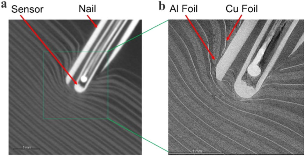
X-ray microscopic imaging was used to confirm rupture of aluminum foil in a full cell after nail penetration. Due to safety concern, a dummy cell without electrolyte (MTI Corp.) was partially penetrated and then sent to Carl Zeiss Microscopy for X-ray imaging using ZEISS Xradia 620 Versa 3D X-ray Microscopy. Figures 10a and 10b show images near the nail tip with a resolution of 0.025 mm and 0.0025 mm, respectively. It can be seen that a few layers of electrodes and current collector foils were penetrated. The rupture of aluminum foil can be indeed observed from the small gap between the foil and the nail, supporting the hypothesis that aluminum foil ruptured during nail penetration and caused rapid increase of contact resistance. The X-ray imaging also shows that mechanical deformation of the electrodes was limited to a size comparable to the nail diameter, suggesting the necessity of using a small diameter nail.

Figure 10. X-ray microscopic imaging of a dummy Li-ion cell after nail penetration. (a) Resolution of 0.025 mm; (b) Resolution of 0.0025 mm.
Download figure:
Standard image High-resolution imageProposed mechanism of ISC during nail penetration
Based on the results and discussion above, a mechanism is proposed to explain the behaviors of ISC and nail tip temperature during 3S nail penetration of the 3-Ah cell. The mechanism is schematically shown in Fig. 11. After the nail penetrates the first layer of copper foil, anode and separator, ISC would be formed and its development can be divided into three stages. In stage 1, the nail tip contacts cathode so that cathode is in short with copper foil and anode. High resistance of cathode material would limit the ISC current to a low level. Correspondingly, the increase of heat generation and local temperature are slow. In stage 2, the nail tip contacts aluminum foil so that aluminum foil is in short with copper foil and anode. The aluminum foil resistance is much lower than cathode materials. The contact resistance between aluminum foil and nail is also very small due to tight contact. The overall ISC resistance would be several orders of magnitude smaller than that in stage 2, leading to a very high ISC current flowing through the nail and aluminum foil around the nail tip. The high current causes rapid local heat generation and temperature rise. Due to the small thickness of aluminum foil, only 0.02 mm, it would be quickly penetrated by the nail and ruptured. The ISC would then enter stage 3. In this stage, the contact resistance between aluminum foil and nail becomes so large that the overall ISC resistance would be comparable to stage 1. In response, the ISC current and local heat generation would significantly drop. The local temperature at nail tip would also rapidly drop due to heat transfer to nail body and adjacent cell materials. As the nail penetrates deeper into the cell, similar processes would repeat, causing another large yet temporary ISC current and local temperature peak, as can be seen from Fig. 4c. Combined with thermal energy stored during previous ISC pulses, the local heat generation and temperature peak would become increasingly higher, eventually high enough to cause thermal runaway.

Figure 11. Proposed mechanisms of ISC process during 3S nail penetration.
Download figure:
Standard image High-resolution image
Implication for safer Li-ion cell development
This study implies two additional promising approaches of enhancing Li-ion cell safety that are less explored than other approaches such as solid-state electrolytes,39 fire suppression and rapid cooling.2 The first approach is developing current collectors that can rapidly and easily rupture upon mechanical impact or local high temperature, so that the contact resistance increase dramatically to limit ISC current and heat generation. This is especially important for aluminum foil. Several recent reports based on modification of current collector have shown promising results, such as current collector with surface notches,40 electrode partition41 and metalized plastic current collector.42,43 The second approach is increasing anode materials resistance. Due to the high resistance of cathode, the local heat generation and temperature rise are very small when cathode is in short with copper foil and anode. With typical composition of graphite, carbon black and binder, the anode resistance is much lower than cathode. If the anode resistance is increased to be comparable with cathode resistance, the local heat generation and temperature rise could be effectively limited in all scenarios of ISC. Anode resistance may be tailored by modifying electrode composition44,45 or microstructures. A study using coin cell by Le et al.46 showed that heat generation during nail penetration could be reduced nearly 50% by modifying carbon black in anode. Further studies are needed in both approaches.
Implication for nail penetration testing and other ISC triggering methods
This study has three implications for nail penetration testing and other ISC triggering methods. First, not all ISC would cause thermal runaway. If the nail penetration is terminated too early, for example, based on the first drop of cell voltage or tab voltage, it could create a false impression of battery safety. The effects of penetration depth should be carefully considered and controlled in nail penetration testing. Second, the deformation of Li-ion cell internal structure greatly depends on the size of nail according to the X-ray microscopic imaging. It is beneficial to keep the size of nail as small as possible to reduce the influence of nail on internal structure change. Third, in situ temperature sensing is much more accurate and sensitive than surface temperature sensing. It would be useful to in situ monitor ISC temperature, whether the ISC is triggered by nail penetration or other methods.
Future work
The results and discussions above demonstrated advantages of 3S nail penetration in understanding ISC of Li-ion cells. Further efforts are worthy in the following aspects. First, optimization of small nails with embedded micro temperature sensors. As shown in the X-ray image of a prototype nail, there are clear gaps between nail tube, thermocouple sheath and thermocouple. The gap was filled with non-conductive epoxy. By optimizing nail and temperature sensor, the gap can be reduced to make nail stronger and temperature sensor more sensitive. The nails will be also made of various materials, including both metallic and non-metallic, to simulate ISC scenarios with different resistance. The nails should be also optimized according to different types of Li-ion cells, such as cylindrical and prismatic cells with hard casing. Second, integration of 3S nail penetration with other in situ diagnostic techniques, such as in situ X-ray imaging, gas analysis, and current distribution measurement. By visualizing change of internal structure during small nail penetration with X-ray imaging, analyzing composition of gas generation, and measuring current distribution in a single cell, additional insights can be obtained to complement the temperature and voltage signals for a comprehensive understanding of ISC and thermal runaway behaviors. Third, integration of 3S nail penetration with quantitative analysis. Not all ISC cause thermal runaway. 3S nail penetration enables accurate control of penetration depth and in situ sensing, which can be further integrated with quantitative analysis to determine critical conditions of ISC that would lead to thermal runaway. Fourth, development of Li-ion cells with different cell compositions and structures for enhanced safety. As discussed above, electrode and current collector structure and composition could significantly influence ISC resistance. Detailed investigation with 3S nail penetration could facilitate development of fundamentally safer Li-ion cells. Fifth, systematic investigation of Li-ion cells with different types, materials and configurations. These factors could significantly influence ISC and thermal runaway behaviors, thus a systematic investigation by 3S nail penetration could benefit optimization of Li-ion cell designs.
Conclusions
We developed a small, slow and in situ sensing nail penetration method for understanding ISC and thermal runaway behaviors of Li-ion cells. By applying the method to 3-Ah pouch cells, we observed multiple peaks of local temperature at ISC spot before thermal runaway, which could not be captured in conventional nail penetration testing. We also observed that the local temperature rapidly dropped after each peak. Through further investigation of 3S nail penetration with single-unit cells, a 3-cell module, a single layer cathode and a dummy cell, as well as X-ray microscopic imaging of the dummy cell, we proposed a mechanism to interpret the interesting temperature behaviors and ISC processes. The temperature peaks can be attributed to contact of nail tip with aluminum foil current collector, which created a low resistance ISC between anode and aluminum foil. This low resistance ISC induces high ISC current and rapid heat generation, leading to abrupt local temperature rise. The rapid temperature drop after each peak can be attributed to temporary stop of internal current, which can be further attributed to rupture of aluminum foil and dramatic increase of contact resistance. The findings in this study suggest that the 3S nail penetration method can separate ISC from thermal runaway and provides details of ISC to the level of individual electrode layer and current collector foil. The findings also suggest promising approaches to enhancing Li-ion cell safety through significantly increasing contact resistance or anode material resistance during ISC.
Acknowledgments
G. Zhang acknowledges helpful discussions with many colleagues throughout the course of this work, especially Dr. Judy Jeevarajan at Underwriters Laboratories, Dr. Thomas P. Barrera at LIB-X Consulting, Dr. Boryann Liaw at Idaho National Laboratory, and Dr. George Nelson and Dr. Keith Hollingsworth at The University of Alabama in Huntsville (UAH). G. Zhang acknowledges the financial support of UAH Faculty Start-up Funds. X. Du acknowledges support of UAH Honors Capstone Research Summer Program.