

Abstract
Red phosphorus, a promising anode candidate for lithium ion batteries, draws wide attention owing to its high theoretical capacity, high abundance in earth as well as environmental benignity. However, its poor electrical conductivity and large volumetric changes during the charge-discharge process hinders its practical application. A novel phosphorus composite framed by reduced graphene oxide-C3N4 (rGO-C3N4) and cost-effective red phosphorus is proposed in the study. P–N and P–C chemical bonds between the red phosphorus and rGO-C3N4 framework facilitate to construct a robust architecture with admirable interface interconnection for stable mechanical structure and continuous Li ion/electron diffusion tunnels. Excellent electrochemical performance is demonstrated. The red phosphorus/rGO-C3N4 composite maintains a reversible capacity of 1032.6 mAh g−1 with a high coulombic efficiency of approximately 99.0% after 600 cycles.
Export citation and abstract BibTeX RIS
Lithium-ion batteries (LIBs) have been widely researched for their excellent attributes of high specific power/energy density prior to other rechargeable power sources.1–5 The development of electrode materials with high capacity is indispensable to promote the overall performance of current LIBs.6,7 Red phosphorus (RP) has been received intense attention for its low cost and admirable theoretical specific capacity of 2596 mAh g−1.8–11 However, red phosphorus undergoes issues including poor intrinsic electronic conductivity and huge volumetric changes during lithiating, resulting in sluggish lithium ions diffusion kinetics and unstable formation of solid electrolyte interphase (SEI) film. Therefore, low coulombic efficiency, dramatic pulverization of electrode and poor cyclability could be observed usually in phosphorus electrodes on long-term cycling.12–15
Size reduction and formation of red phosphorous composite with conductive matrix are applied to promote the electrochemical performance of phosphorus.16–22 Structural strain-stress induced by lithiating and de-lithiating in phosphorous lattice could be buffered efficiently by size decrement via lowering the relative volumetric changes. However, obvious increment in specific surface area accompanied with size reduction definitely leads to excessively irreversible lithium-ion trapping caused by more dangling bonds on the surface of phosphorus particles, leading to a low initial Coulombic efficiency.
Synthesizing phosphorus-containing composites is another optional approach for promoting the electrochemistry property of red phosphorus. For instance, P/active carbon, P/reduced graphene oxide (rGO) and P/carbon nanotubes have been extensively developed as anode materials for lithium ion batteries.23–25 Graphene is preferred to build 3D conductive networks for red phosphorus composites due to its high specific surface area, high conductivity and chemical stability.26–28 Furthermore, heteroatom-doping (e.g. nitrogen) in carbon is preferred to modify the conductivity of carbonaceous composite for preferable electron structure.29–31
It is interesing to note that admirable charge transfer could occur between N-enriched C3N4 and reduced graphene oxide (rGO) for the formation of well-defined electronhole pair between them.32 Therefore, the electronic conductivity of C3N4 could be improved by crosslinking with rGO to trigger synergic effect between them. On considering the poor conductivity and the fragile structure of red phosphorus, rGO-C3N4 is strategically incorporated into phosphorus composite to construct red phosphorus/reduced graphene oxide-C3N4 (donated as P/rGO-C3N4) composite in our study. The chemical affinity between the elements of phosphorus, nitrogen and carbon, which induces the formation of P–N and P–C bonds, facilitates the interface between red phosphorus and rGO-C3N4 framwork, leading to create fluent ion/electron-diffusion tunnel and admirable mechanical strucuture. Additionally, the configured rGO-C3N4 framework provides adequate space to accommodate the volumetric changes of red phosphorus and thus alleviates the structure collapse. Excellent electrochemical performance has been gained. The P/rGO-C3N4 electrode materials could retain a high specific capacity of 1032.6 mAh g−1 after 600 cycles at a current density of 200 mA g−1. It is dominantly ascribed to the configuration of rGO-C3N4 framework with good conductivity, stable mechnical structure and the formation of admirable interface interconnection in P/rGO-C3N4 composite, which not only ensures fast lithium ion and electron transportation, but also maintains the stability of the structure during long-term cycling.
Experimental
Preparation of rGO-C3N4 and rGO
In a typical preparation procedure of rGO-C3N4, 6 g urea and 0.2 g GO were added into a hybrid solution (60 ml, ethyl alcohol: deionized water 2:1) in order under ultrasonic vibration for 40 min to ensure uniform dispersion. Afterwards, the target solution was stirred with heating at 70 °C in a water bath until it was completely dry. And the dry GO/urea mixture was grinded to powder. Subsequently, the obtained GO/urea mixture underwent heat treatment at 600 °C for 2 h in Ar/H2 atmosphere with a heating rate of 5 °C min−1. The yield of C3N4 is approximately 3.3% in our study. The resulting black products were collected carefully, and wrinkled porous N-doped rGO-C3N4 was obtained successfully. To prepare rGO, GO underwent heat treatment at 600 °C for 2 h in Ar/H2 atmosphere with a heating rate of 5 °C min−1.
Preparation of P, P/rGO and P/rGO-C3N4
The red phosphorus (P), red phosphorus/rGO (P/rGO) and red phosphorous/rGO-C3N4 (P/rGO-C3N4) composites were prepared via ball milling directly. At first, commercial red phosphorus was beforehand grinded for 20 min in glove box. Then treated red phosphorus and rGO-C3N4 were mixed and grinded in an agate mortar at a weight ratio of 9:1. Eventually, the balls and P/rGO-C3N4 mixture were mixed with the weight ratio of 40:1 under Ar atmosphere at 400 rpm for 10 h. The P/rGO-C3N4 composite was thereby obtained. P/rGO composites were synthesized with red phosphorus and rGO as the host material at a weight ratio of 9:1 via ball-milling process under the aforementioned conditions. P anode material was prepared by mechanical ball milling under the same conditions.
Material characterization
The crystalline structures of all samples are investigated by X-ray diffraction (XRD, Rigaku D/max-3A) with Co Kα radiation (λ = 1.79 Å). Scanning electron microscopy (SEM, SUPER55/SAPPHIRE) and high resolution transmission electron microscopy (HRTEM, JEM-2100) were conducted to characterize the morphology of the P/rGO-C3N4 composites. The elemental distribution of P/rGO-C3N4 composites was measured with an energy dispersive X-ray spectrometer (EDS) attached to the SEM. X-ray photoelectron spectroscopy (XPS) was used to detect the valence states of P, N, C and O elements. The C, N contents of P/rGO-C3N4 were determined with an elemental analyzer (Vario MICRO cube, Elementar, Germany).
Electrode fabrication and electrochemical measurements
The electrochemical performance of the P/rGO-C3N4 composites is evaluated by using 2025 coin-cells with the P/rGO-C3N4 electrodes as the working electrodes and pure lithium foil as the reference electrode. And the electrolyte is 1 M LiPF6 dissolved in EC/EMC/DMC (1:1:1 vol%). The P/rGO-C3N4 active materials are mixed with carbon black (AB), polyvinylidene fluoride (PVDF) at a weight ratio of 6:2:2 to get P/rGO-C3N4 electrode. All the cells are assembled in glovebox and rest for 6 h to ensure that the electrodes were completely soaked in the electrolyte before electrochemical testing. The average mass loading of the active material on each work electrode is about 0.66 mg with an error of ±0.06 mg. And the areal loading of each P/rGO-C3N4 electrode is measured to be in the range of 0.3 to 0.36 mg cm−2. The galvanostatic charge-discharge and rate performance tests are performed on an LAND battery test station within a voltage window of 0.02–2.5 V. The cyclic voltammetry (CV) tests and electrochemical impedance spectroscopy (EIS) are performed in the voltage window of 0.02 V to 2.5 V using an electrochemical workstation (CHI660D, Chenhua Co.).
Results and Discussion
The P/rGO-C3N4 composite is prepared by facile ball-milling process, which is mentioned in experimental section. The typical synthesis process of the P/rGO-C3N4 sample is illustrated in Fig. 1. As displayed in Fig. 1, the GO and urea are dispersed into alcohol-water blends, then the mixture is uniformly dispersed under ultrasonic vibration for 40 min. The liquid mixture is subseqently stirred with heating in a water bath until it is completely dry. The dried solid mixture is grinded to get dry GO/urea powder, which then undergoes heat treatment under certain conditions to get rGO-C3N4 hybrid. Red phosphorus is ball-milled with rGO-C3N4 at a mass ratio of 9:1. The elemental content of C, N and P in the final composite is about 7.64 wt%, 2.36 wt% and 90 wt% respectively. Under high-energy mechanical collision, red phosphorus is embedded onto rGO-C3N4 sheets through P–N and P–C chemical bonds. P/rGO-C3N4 composite is thus prepared.
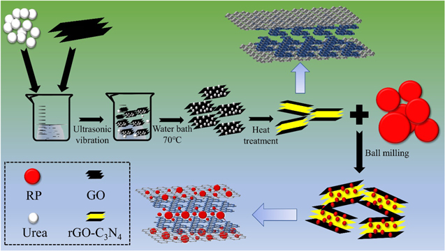
Figure 1. Schematic illustration of the preparation process of P/rGO-C3N4.
Download figure:
Standard image High-resolution imageFigure 2a shows the X-ray diffraction (XRD) patterns of the ball-milled samples. P is prepared through ball milling method for 10 h in Ar gas. The two broad humps at 15°–20° and 30°–45° in the profile of P sample reveal that the red phosphorus after ball milling is dominantly amorphous. The characteristic diffraction peaks of rGO-C3N4 are not obvious, on account of their small proportion in the composites as well as their amorphous state. In addition, the XRD patterns of rGO-C3N4 are displayed Fig. S1a (Supporting Information is available online at stacks.iop.org/JES/167/060518/mmedia).
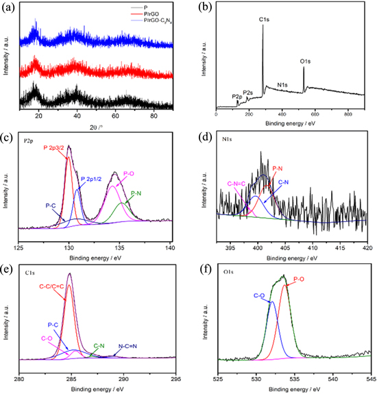
Figure 2. (a) XRD patterns of P, P/rGO and P/rGO-C3N4; XPS spectrum of the P/rGO-C3N4 composite: (b) The full spectrum of P/rGO-C3N4; (c), (d) and (f) The high resolution P2p, N1s, C1s and O1s, respectively.
Download figure:
Standard image High-resolution imageXPS analysis is also conducted to verify the elemental composition and chemical bonding situation in as-prepared P/rGO-C3N4 composite samples. As shown in the survey spectrum of P/rGO-C3N4 sample (Fig. 2b), the sample consists of P, N, C and O elements. Figure 2c illustrates the high resolution P2p spectra for P/rGO-C3N4. Five peaks centered at 129.9, 130.8, 130.4, 134.2 and 135.2 eV are corresponding to the chemical shift of P2p3/2, P2p1/2, P–C, P–O and P–N, respectively.33–36
The formation of P–C and P–N bonds in the P/rGO-C3N4 composite could significantly facilitate robust interface interconnection and thus build a fluent ion/electron diffusion tunnel between red phosphorus and the matrix framework. The electronic conductivity of the whole electrode could thus be improved. The N1s spectra of P/rGO-C3N4 hybrids could deconvoluted into three peaks as displayed in Fig. 2d.
The peak centered at 399.6 and 401.6 eV is attributed to C–N and P–N chemical bonding, respectively. In addition, a peak at 398.8 eV is related to C–N=C, which could also be observed in the previous reported C3N4.37–39 The high-resolution C1s spectra for P/rGO-C3N4 is shown in Fig. 2e. These five peaks are centered at 284.8, 285.1, 285.4, 287.1 and 288.9 eV, which is classified to the C–C/C=C, P–C, C–O, C–N and N–C=N bonding.40–43 It is rational to deducte that the excellent combination of rGO and C3N4 improves the electrical conductivity of the host material. In the O1s spectra (Fig. 2f), two peaks located at 532.0 and 533.7 eV are ascribed to C–O and P–O, respectively.
SEM images of the P/rGO-C3N4 composites with different magnifications are shown in Figs. 3a and 3b. The as-prepared P/rGO-C3N4 hybrids is composed of nubby structure with a size in the range of 40–200 nm. The SEM image of P/rGO-C3N4 evidently shows the composition of red phosphorus and rGO-C3N4 in an irregular shape. The SEM images of rGO-C3N4 are displayed in Figs. S1b and S1c. The structure of P/rGO-C3N4 composites is schemed in Fig. 3c. The configuration of red phosphorus embedded in rGO-C3N4 framework via P–C and P–N chemical bonding provides a robust structure to alleviate contrasting volumetric changes and possible interface disconnection. The energy-dispersive X-ray spectroscopy (EDS) spectrum of P, N, C and O elements (Fig. 3e) confirms the uniform distribution of P, N and C in P/rGO-C3N4 composites. HRTEM images of P/rGO-C3N4 hybrid, as displayed in Fig. 3f, reveal that the P/rGO-C3N4 consists of red phosphorus paticles and layered rGO-C3N4, which can effectively accommodate the volume change and suppress the pulverization of red phosphorus.
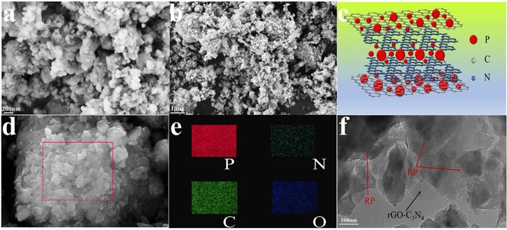
Figure 3. SEM images of P/rGO-C3N4 composite and corresponding simulative structure for the (a)–(c); (d) SEM image of P/rGO-C3N4 composite and corresponding EDS mapping of P, N, C and O (e); (f) HRTEM images of P/rGO-C3N4 composite.
Download figure:
Standard image High-resolution imageThe cycling performance of P, P/rGO and P/rGO-C3N4 electrodes at the current density of 200 mA g−1 in the voltage window of 0.02–2.5 V is shown in Fig. 4a. All specific capacities are calculated based on the total mass loading of active materials. P, P/rGO and P/rGO-C3N4 electrodes have high initial discharge capacities of 1656 mAh g−1, 2126 mAh g−1 and 2423.4 mAh g−1, respectively. P electrode only maintains a specific capacity of 104.6 mAh g−1 after 100 cycles, showing a drastic capacity fading. In comparison with P electrode, P/rGO electrode displays better cycling performance with a discharge capacity of 361.9 mAh g−1 after 100 cycles (22.2% retention). The comparison of capacity retention of P, P/rGO and P/rGO-C3N4 electrodes is shown in Fig. 4b. The capacity retention is calculated on the basis of the 2nd-cycle discharge capacity. Compared with P and P/rGO electrodes, P/rGO-C3N4 delivers the highest capacity retention of 83.2%, 74.3%, 70.0%, 64.9% and 59.4% after 20, 40, 60, 80 and 100 cycles respectively. The P electrode delivers a poor Coulombic efficiency of 8.9% after 100 cycles. It is further confirmed that the incorporation of rGO-C3N4 could significantly improve the electrochemical performance of red phosphorus.
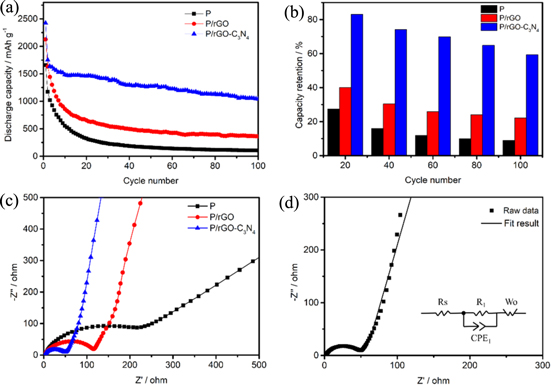
Figure 4. (a) Cycling performance of P, P/rGO and P/rGO-C3N4 electrodes at the current density of 200 mA g−1; (b) The comparison of capacity retention of P, P/rGO and P/rGO-C3N4 electrodes; (c) Nyquist plots of the P, P/rGO and P/rGO-C3N4 electrodes measured before cycling; (d) Nyquist plot of the fresh P/rGO-C3N4 electrode with the selected equivalent circuit.
Download figure:
Standard image High-resolution imageThe Nyquist plots of P, P/rGO and P/rGO-C3N4 electrodes for LIBs were presented in Fig. 4c. The electrochemical impedance spectroscopy (EIS) is recorded in the frequency range from 0.01 to 100,000 Hz. It is obvious that all the EIS plots consist of one semicircle in high frequency range and one inclined line in low frequency range, corresponding to the charge transfer impedance and the diffusion impedance of lithium ions espectively. The conductivity and the charge transfer resistanceo P/rGO-C3N4 are both relatively low. The electronic conductivity of P/rGO-C3N4 is about 9.3 times larger than the counterpart of P/rGO and about 37.3 times than that of P as shown in Table SI. Figure 4d is the Nyquist plot of fresh P/rGO-C3N4 electrode with equivalent circuit (inset). It is obvious that the plot is composed of a semicircle in the high frequency region and an inclined line in the low frequency region. As shown in Fig. 4d, the equivalent circuit includes electrolyte resistance (Rs), a constant phase element (CPE) in parallel with charge transfer resistance (R1) associated with charge transfer resistance (corresponded to the high frequency in Nyquist plot) and a Warburg resistance (Wo) corresponds to lithium ion diffusion resistance (corresponded to the low frequency in Nyquist plot). Besides, Nyquist plots of fresh P and P/rGO electrodes with equivalent circuits are displayed in Figs. S2a and S2b (Supporting Information).
The electrochemical properties of as-prepared composites are evaluated in half cells within the voltage range of 0.01 to 2.5 V. The CV curves of the P/rGO-C3N4 electrode at various scan rates of 0.1, 0.2, 0.3, 0.5, 1.0 and 2.0 mV s−1 are displayed in Fig. 5a. Excellent rate performance and relatively weak polarization of P/rGO-C3N4 composite are shown.44 Additionally, there is a linear relationship between the peak current and the square root of scanning rate (Fig. 5b). The lithium ions diffusion coefficient of P/rGO-C3N4 electrode is calculated as 1.2 × 10⁻¹² cm2 s−1, 85.7 times larger than that of P/rGO electrode (Table SI). Cyclic voltammetry (CV) test is conducted to reveal the redox behavior of P/rGO-C3N4 electrode during the process of lithiation and delithiation, as shown in Fig. S1d. In Fig. S1d, during the first reduction process, a broad and irreversible cathodic peak at ∼1 V might be ascribed to the formation of SEI layer.7 Two peaks at ∼0.65 V and ∼0.2 V are observed in the first-cycle cathodic curve, which corresponds to the lithium ion insertion reaction to form Lix P (x = 1–3) compounds. The peaks at ∼0.8, ∼0.7 and ∼0.2 V are ascribed to the lithium ion insertion reaction after the first cycle. During the oxidation process, two apparent peaks at 0.9 and 1.3 V in the first cycle and three peaks in the 2nd, 3rd and 4th cycles are attributed to the delithiation process of Lix P (x = 1–3) to P. From the 5th to the 10th anodic scans, the peaks at ∼0.85, ∼1.2 and ∼1.3 V also correspond to the delithiation process. There are no apparent potential or current changes in the redox peaks, and the position of the redox peaks overlaps completely in the CV plots from the 5th to the 10th cycle, indicating high structural stability of P/rGO-C3N4 composite. The galvanostatic charge-discharge curves of the P/rGO-C3N4 electrode for the 2nd cycle are displayed in Fig. 5c.

Figure 5. (a) Cyclic voltammetry curves of P/rGO-C3N4 composite at different scan rates: 0.1, 0.2, 0.3, 0.5, 1.0 and 2.0 mV s−1; (b) The relationship of the peak current (I) and the square root of the scan rate (v0.5) of the P/rGO-C3N4 composite; (c) Galvanostatic charge–discharge curves of the P/rGO-C3N4 composite for the 2nd cycle at the current density of 200 mA g−1; (d) Nyquist plots taken from the P/rGO-C3N4 cells after the1st, 5th, 15th, 20th, 30th and 50th.
Download figure:
Standard image High-resolution imageElectrochemical impedance spectra of P/rGO-C3N4 half-cell after the 1st, 5th, 15th, 20th, 30th and 50th cycle is presented in Fig. 5d. The resistance of fresh P/rGO-C3N4 electrode is 168 ohms, much higher than that of the cell after cycling. The resistance gradually decreases to 90 ohms after 15th cycle and finally stablizes at 70 ohms in the subseqent cycles. It is rational to deduce that electrode activation occures in the initial few cycles according to the gradual reduction of the overall resistance. The resistance tends to be stable after activation.
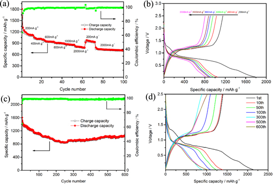
Rate performance of P/rGO-C3N4 electrode was further investigated by increasing the current density from 200 mA g−1 to 2000 mA g−1 (Fig. 6a). At the current density of 200 mA g−1, P/rGO-C3N4 sample delivers a charge/discharge capacity of 1152.5 mAh g−1/1806.1 mAh g−1 in the first cycle, while a reversible specific capacity of 998.9, 936.3, 896.6, and 855.7 mAh g−1 could be gained at the current density of 400, 600, 800 and 1000 mA g−1, respectively. Furthermore, a specific discharge capacity of 800 mAh g−1 could be kept even at the high current density of 2000 mA g−1, demonstrating an outstanding rate performance of P/rGO-C3N4 composite. Note that 84.3% capacity retention could be obtained when the current density increases from 600 mA g−1 to 2000 mA g−1. When the current density is restored to 2000 mA g−1, the P/rGO-C3N4 electrode could still maintain a superior diacharge specific capacity of 786.6 mAh g−1 and a charge capacity of 748.7 mAh g−1. Coulombic efficiency of 99.3% is retained by 100 cycles. The charge-discharge curves of P/rGO-C3N4 are shown in Fig. 6b. The similar voltage plateau at differnt current density verifies again the good rate capability.
Figure 6. (a) Rate performance of P/rGO-C3N4 at various current rates; (b) The typical galvanostatic charge-discharge curves for the 1st, 13th, 23th, 33th, 43th and 53th cycles of P/rGO-C3N4; (c) Cycling performance and the corresponding Coulombic efficiency of P/rGO-C3N4 with the potential window of between 0.02 V and 2.5 V (vs Li+/Li) at the current density of 200 mA g−1 for 600 cycles; (d) The charging–discharging profiles for the 1st,10th, 50th, 100th, 100th, 300th, 500th and 600th cycles of P/rGO-C3N4 composite at the current density of 200 mA g−1.
Download figure:
Standard image High-resolution image
Figure 6c displays the cycling performance of P/rGO-C3N4 composite within the potential window of 0.02–2.5 V (vs Li/Li+) at the current density of 200 mA g−1. P/rGO-C3N4 electrode delivers a specific capacity of 903.4 mAh g−1 with a high Coulombic efficiency of 98.3% after 300 cycles. A relatively steady cyclability could be gained on cycling. An average coulombic efficiency of 98.7% could be obtained from 300th to 600th cycle. After 600 cycles, the electrode maintains a reversible capacity of 1032.6 mAh g−1 with a high coulombic efficiency of 99.0%, exhibiting amazing cyclability and high reversibility. The electrochemical performance of rGO-C3N4 was investigated to further reveal its function on P/rGO-C3N4 composite. As shown in Fig. S2c, the initial discharge specific capacity of rGO-C3N4 electrode is as high as 1004.8 mAh g−1. However, its discharge capacity drops drastically to 432.8 mAh g−1 in the second cycle, and the capacity retention is only 292.0 mAh g−1 after 50 cycles. It reveals that the intrinsic capacity contribution of individual rGO-C3N4 in P/rGO-C3N4 composite could be almost ignored on considering about 10 wt% of rGO-C3N4 involved in the composite. As displayed in Fig. S2d, the rGO-C3N4 electrode is involved in some electrochemical reactions during the first cathodic cycle and it takes effect insignificantly.
Figure 6d represents the galvanostatic charge-diacharge profiles of P/rGO-C3N4 with the voltage range of 0.02–2.5 V at the current density of 200 mA g−1. It's noticeable that the charging curves of the 1st and 10th cycle almost overlaps, indicating the good stability of the P/rGO-C3N4 composite. The profiles of P/rGO-C3N4 for the 500th and 600th cycles apparently keep good repeatability, suggesting that the P/rGO-C3N4 electrode delivers excellent cycle life.
Conclusions
A novel P/rGO-C3N4 composite is designed and synthetized successfully via a facile high-energy ball-milling method. The strategic incorporation of rGO-C3N4 plays an important role in the formation of admiralbe interface connection between red phosphorus and rGO-C3N4 framwork via P–N and P–C bonding, leading to fluent ion/electron-diffusion tunnel and admirable mechanical strucuture. The P/rGO-C3N4 composite delivers superior rate performance and excellent cycle stability with a reversible capacity of 1032.6 mAh g−1 over 600 cycles at a current density of 200 mA g−1. This study provides a feasible strategy for designing phosphorus anode materials for battery applications.
Acknowledgments
This research is financially supported by the Natural Science Foundation of China (grant no. 21476035 and 21975036), the Fundamental Research Funds for the Central Universities (grant no. 3132019328).