

Abstract
Li/Mn-rich positive electrode materials are widely known for their high energy content, which exceeds that of current cathodes significantly. Their implementation in practical high-energy lithium ion batteries has to date been hindered by various technical challenges, most of all, their insufficient long-term charge/discharge cycling performance. Here, a new concept for designing core–shell (CS) materials for this class is introduced, which is based on cathode particles, which are specifically designed to have an anionic redox-rich core and a shell with reduced anionic redox. This material design approach aims to overcome the drawback of having the sensitive anionic redox at the electrolyte/active material interface, and, therefore, extenuating the phase degradation from layered- to spinel- or even rock salt-structure. In this work, the effect of a CS particle design with a Co-free, Mn-rich core and a Co-containing shell with lower Mn content is studied. The spherical cathode particles, produced by a Couette Taylor Flow Reactor, enable a superior electrochemical performance with excellent initial Coulombic efficiencies of 90%–95% and improved long-term cycling performances compared to the reference materials, consisting of the pure core or pure shell composition.
Export citation and abstract BibTeX RIS
Currently, the rising demand for plug-in hybrid (PHEV) and full electric (EV) vehicles leads to an increasing demand for high-energy density batteries. In order to supply this growing request, low-cost, safe, environmentally benign and ethically sourced battery components are needed.1–3 Here, the positive electrode (cathode) material is a significant cost driver in current lithium ion batteries (LIBs), especially due to high raw material costs of cobalt and nickel.4–7 Hence, the further development towards more sustainable high-energy and low-cost cathode materials needs to be pursued intensively.
Keeping these considerations in mind, the class of Li/Mn-rich layered transition-metal oxides (LMR-NCM) constitutes one of the most promising material classes for cathode materials due to their high practical specific discharge capacity ≥250 mAh g−1 and specific energy up to 1,000 Wh kg−1 at material level.8–12 These compounds contain a high amount of low-cost, non-toxic manganese due to the formal introduction of the Li2MnO3 phase13–16 compared to classical, stoichiometric layered oxide cathodes. However, numerous challenges still remain, which have mostly prevented their commercial implementation so far. These integrated-type materials often show a high irreversible capacity in the first cycle, with an initial Coulombic efficiency (ICE) of ≈70%–85%.17 Upon prolonged cycling, the electrochemical behavior typically shows a gradual voltage (and capacity) fade, which is significantly more pronounced than for conventional LiMO2-type layered cathodes (with M = Ni, Co, Mn).18 The main reason for the voltage fade lies in the liability of the anionic redox activity and its consequential processes. This source of additional electrons is characteristic for the material class and additionally causes a pronounced voltage hysteresis, compared to the one, typically found in classical layered oxides. Therefore, the voltage hysteresis between the charge and discharge processes in turn also negatively affects the material's energy inefficiency.19 Still, the utilization of this anionic redox is justified by the additional discharge capacity gained at high positive electrode potentials, i.e., ≥4.3 V vs Li∣Li+. Advanced particle design, e.g., the creation of a spherical secondary particle morphology, might help to overcome some of the material class' challenges, as it facilitates good dispersity, high tap density, fluidity and minimum exposure towards the battery electrolyte, due to a reduced specific surface area.20,21 Other performance parameters such as charge/discharge rate capability, lifetime, Coulombic efficiency, energy efficiency and safety are also influenced by the material's morphology and particle size.19,22 For the synthesis of cathode particles in this study, a Couette Taylor Flow Reactor (CTFR) was used, which uses a Taylor flow to create quasi-static reaction zones. CTFRs can be used for various preparative purposes, e.g., crystallization, polymerization and precipitation.23–27 The precipitation of transition metal (TM) oxides using the CTFR results in dense and uniformly shaped agglomerates with a narrow size distribution.25 While the precipitation of the precursor material in form of hydroxides is thoroughly studied, the precipitation in form of carbonates is only rarely investigated so far.28 Since the resulting particle morphology differs significantly between hydroxide and carbonate precursors and has a major impact on the electrochemical behavior of the cathode active material, it is worthwhile to explore the effect of carbonate-based precursor particles.
Many approaches, to improve the long-term charge/discharge cycling performance of LMR-NCM materials have been reported in the literature so far. Often, a surface modification is applied in order to overcome the intrinsic drawbacks, such as structural transformation or even deterioration through subsequent oxygen loss upon cycling. Therefore, common improvement strategies include coating of the cathode particles,29–31 doping/substitution of cations32–34/anions35,36 or functionalization via in situ cathode electrolyte interphase (CEI) formation through electrolyte additives.37,38 However, most of these approaches address the active material/electrolyte interface rather than the bulk structure and, therefore, may not consider to solve the underlying structural problem. The anionic redox contribution increases the risk of oxygen evolution at the electrode/electrolyte interface, which should be kept minimum in this very spot.39 Therefore, the use of a core–shell (CS) concept to design cathode particles offers an integrated approach making use of the class' own characteristic, i.e., the active cationic and anionic redox process. Hence, a particle design based on a core with higher anionic redox contribution and a shell with lower anionic redox contribution was built. The particles were designed to exhibit a compositional variation of the transition metals between core and shell, while the lithium content is kept constant.
Tackling the poor capacity retention, the anionic redox process needs to be focused on.40 Increasing the manganese content is known to be most effective to stabilize the anionic redox quantitatively, due to the fact that the Mn–O bond is the overall strongest 3d-metal-O bond.41 Especially, the manganese content of the transition metal site of the R-3m-phase (LiMO2) should be targeted in order to preserve the desired ratio of the monoclinic Li2MnO3 and the rhombohedral LiMO2 phase. Therefore, the Mn content of the cathode is considered to be crucial for defining the fine line between oxygen loss and reversible oxygen redox.42,43
Simultaneously, decreasing the Co content results in advantages with regard to cost as well as the environmental/ethical footprint. Nevertheless, Co is known to enable a higher average discharge potential in LiMO2∣∣Li metal cells.44 Hence, a concept, which combines the above-mentioned features is needed. The idea of a CS particle design is intriguing and has already been successfully realized for stoichiometric, Ni-rich NCM layered oxides.45 A Co-free, Mn-rich particle core combined with a Co-containing outer shell may lead to a more stable electrochemical performance. Hereby, keeping the stoichiometric difference small is the key for achieving low gradients in the material and therefore enabling a successful synthesis of a real LMR-NCM CS cathode material.46
Accordingly, the present study focuses on the synthesis of an LMR-NCM CS particle design with a Co-free, Mn-rich core and a shell lower in Mn with small quantities of Co, showing an improved electrochemical performance compared to the prepared reference compounds with the transition metal composition of the shell and the core (in the following abbreviated as "S-only" and "C-only") as well as very high ICEs.
Experimental
NiSO4 6 H2O (98%, Alfa Aesar), CoSO47 H2O (≥99%, Acros Organics), MnSO4H2O (≥99%, Acros Organics), Na2CO3 (99.5%, Acros Organics), Li2CO3 (99%, Acros Organics) and NH3H2O (25%, Acros Organics) were used as starting materials for synthesis. The active material samples Li1.14Ni0.23Co0.11Mn0.52O2 (further abbreviated as "S"), Li1.14Ni0.23Mn0.63O2 (further abbreviated as "C") and Li1.14Ni0.23Co0.06Mn0.57O2 (50 vol% S, 50 vol% C; further abbreviated as "CS") were manufactured by the following procedure: First, the precursor materials Ni0.27Co0.13-xMn0.60+xCO3 (x = 0, 0.065, 0.13) were obtained by continuous co-precipitation using a Couette Taylor Flow Reactor (CTFR, Terra 3300, Laminar). Therefore, a 2 M solution of the transition metals (TM) and a 2 M solution of Na2CO3 including 0.2 M NH3H2O (mixture in the following called "base") as chelating agent were prepared. The CTFR was initially filled with distilled water, followed by the addition of the reactant solutions via membrane pumps (SIMDOS02, KNF). The base was added under pH-controlled conditions with aid of a pH-meter (Dulcotest® ProMinent). To achieve the CS sample, the required amount of the stoichiometric 2 M TM solution and 2 M base for the shell was added after half the dwell time at half the length of the reactor tube. The flow rates were adjusted based on the target shell-thickness of 50 vol%. The calibration of the pH-electrode was done at room temperature using buffer solutions with pH-values of 7.0 and 10.0 (Dulcotest® ProMinent). The CTFR always operated at a constant temperature of 60 °C, an inner cylinder rotation speed of 1300 rpm and at a pH-value of 8.5 with a mean residence time of 4 h. These instrument parameters were optimized in preliminary studies. After passing 20 h, a sample suspension was taken at the steady state, decanted and washed 8–10 times with distilled water and finally dried in an oven (80 °C for 24 h) and under reduced pressure (120 °C for 48 h, ≤10−3 mbar).
The dried precursor was stoichiometrically mixed with 1.5% excess of Li2CO3 (linear combination of the amount for C-only 50% and S-only 50%) using mortar and pestle, which was then decomposed in a muffle furnace (5 K min−1, 5 h at 485 °C). Secondly, the resulting powder was reground and heated again in a muffle furnace (5 K min−1, 6 h at 850 °C) to obtain the active material (AM).
The structural investigation was done by X-ray diffraction (XRD, Bruker D8 Advance) using Cu Kα radiation in a Bragg-Brentano geometry. Rietveld refinements of the collected data were achieved by using the Topas software (v4.2; Bruker AXS GmbH). The chemical composition was determined by an inductively coupled plasma-optical emission spectrometer (ICP-OES, Spectro ARCOS EOP). Scanning electron microscopy (SEM) and energy dispersive X-ray spectroscopy (EDX) analyses were carried out using a Zeiss Auriga electron microscope (Carl Zeiss Microscopy GmbH). For the SEM images, a typical working distance of 3.5 to 4 mm and an accelerating voltage of 3 kV was used. The FIB-SEM milling was done by a Ga-beam with a specific current of 2 nA. EDX was carried out at a magnification of 1 kx or 2.5 kx, at a working distance of 5 mm and an accelerating voltage of 20 kV with an energy-dispersive X-ray detector (X-MaxN 80 mm2, Oxford Instruments). The particle size distribution was determined with a laser diffraction analyzer (CILAS 1064) in an aqueous dispersion under addition of a surfactant.
The electrode paste consisted of the AM, conductive agent (CA, Super C65, Imerys Graphite & Carbon) and binder (polyvinylidene difluoride (PVdF), Solef 5130, Solvay) in a ratio of 85:10:5 by weight and N-methyl-2-pyrrolidone (NMP, Sigma-Aldrich, 99.5%) as solvent with a solid-to-liquid ratio of 36%. The paste was dispersed with a mixer mill (MM 400, Retsch GmbH) using zirconium oxide milling jars (10 ml) and milling balls (10, Ø 5 mm) for 90 min at 20 Hz. Subsequently, the paste was cast onto aluminum foil (Goodfellow, washed with acetone) with a doctor blade (gap height 100 μm, ZAF 2010, Zehntner) and a film applicator (SH1133N, Sheen Instruments) with a casting speed of 50 mm s−1. After drying in the oven (80 °C, 2 h), the electrode sheets were punched into circular electrodes (Ø 12 mm), dried overnight (120 °C, reduced pressure ≤10−3 mbar) and pressed (≈4.4 t cm-2 for 15 s). The active mass loading of the studied electrodes ranged from 2.7 to 3.2 mg cm−2. All electrochemical cells were assembled in a glove box (UNIlab, MBraun) under argon atmosphere (H2O and O2 both ≤0.01 ppm).
The galvanostatic charge/discharge experiments were done at a Maccor Series 4000 automated test system at 20 °C. The test procedures started always with a 12 h rest step under open circuit voltage conditions, followed by a formation cycle at 0.1 C (1 C = 250 mA g−1; corresponding to a typical practical discharge capacity of 250 mAh g−1) with cut-off potentials at 2.0 and 4.6 V vs Li∣Li+ (4.7 V for the 1st cycle) for the working electrode (WE).
All electrochemical experiments were carried out in three-electrode T-cells (Swagelok, custom in-house design; half-cell setup) with Li metal foil (battery grade, Albemarle, Ø 12 mm) as counter (CE) as well as reference (RE) electrode. The polymer separator (6 layers Freudenberg 2190, Ø 13 mm) was soaked with 140 μl electrolyte (1 M LiPF6 in EC:EMC (3:7 by weight), battery grade, components by BASF SE) and additional 60 μl for the separator of the reference electrode (3 layers Freudenberg 2190, Ø 8 mm). To ensure a high reproducibility, for each electrochemical experiment, at least three different cells were analyzed, while the corresponding standard deviations are shown in the graphs.
Results
Chemical analysis
The chemical composition, as shown in Table I, was determined via ICP-OES. The results show a good agreement between the targeted and resultant stoichiometry. As expected, CS compound shows the average Co and Mn content of C and S. The resulting Li content is slightly lower than intended, leading, however, to positive effects concerning the ICE during the charge/discharge experiments (see Discussion).
Table I. Average chemical composition of prepared materials determined by ICP-OES.
| Targeted stoichiometry | Li | Ni | Co | Mn | |
|---|---|---|---|---|---|
| Core | Li1.14Ni0.23Co0.00Mn0.63O2 | 1.09 | 0.24 | 0 | 0.67 |
| Shell | Li1.14Ni0.23Co0.11Mn0.52O2 | 1.13 | 0.20 | 0.12 | 0.55 |
| core–shell | Li1.14Ni0.23Co0.06Mn0.57O2 | 1.08 | 0.24 | 0.06 | 0.62 |
Bulk structure analysis via X-ray diffraction
Figure 1 shows the XRD patterns of the samples Li1.14Ni0.23Co0.11Mn0.52O2 (S), Li1.14Ni0.23Mn0.63O2 (C) and Li1.14Ni0.23Co0.06Mn0.57O2 (CS). All major reflections were indexed by the rhombohedral LiMO2 structure (R-3m) (ICDD PDF# 04-014-8375). The reflections between 2θ = 20.0 and 22.5° represent characteristic superlattice reflections caused by Li/Mn ordering within the transition metal slab of the monoclinic Li2MnO3 structure (C2/m).

Figure 1. XRD diffraction patterns of C-only (Core), S-only (Shell) and CS (core–shell) material. The asterisks mark the super-lattice reflection caused by Li/Mn-ordering in the additional C2/m phase. The patterns are normalized to the (003) reflection (2θ ≈ 18.6 °), while the Miller indices correspond to the R-3m phase. At the bottom of the graph, reflections of a LiNi0.33Co0.33Mn0.33O2 structure (ICDD PDF# 04-014-8375) are shown for reference.
Download figure:
Standard image High-resolution imageTable II shows the results of the Rietveld refinement based on the obtained XRD data. Refinement was performed applying only the rhombohedral structure (R-3m). The core–shell material, which consists of two, spatially separated two-phase composite structures, is structurally complex and difficult to study with a long-range averaging method such as XRD. Hence, the here applied model is a simple way to compare these systems and still exhibit a satisfactory goodness of fit (χ2). The refined a- and c-lattice parameters of the compounds are in a similar range. Nevertheless, the cell volume is the smallest for the S-only material (100.43(1) Å3) compared to the other two (C: 100.78(2) Å3, S: 100.76(1) Å3). However, no clear trend is visible. The absolute intensity ratio of I003/I104 was calculated and found to be above 1 for all samples and, therefore, indicating the formation of a layered structure.44,47 Similarly, a lower value for the absolute intensity ratio of I102+006/I101 within the layered structure suggests a good separation of Li+ and TM ions into their respective layers.44 In this case, the I102+006/I101-ratio is nearly in the same range (C:0.36, S:0.30 and CS:0.34). Accordingly, a good cation ordering can be assumed.
Table II. Structural parameters for C-only, S-only and CS material resulted from Rietveld refinement using R-3m space group.
| a [Å] | c [Å] | V [Å3] | I003/I104 | I102+006/I101 | Rwp | χ2 | |
|---|---|---|---|---|---|---|---|
| Core | 2.8560(2) | 14.266(2) | 100.78(2) | 1.22 | 0.36 | 3.41 | 3.99 |
| Shell | 2.8525(9) | 14.253(1) | 100.43(1) | 1.85 | 0.30 | 2.22 | 3.00 |
| core–shell | 2.8574(1) | 14.251(2) | 100.76(1) | 1.51 | 0.34 | 2.60 | 3.24 |
Particle morphology
The particle and surface morphology and chemical composition were studied by SEM and EDX, respectively, and the particle size was determined through laser diffraction. Both approaches were used to gain insights into the primary and secondary particle size, shape and chemical composition.
Particle size analysis
The particle size distribution of C-only, S-only and CS was studied and the results are presented in Fig. 2. The three samples share a bimodal particle size distribution. The first peak at ≈ 0.3 ± 0.2 μm represents the fraction of smaller particles, with a volume fraction of 23% for CS, <13% for C and <1% for the S. The narrow main peak at 1–24 μm represents the largest particles for CS (≈11 μm) and C-only (≈11 μm), followed by S-only (≈7.5 μm). The D10, D50 and D90 values confirm this trend. For the shell material, all values are closer together (2.7, 6.5, 10.7 μm), indicating a very narrow distribution. For C (0.3, 7.8, 14.1 μm) and CS (0.2, 6.5, 13.7 μm) the values are in a similar range and shifted to slightly higher values in the main area. All prepared secondary particles fall into the targeted size range of 2–20 μm.
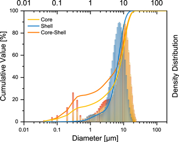
Figure 2. Particle size distribution (by volume), obtained by particle size analysis of the studied active material powders.
Download figure:
Standard image High-resolution imageScanning electron microscopy and energy dispersive X-ray spectroscopy
Figure 3 shows the SEM images for all samples taken at different magnifications. The size distribution of the C-only and CS sample is similar and the average particle size is slightly larger than the S-only equivalent (Figs. 3a–3c). These results are in good agreement with the results determined by laser-diffraction before. For all three samples, the secondary particles appear in a spherical shape with smooth surface (Figs. 3d–3f). The primary particles, however, are in the range of 50 and 200 nm (C), 100–200 nm (S) and 150–250 nm (CS) and exhibit the typical appearance for a carbonate-based co-precipitation route (grained surface compared to the flower-like appearance of hydroxides), as seen in Figs. S1a–S1c (available online at stacks.iop.org/JES/167/060519/mmedia).
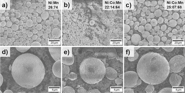
Figure 3. SEM images of the (a), (d) C-only product, (b), (e) S-only product and (c), (f) CS product; transition metal composition obtained by EDX.
Download figure:
Standard image High-resolution imageThe transition metal stoichiometry was determined by EDX and reveals the values corresponding to the outer sphere composition. In Fig. 3a, the targeted elemental composition for the core (Ni:Mn 26:74) and in Fig. 3 b the composition for the shell (Ni:Co:Mn 22:14:64) are presented. Figure 3c shows the stoichiometry of the CS material (Ni:Co:Mn 25:07:68) as a good average of the C-only and S-only composition, therefore, indicating the successful co-precipitation of a core–shell compound. The obtained chemical compositions are in agreement with the ICP-OES data already presented. Still, this method is not valid to differentiate between the individual core- and shell-composition within the CS material. Thus, a cross sectional study is necessary.
Focused ion beam-scanning electron microscopy cross sectional study
The transition metal distribution of the samples cross sections was investigated via focused ion beam (FIB)-SEM (s. Fig. 5). For that, particles were placed on carbon tape or silver-coated carbon tape. Then, particles in the size range of 10–19 μm were selected and the center of the particle was cut into a ≈1 μm thin slice, as it is schematically demonstrated in Fig. 4. This was done by milling towards the particle center, then successively thinning from the back of the particle, until the targeted thickness was achieved. This procedure was necessary, to minimize the falsification of the EDX measurement through material below the area of interest, which might vary in its elemental composition (see comparative study shown in Fig. S3 of the Supporting information).

Figure 4. Schematic illustration of the particle preparation (orange: core; grey: shell) for the EDX line scan via FIB-milling.
Download figure:
Standard image High-resolution imageIn the next step, an EDX measurement along a line from the far left to the far right through the center was performed, using ≈20 measurement points for each particle. Each measurement was performed at least three times on the same particle and repeated on different ones to verify its reproducibility.
The cross sectional SEM images of the prepared particles reveal an onion-like morphology with a small core of primary particles agglomerated in the center (compare Figs. 5b, 5f, 5h), around which multiple layers with a total thickness of about 100–500 nm are wrapped. This morphology was predefined by the precipitated precursor, where this structure can already be seen (Fig. 5f). The S-only sample shows a more porous structure and no distinct layering within the core (Fig. 5d). In this regard it differs from the C-only (Fig. 5b) and CS sample (Fig. 5h) with a regularly shaped structure, just as described (compare Fig. S2). The CS product exhibits no difference in the morphology between the core and the shell and no distinct boundary can be seen in the SEM images (Figs. 5h and S2d), which is often present for hydroxide-based compounds.48

Figure 5. Cross sectional SEM images and corresponding EDX measurements of the transition metal distribution. (a) exemplary top view onto a cut particle slice; line scans (stoichiometrically) for (b) the C-only product, (d) the S-only product, (f) the CS precursor and (h) the CS product; line scans (individual normalized stoichiometry) for (c) the C-only product, (e) the S-only product, (g) the CS precursor and (i) the CS product; dashed lines in parts (b), (d), (f), (h) show the intended values based on the ICP-OES results; note various interuptions of the oordinate.
Download figure:
Standard image High-resolution imageThe C-only material should have a homogeneous TM composition of 26.7 at% Ni and 73.3 at% Mn from the particle core to its surface. The EDX-study, however, demonstrates a small gradient across the particle with a Ni-enriched shell and a Mn-enriched core (Fig. 5b), which becomes even more apparent in the normalized representation shown in Fig. 5c. Based on the investigation of the C-only precursor (Figs. S4a, S4b), which does not exhibit any TM gradient, the gradient is likely to be formed during the calcination step, in which lithium is inserted. Owing to the high calcination temperature (850 °C), the energy barrier for the TM diffusion is likely to be exceeded. Similar migration behavior without intended gradient was previously reported by Chen et al.49 In general, all the EDX measurements in this work suffer from an intensity attenuation going from the left to the right site of the particle, which is intrinsic to the instrumental setup.
Apart from minor deviations, the S-only material exhibits a relatively constant TM distribution (Figs. 5d, 5e), as it is intended. The CS precursor on the other hand shows a Co gradient, with a Co content close to ≈0 at% in the particle core and nearly ≈7 at% near its surface, with a shell thickness of ≈5 μm (corresponding to ≈26.3 vol% of the particle). This is less Co than expected for the shell (see Fig. 5f) and the shell thickness is higher than anticipated ≈2 μm (corresponding to 10.5 vol%). The inverse trend is visible for Mn, which is enriched in the particle core and depleted at its surface. The CS particles also show a narrow Ni gradient with a slightly lower Ni concentration in the particle core (Fig. 5f). After the calcination of the CS precursor, all gradients are flattened (Fig. 5h). Co ions migrate alongside their gradient towards the particle center and concurrently, Ni ions migrate towards the particle shell. Here, the compensation of the Co migration occurs predominantly through Ni instead of Mn, since the Ni/Co interdiffusion is much faster than the Ni/Mn or Co/Mn diffusion, resulting from a lower activation energy.46,50 By virtue of the normalized representation in Fig. 5i, one can still see the presence of a Co gradient, with a similar intensity as for Ni.
Electrochemical characterization
The following charge/discharge cycling procedure was used for electrochemical characterization of the prepared positive electrodes in a half-cell setup (three-electrode configuration), allowing a precise control of the WE potential51: The first-activation cycle involves a charge (=de-lithiation), up to 4.7 V vs Li∣Li+ at 0.1 C (=25 mA g−1), which is followed by a discharge (=lithiation) down to 2.0 V vs Li∣Li+. All following charge/discharge cycles were carried out in the WE potential window between 2.0 and 4.6 V vs Li∣Li+. After two consecutive cycles at the same rate, further 100 cycles at 0.5 C and again three cycles at 0.1 C were performed, to investigate whether any kinetically induced effects occurred. Figure 6a shows the discharge capacity over the course of 200 cycles. Here, the investigated materials start with an initial discharge capacity of 247 mAh g−1 (C-only), 256 mAh g−1 (S-only), 259 mAh g−1 (CS) at 0.1 C and, thus, a small capacity difference between S-only and CS and a ≈10 mAh g−1 lower capacity of the C-only material can be noticed. The Co-free C-only material performs well compared to similar compounds previously reported.52–55 This trend continues throughout extended cycling, while the capacity gap between S-only and CS steadily increases, especially when increasing the rate to 0.5 C. Therefore, Li-intercalation/deintercalation of the CS material proves to be less hindered at higher applied currents compared to the C-only and S-only material.
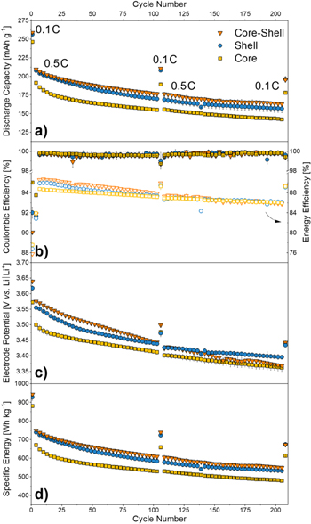
Figure 6. Galvanostatic investigations of C-only∣∣Li metal, S-only∣∣Li metal and CS∣∣Li metal cells at 125 mA g−1 and three activation cycles at 25 mAg−1 and after every 100 cycles (half-cell setup, three-electrode configuration). Potential range: 4.7–2.0 V vs Li∣Li+ (1st cycle) and 4.6–2.0 V vs Li∣Li+ (following cycles). The course of (a) the specific discharge capacity (b) the Coulombic efficiency and energy efficiency (empty symbols) (c) the average discharge potential (d) the specific energy at material level is shown.
Download figure:
Standard image High-resolution imageTable III provides the corresponding cathode discharge capacities and ICEs of the cells. All materials attain an excellent ICE of over 90%, while the C-only material reaches the highest value with remarkable 94.5% compared to literature known values with an ICE of ≈78%–90%.52,54 Thereby, these values of unmodified materials clearly outperform even similar surface optimized cathode materials.17 This is possible due to the particle morphology, predefined by the co-precipitation in the CTFR, and a calcination with low Li-excess (i.e., 1.5 at% excess vs 5.0 at% excess; see Fig. S5a), resulting in a structure with lower Li content than theoretically necessary. The last synthesis step probably results in a more favorable structure containing a higher amount of vacancies. Furthermore, the superiority of the CS concept can be demonstrated by direct comparison of the trend in discharge capacity, which is superior to the inverse particle design ("shell-core" (SC) design) with a Co-containing core and a shell with larger amounts of anionic redox (see Fig. S5a).
Table III. Initial Coulombic efficiency (ICE), initial cationic/anionic charge capacity (ICCC/IACC) and capacity retention (CR) values after 106 and 209 cycles of Li1.14Ni0.23Mn0.63O2 (Core), Li1.14Ni0.23Co0.11Mn0.52O2 (Shell) and Li1.14Ni0.23Co0.06Mn0.57O2 (CS)∣∣Li metal cells.
| ICE [%] | ICCC [mAh g−1] | IACC [mAh g−1] | CR 106th/3rd [%] | CR 209th/3rd [%] | |
|---|---|---|---|---|---|
| Core | 94.5 ± 0.00 | 85 (32%) | 178 | 84.6 | 80.3 |
| Shell | 91.5 ± 0.55 | 115 (40%) | 175 | 86.1 | 81.4 |
| core–shell | 90.1 ± 0.14 | 105 (38%) | 174 | 86.8 | 80.2 |
Analyzing the cationic (capacity  4.33 V, ICCC) and anionic (capacity
  4.33 V, IACC) contribution to the initial charge capacity, one can see the following trend: The increase of Ni and Co content in the material (i.e., from 23% to 34%) leads to an increase of the cationic contribution, nominal and by percentage from C-only (32%), CS (38%) to S-only (40%), as expected. This finding, on the other hand, means that the C-only material exhibits the highest anionic redox capacity contribution.
After the first 100 cycles, the materials show a capacity retention of 84.6% (C), 86.1% (S) and 86.8% (CS), respectively. The attainable capacity of all three materials fades slowly within the next 100 cycles to nearly 80% of their initial values, while the S-only material still shows 81.4%. The Coulombic efficiencies (Fig. 6b) are above 99.5% for the whole cycling period (from the 3rd cycle on). Figure 6c gives an overview of the average discharge potential upon cycling. Here, the S-only and CS material start with ≈3.62 and ≈3.64 V, respectively, whereas the C-only material starts at a lower potential of ≈ 3.57 V. After the first 100 cycles, all mean discharge potentials converge, whereas the S and CS material still show a slightly higher potential, which continues for the next 100 cycles until they merge at ≈3.36 V. Therefore, the S-only and CS material show a more pronounced potential fade, which is also reflected in Fig. 6b, where the energy efficiency of CS decreases the most. However, the next 100 cycles show the same trend as the other materials, which, keeping the discharge capacity and potential in mind, indicates a slightly lower charge potential, possibly indicating structural change upon cycling. In contrast, the C-only material operates at overall lower potentials, probably due its Co-free composition. As a result, the trend of the specific energy (at material level) in Fig. 6d is identical to that of the capacity. S-only (928 Wh kg−1) and CS (943 Wh kg−1) start at comparably high values vs C-only (879 Wh kg−1). After 200 cycles still 673 Wh kg−1 (S-only), 672 Wh kg−1 (CS) and 613 Wh kg−1 (C-only) remain.
Differential capacity
In Fig. 7 the first and fifth cycle of all samples is depicted as differential capacity (dQ/dV) plot as a function of the WE potential (vs Li∣Li+). The potential window of electrochemical activity lies between 2.6 and 4.6 V vs Li∣Li+. In the first cycle (Fig. 7a), two major peaks are visible during charge. The first peak appears at ≈3.82 V for C-only and ≈3.98 V for S-only, whereas the CS material shows two oxidative peaks (≈3.82/3.98 V). The second peak, resulting from the oxygen activation, lies at ≈4.57 V (C), ≈4.57 V (S) and ≈4.53 V (CS). Therefore, it can be assumed that this process is similar for all three materials. In the fifth cycle, three major charge peaks are present at ≈3.60, ≈3.80 and ≈4.40 V and three major discharge peaks at ≈3.60, ≈3.75 and ≈4.30 V. In case of the C-only material a further redox peak-couple at ≈3.25 and ≈3.10 V appears.

Figure 7. Differential capacity plots (dQ/dV) of a C∣∣Li metal, S∣∣Li metal and CS∣∣Li metal cell in the WE potential window of (a) 1st cycle: 2.40–4.70 V vs Li∣Li+ and (b) 5th cycle: 2.40–4.60 V vs Li∣Li+. The (a) 1st cycle at 25 mA g−1 and (b) 5th cycle at 125 mA g−1 of each sample is shown.
Download figure:
Standard image High-resolution imageDiscussion
In the past, many approaches have been pursued to improve the long-term cycling performance of LMR-NCM materials. In many cases surface modifications have been the choice to overcome the intrinsic drawbacks of this class, such as structural transformation or even deterioration through subsequent oxygen loss upon cycling. As the interface between electrolyte and cathode active material is critical, several methods target it, e.g., by coating of the cathode particles,29–31 doping/substitution of the host structures cations32–34 or anions35,36 as well as functionalization through electrolyte additives37,38 for efficient cathode electrolyte interphase (CEI56,57) formation.
However, these approaches usually neglect two major points, first, the important role of the reversibility of the anionic redox. This process should be stabilized, since it is very prone to the irreversible loss of oxygen at the surface and, as a consequence, leads to faster deterioration of the cycling stability. Second, keeping the cathode particle in its entirety in mind and therefore developing concepts addressing the particle bulk is very important, as this can lead to an overall increase and stabilization of the specific capacity and energy over cycling.
In contrast, the use of a core–shell concept to design cathode particles offers the possibility of an integrated approach. Lowering the anionic redox in the shell and a Co-free core with higher anionic redox contribution is a valid approach. Showing no obvious morphological differences in the cross sectional SEM images, it offers the advantage of a structurally stable, functional secondary particle for superior cycle life.
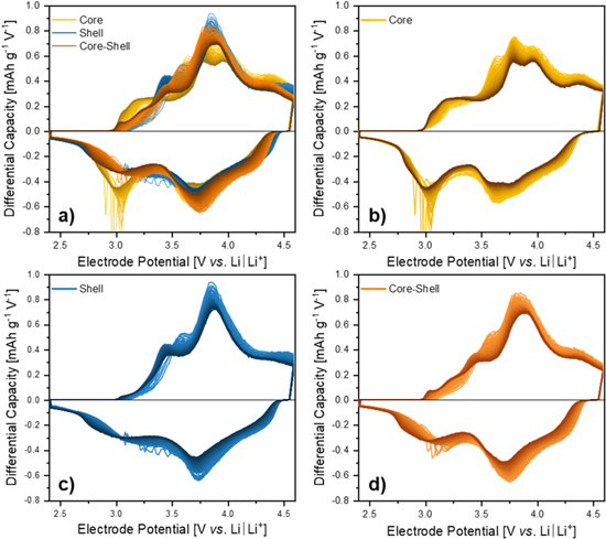
Figure 8 shows the differential capacity plot (dQ/dV) of the three samples, i.e., C-only, S-only and CS as well as the overlay of all three materials. Here, the cycles 5 to 100 are presented, transitioning from light to dark color with increasing cycle number. The most intense redox peak of all samples is ≈3.80/3.75 V vs Li∣Li+, which mainly represents the kinetically fast cationic redox activity of Ni and Co within the LiMO2-domain.58 It is commonly accepted that the oxidation traverses Ni2+/3+/4+ and Co3+/4+.58 The higher oxidation states are probably just a more formal phenomenon and not present all the time due to the constantly changing transition metal-oxygen binding states, transitioning from an ionic to a more covalent character upon charge. This behavior maintains throughout cycling in an attenuated form. The cationic redox of Mn3+/4+ lies at lower potentials (≈3.20/3.10 V vs Li∣Li+), which is more pronounced for the Mn-rich C-only sample (Fig. 8b).55,58 This redox process successively appears due to the irreversible loss of lattice oxygen upon cycling, followed by a densification of the material.39,59,60 During this process, the Li2MnO3-like (with Mn4+, O/Mn = 3) species can be reduced to a LiMnO2- (with Mn3+, O/Mn = 2) or LiMn2O4-like (with Mn3.5+, O/Mn = 2) species, which enables the Mn3+/4+ redox.40 In the beginning, this area of redox peaks provides the lowest capacity contribution, while showing a larger hysteresis compared to the Ni and Co redox.55 Since the amount of Li2MnO3 is the same in all samples (x = ⅓) and the C-only sample shows an increased Mn3+/4+ activity, an activity of this redox couple within the LiMO2-domain due to an increased amount of Mn could be assumed. On the other hand, an additional anionic redox activity could also explain this observation.
Figure 8. Evolution of the differential capacity upon prolonged constant current charge/discharge cycling (half-cell setup, three-electrode configuration) as a function of the WE electrode potential between 2.4–4.6 V vs Li∣Li+ for (a) all three samples as an overlay, (b) C-only, (c) S-only, and (d) CS material; going from the 5th cycle (bright color) to the 100th cycle (dark color) all cycled at a specific current of 125 mA g−1.
Download figure:
Standard image High-resolution image
Analyzing the progress of these cationic redox processes in Figs. 8b–8d during galvanostatic cycling, an expected slight increase in the hysteresis of Ni and Co activity (≈3.85/3.70 V, 100th cycle) appears. At the same time, the Mn3+/4+ contribution shifts to lower potentials (≈3.10/2.82 V, 100th cycle), while maintaining or even slightly increasing the capacity, which is in good agreement with literature.40,55 As a consequence, the energy efficiency of the CS material changes the most during the first 100 cycles, as discussed before. This unique fading behavior makes the Mn3+/4+ activity easy to track, since it is the only redox process with increasing intensity upon prolonged electrochemical cycling. It also makes this activity visible for the S-only and CS material, which is not very pronounced at the beginning of cycling.
During charge, partial oxidation of lattice oxygen O2−/n− (n < 2) over the whole range of the represented potential window is observed.40,58 In contrast, the corresponding On−/2− reduction takes place over the entire range of the discharge potential window. Compared to the cationic redox processes, the anionic redox generally exhibits a pronounced voltage hysteresis, which is quasi static and does not occur due to kinetic polarization phenomena.52,61–64 When it comes to the assignment of the particular peaks within the whole region, this large hysteresis of the anionic redox becomes apparent. In the lowest potential range of 3.00 to 3.50 V the processes occur for all samples over the whole range parallel to the already mentioned Mn3+/4+ redox activity. They find their equivalents in the broad peak at ≈2.70–3.50 V during discharge. In addition to the cationic activity of Ni2+/3+/4+ and Co3+/4+ between 3.50 and 4.10 V, an underlying anionic contribution occurs during these oxidative processes and finds its corresponding part also mainly in the range below 3.50 V during discharge. Here, the C-only material shows an extra peak at ≈3.95 V during charge, which is also related to the oxygen O2−/n− oxidation. This capacity gain finds its counterpart within the peak at ≈3.10 V during discharge.52,65 There is no explicit extra peak for the S- and for the CS material. Since the only difference between C-only and S-only/CS materials is the amount of Co and Mn within the LiMO2 phase, and the peak just occurs in the sample without Co, the additional Mn is likely to be the reason. Therefore, due to Mn having the strongest 3d-metal-O bonds overall, one can assume that the presence of Mn stabilizes the anionic redox the most.41 A similar behavior appears for the oxidative peaks above 4.10 V up to 4.60 V. They find their corresponding peaks in the whole range of 4.60 V down to 2.50 V, hence, showing a higher hysteresis. According to Assat et al. parts of this anionic redox process at ≈4.10–4.60 V find their counterpart in the range of ≈4.00–4.50 V.58 Thus, an anionic redox couple with a lower hysteresis exists in the high potential range. These characteristics of the anionic redox show appearance for all considered materials.
Furthermore, there is an inconspicuous shoulder in the initial cycles at ≈3.56 V during charge for S-only and CS, while for C-only, it appears at ≈3.73 V. The associated reduction takes probably place in the potential range below ≈3.50 V. Assat et al. assign this redox process also to the Mn3+/4+ activity.40 However, taking a look at the progress of this shoulder upon cycling, an interesting behavior occurs. For the C-only material, the intensity decreases at a constant potential, as depicted in Fig. 8b. This is in contrast to the typical behavior of the Mn3+/4+ activity described above. In the S-only and CS material, this shoulder loses intensity as well, whereas from cycle 10 onwards, a new shoulder in nearly the same region at ≈3.44 V arises. This new shoulder then also loses intensity while shifting to higher and not lower potentials (≈3.48 V), as depicted in Figs. 8c, 8d. Here, two questions arise: First, is this shoulder really related to the Mn3+/4+ activity or associated with an anionic redox considering the cycling behavior? Second, could the appearance of the new shoulder within in the S and CS material be caused by multiple structural changes? Unfortunately, these questions cannot be definitely answered without further investigations to track the participation of O and/or Mn, e.g., by X-ray absorption spectroscopy studies.
Following the course of anionic redox over cycling, one can find a decrease in intensity in general, while the oxidative peaks slightly shift to higher and the reductive to lower potentials, thus, increasing the voltage hysteresis. The overall development shows a decline of the high potential redox activities, while the low potential region grows. This causes the voltage fading observed in Fig. 6c, as a consequence of irreversible changes in the materials structure. Since this behavior also occurs in the CS material, the underlying processes must be a bulk-related phenomenon.
After the detailed assignment of all the redox peaks, it is worthwhile to take a closer look at the relationship between the differential capacity plot of C-only and S-only in regard to the CS. By direct comparison, shown in Fig. 8a, the CS plot reveals to be a direct average value of the S-only and C-only curve. This would mean that the CS material gains capacity over the C-only material mainly in the region of Ni and Co activity during charge. The same applies during discharge, however, here an additional capacity gain in the range between 3.75 and 4.40 V appears. This shifts the average discharge potential to slightly higher values (see Fig. 6c) with direct impact on the specific energy (Fig. 6d). The CS material exhibits a clear advantage in the high potential range (>3.75 V) compared to the C-only material. In comparison to the S-only material, it gains additional discharge capacity in the low potential range (<3.00 V). This in turn explains the superior capacity retention of the CS material over the C-only and S-only material.
On the other hand, both the CS and the S material show the same strong voltage fade upon cycling, which could be caused by two reasons. First, the addition of Co leads to an increased structural change through TM migration. Second, the lack of additional Mn leads to quantitatively more oxygen loss than oxygen redox and, therefore, causing structural changes in this way.
Conclusions
In this study, a Li/Mn-rich core-shell (CS) cathode material based on the new concept of combining a core (C), rich on anionic redox and a shell (S) with a lower anionic redox activity was designed via a CTFR synthesis. This compound with a Co-free, Mn-rich core and a shell lower in Mn and with small quantities of Co showed superior electrochemical behavior compared to the C-only and the S-only materials. A continuous CTFR was used to co-precipitate the carbonate precursors for the C-only, S-only and CS. The resulting spherically shaped particles exhibited a narrow particle size distribution and a smooth surface morphology. The elemental composition of the whole particle was determined by cross sectional FIB-SEM investigation combined with EDX spectroscopy and proved the existence of a CS material. The inside of the particle exhibits a uniform, onion-like texture with no differences in the core- and shell-morphology, showing no obvious phase boundary, which is a major criterion for a stable electrochemical long-term performance. The materials reach first cycle discharge capacities of 247 mAh g−1 (C), 256 mAh g−1 (S) and 259 mAh g−1 (CS) in Li metal half-cells, with excellent initial Coulombic efficiencies of 94.5%, 91.5% and 90.1%, respectively. The specific energy of 879 Wh kg−1 (C), 928 Wh kg−1 (S) and 943 Wh kg−1 (CS) remains after 200 cycles at ≥70%. Investigations of the differential capacity revealed the performance of CS as a direct average of the S-only and C-only curve. Here, we found that the CS material gains capacity over the C-only material in the high-potential as well as the low-potential region, due to the additional anionic redox and as a consequence the increased Mn3+/4+ activity, respectively. The newly introduced material design concept has to be further explored and refined in the future.
The quantification of the anionic oxygen redox at the electrolyte/electrode interface via XPS would be helpful to shed light on remaining questions. Still, the feasibility and the promising perspectives of this concept with relatively small stoichiometric differences between core and shell, but significantly improved performance has been successfully demonstrated.
Acknowledgments
The authors wish to thank the German Federal Ministry for Economic Affairs and Energy (BMWi) for funding the project "Go3" (03ETE002D). We acknowledge Verena Naber for the ICP-OES analysis, Johannes Betz for his advice and Andre Bar for his graphical support.