
Abstract
A reliable heating device coupled with a FTIR gas analyzer has been tailored with the aim of evaluating the role of state-of-the-art lithium-ion battery components and environmental conditions on thermal and toxic hazards. Here, we demonstrate its effectiveness in accurately assessing the role of fully charged 0.6 Ah pouch cells confinement, electrolyte composition and separator coating on heat release and toxic gas generation-related risks. The fire safety international standards developed by the ISO TC92 SC3 subcommittee were used to determine the asphyxiant and irritant gases toxicity. Cells tighting confinement proves to be a very efficient way to diminish and delay (from 180 to 245 °C) the thermal runaway phenomenon occurrence and relating toxic gas release. Vinylene carbonate as electrolyte additive is able to shift (+20 °C) the onset temperature, while substitution of 1/3 M LiPF6 by LiFSI does not modify the thermal behavior, nor the toxic risks. The coating of a tri-layer separator influences the irritant gas toxicity related risk, by decreasing fluorinated components release. This study highlights that some improvements regarding LIB safety can be achieved through appropriate component selection and cells integration design at a module/pack level.
Export citation and abstract BibTeX RIS

This is an open access article distributed under the terms of the Creative Commons Attribution 4.0 License (CC BY, http://creativecommons.org/licenses/by/4.0/), which permits unrestricted reuse of the work in any medium, provided the original work is properly cited.
Among existing electrochemical energy storage technologies, lithium-ion (Li-ion) batteries are nowadays considered as the most appropriate technology in terms of energy and power capacities for many applications (automotive, stationary, aeronautic, etc).
While seeking for performance improvement and cost reduction of batteries, safety of battery systems1 remains a major concern for consumers and industrial applications. Despite of battery safety improvement induced from improved manufacturing practice and standards development over years, recent incidents involving Li-ion batteries for electric vehicles (TESLA S),2,3 for mobile applications (SAMSUNG Galaxy note 7)4 or in stationary field also show that safety assessment and management5 of technological innovation in this field stays as a crucial point. The introduction of new materials,6 emerging of new markets for use of batteries, or new battery design can have significant impact in terms of safety. It is then essential to characterize the safety profile of innovative compounds, at material scale but also when integrated in the cell7 considering the potential interaction with the other components. Safety profiles of innovative cell components or cell design may also be impacted by cell arrangement in pack modules.8
The use of Li-ion batteries outside their stability range in terms of temperature can lead to chemical and electrochemical reactions involving the battery components (electrolyte, anode, cathode and separator) that produce heat and gases inside the batteries.9,10 When this heat is not efficiently and quickly dissipated, a thermal runaway can occur with possible associated events such as liquid electrolyte leakage, smoke generation, and fire.11,12
In this work, a special device has been implemented with the aim to accurately assess the thermal behaviour and released irritant and asphyxiant gas toxicity of heated 0.6 Ah pouch cells as function of cell anti-swelling confinement, electrolyte additive, lithium salt composition and separator type.
Several studies have investigated the effects of an external pressure, simulating pressure distribution in a large-format cell or in a battery pack, on the performance and ageing of Li-ion cells.13–15 In this work, the influence of 0.6 Ah NMC/graphite prototype cells confinement during thermal stability tests was investigated.
Commercial standard electrolytes are composed of LiPF6 salt dissolved in a mixture of cyclic carbonates solvents (EC, PC) and linear carbonates (DMC, DEC, EMC). Several additives are added into the electrolyte to improve the LIBs cyclability. Among them, the vinylene carbonate (VC) is commonly used to reinforce the physico-chemical properties of the solid electrolyte interphase (SEI) created at the surface of negative electrode particles.16 As in our previous DSC study,17 this SEI also proved efficient in constraining the access of electrolyte to lithiated negative electrode material, and consequently in delaying the first exothermic reaction, VC was selected in order to determine to what extent this additive could positively impact the 0.6 Ah pouch cells thermal runaway behavior. To go further with the effect of electrolyte composition, LiPF6 has been partially substituted by lithium bis(fluorosulfonyl)imide LiN(SO2F)2 (called LiFSI). LiPF6 avoids aluminum collector corrosion18,19 but also promotes PF5 Lewis acid formation that causes early SEI layer vanishing. Hence, along with the fact that LiFSI provides higher electrolyte conductivity and good low temperature performances, it was selected as LiPF6 substituent for the purpose of reducing the amount of deleterious PF5 and toxic fluorinated gas20,21 as HF and POF3. The thermal stability and emitted gas toxicity under thermal abuse conditions of 0.6 Ah NMC/graphite prototype cells soaked with 2 wt% VC additive and 2/3 M LiPF6 − 1/3 M LiFSI containing electrolyte were carefully compared with reference electrolyte cells.
In our study, the influence of the separator composition which is known to have a role in battery safety22–24 was also addressed. Polypropylene/polyethylene/polypropylene (PP/PE/PP) tri-layer separators have a shutdown property due to the difference of melting point between PE and PP. PE melts in the 110 °C–130 °C range and closes the pores of the PP, thus shutting down electrolyte diffusion. PP ensures mechanical stability and thus suppresses short-circuits between electrodes until its melting in the 160 °C–180 °C range. However, the shutdown is often incomplete and does not block all conductivity leading to a further increase of cell temperature degrading the stability of the separator.25 This type of separator does not prevent battery thermal runaway when the temperature rise is too fast or too important. An attractive option to improve mechanical stability of classical polyolefin separator is the coating of each face by an inorganic film. In this work, the influence of the presence of a ceramic-coating on a PP/PE/PP tri-layer separator in 0.6 Ah NMC 111/graphite prototype cells activated with 2 wt% VC containing reference electrolyte was studied through thermal stability tests with gas measurements.
Experimental
NMC/Graphite prototype cells
LiNi1/3Mn1/3Co1/3O2 (NMC 111)/graphite flat pouch prototype cells of a capacity of around 0.6 Ah and of dimensions 5 × 34 × 37 mm were assembled at CEA (Grenoble-France). The positive electrode represents about 31%, the negative electrode 20%, the current collectors 18%, the electrolyte 18%, the separator 4% and the remaining compounds as packaging materials and connectors, 9% of the prototype cells total mass (13.5 ± 0.3 g).
The cells were activated with different compositions of electrolytes. The reference electrolyte purchased from Solvionic (99.9% H2O < 20ppm) is composed of 1 M LiPF6 dissolved in a mixture EC:DMC:EMC (1:1:1 vol.). Electrolyte with vinylene carbonate (VC) as additive is based on reference electrolyte composition in which VC purchased from Sigma Aldrich (99%) was added as 2 wt% of the overall electrolyte composition. Electrolyte with a mixture of LiPF6 and LiFSI salts is composed of 2/3 M LiPF6 (Aldrich, battery grade ≥ 99.99%) and 1/3 M LiFSI (Suzhou Fluolyte Co., > 99.9%) dissolved in EC:DMC:EMC (1:1:1 vol.) with 2 wt% VC as additive.
The thickness of the reference PP/PE/PP tri-layer separator is 25 μm. The separator with ceramic coating is composed of a polyolefin PP/PE/PP tri-layer separator with a ceramic coating of 4.5 μm each side with a total thickness of 25 μm. Both types of separator have similar porosity (∼40%).
After cell formation at 45 °C with a charge at C/10 up to 4.15 V followed by a constant voltage step until C/20, prototype cells were discharged to 50% of state-of-charge (SOC) (at C/5) for the transportation and then charged at 100% SOC with a VMP system (Biologic, Claix, France), less than 12 h before conducting the thermal stability tests.
Thermal stability tests
A specific testing device designed for cells of low capacity and small size was developed. This device (Fig. 1) is composed of a transparent cylinder in which the prototype is placed with thermal insulation. The controlled heating process is provided by a heating wire connected to a regulator (JUMO DICON). The prototype cells were submitted to a continuous ramp of 5 °C min−1 up to 300 °C. All tests were performed under air. During the test, the cell voltage and the surface temperature, through thermocouples directly placed on the cell surface, were recorded. A video recording was performed in order to observe visually track cascading effects.

Figure 1. Heating device coupled with a FTIR gas analyzer for thermal stability tests on 0.6 Ah prototype pouch cells.
Download figure:
Standard image High-resolution imageOnline gas sampling is carried out through a heated line (180 °C) positioned on the upper part of the device and connected to a Fourier-transform infra-red (FTIR) spectrometer (Thermo Scientific Nicolet Antaris IGS Analyzer, gas cell of 2 m). The flow rate of gas sampling during the experiment was 0.55 Nm3.h−1. The online FTIR apparatus provides quantitative information regarding gases release from battery thermal runaway such as organic carbonates (EC, DMC, EMC, etc), hydrocarbons (CH4, C2H4, etc), aldehydes (OCH2, CH3CHO, etc), carbon oxides (CO2, CO), fluorinated species as HF and POF3, and other species as HCN, NOx and SO2 responding in the infrared domain, according to adequate calibration processes. For pertinent exploitation of obtained FTIR spectra, characteristic wavenumber ranges for each component were selected with the aim of limiting as far as possible interferences. Further details regarding FTIR analysis conditions and relating calibration processes have been added in the supplementary information section.
Thermal stability tests of sample cells were performed in both loosely and tightly confined conditions, allowing (respectively, not allowing) sample pouch cell swelling.
For thermal stability tests of loosely confined cells, a purpose built cell holder was manufactured by INERIS (Fig. 2a) to allow a potential cell swelling in a free volume while ensuring a homogeneous heating. This holder is composed of two aluminum plates separated by wedges that maintain the prototype cell. The assembly is screwed, and the heater wire is wrapped around the aluminum plates. Thermocouples for heating regulation are placed between aluminum plates and the heater wire. Since cell opening was systematically observed on the connectors side during preliminary tests, the holder was mounted vertically inside the testing device so that gases release could most likely be directed to sampling area (upper part of the device).

Figure 2. Pictures of holders used for thermal stability tests on prototype pouch cells under (a) loose and (b) tighting confinement conditions.
Download figure:
Standard image High-resolution imageFor thermal stability tests of tightly confined cells, aluminum plates positioned on each side of the cell are placed directly in contact with the prototype faces. The heater wire, wrapped around the aluminum plates, allows a homogeneous heating at the cell surface (Fig. 2b). It maintains a certain pressure to prevent the cell from swelling upon heating.
For each studied parameter (cell confinement, electrolyte composition, type of separator), each test was reproduced at least two times.
Assessment of off-gas-induced toxicity
As used in a previous study,26 the state-of-the-art fire-induced toxicity indices relating to given critical conditions, developed by ISO TC92 SC3 were used for the toxicity assessment. ISO 13571:2012 standard27 is intended to address the consequences of human exposure to the life-threat components of fire and can be used for the estimation of the time at which individuals may be expected to experience compromised tenability. With care (in particular since some debate on the validity of the underpinning equations defining incapacitation has recently popped among ISO TC92 SC3 experts in the matter28), this guidance can also be applied to estimation of the time limit for rescuing people who are immobile due to injury, medical condition, etc. If exposed individuals are able to perform cognitive and motor-skill functions at an acceptable level when exposed to a fire environment, the exposure is said to be tenable. If not, the exposure is said to result in compromised tenability.
Toxic-gas models of ISO 13571 are well suited when the time-dependent concentrations of fire effluents are known. For all thermal stability tests, these data were obtained thanks to the FTIR spectrometer. Concentrations of pollutants resulting from the experiments were converted into state-of-the-art fire-induced toxicity indices of the ISO 13571.
Because they are physiologically unrelated, and mechanistically independent, asphyxiant and irritant toxicants are treated separately, as referred to fire toxicity engineering state-of-the-art in the latest version of ISO 13571. Namely so-called fractional effective doses (XFED) and fractional effective concentration (XFEC) are computed for considering additive effects of mostly asphyxiant pollutants (e.g. CO, HCN...), respectively additive effects of essentially irritant fire gases (e.g. inorganic acids...). These models additionally account for a dose effect response on exposure to asphyxiants and a concentration effect response on exposure to irritant gases. XFED and XFEC can be obtained from the evolution of pollutant concentrations in a given enclosure using Eqs. 1 and 2, respectively:
where Fi is the critical concentration of each irritant gas that is expected to seriously compromise occupants' tenability.
No exposure limit was found for POF3 but we may think that the toxicity of POF3 might act through other poisoning mechanisms than HF by comparison with chlorine analog POCl3/HCl and critical limits of exposure might be lower for POF3 than for HF.29 However, without consolidated exposure limit for POF3, we considered as a reasonably conservative hypothesis, that the critical concentration of POF3 was equivalent to that of HF (i.e. 500 ppm).
The terms containing [CO] and [HCN] in Eq. 1 at each time increment are to be multiplied by a frequency factor VCO2 (Eq. 3) to account for the increased rate of asphyxiant uptake due to hyperventilation.
As "tenability" may be defined according to different types of potential impacts to exposed people, critical values chosen here in Eqs. 1 and 2 refer to escape impairment that is supposed to be reached for XFED or XFEC equal to 1 for ordinary sensitive people.
Although ISO 13571 standard is the state-of-the-art to address the consequences of human exposure to the life incapacitation threat components of fire, few limits exist, such as the non-consideration of the effects of aerosols and particles and their interactions with gases emitted during fire, or the hypothesis that asphyxiant and irritant gases are acting separately whereas some interactions between the effects of different gases (synergy, antagonism), even below lethality threat are reported.28,30 Another obvious limitation is that the results of the proposed modeling shall only be used in terms of comparisons of studied cells under same thermal abuse conditions since they are scenario-dependant.26
Results and Discussion
Influence of the cell confinement
Influence of confinement (allowing or not cell swelling) on thermal stability was studied on reference prototype cells (Fig. 3). Under loose confinement, prototype cell opens around 130 °C under the pressure of vaporized linear carbonate solvents DMC and EMC, then, at 180 °C, undergoes a self-heating process with a detected temperature rise up to around 420 °C. As DMC and EMC displayed the same profile, for clarity purpose, only DMC was plotted in figures of this paper. The heat generation was accompanied by the emission of opaque gases and the release of the cyclic carbonate solvent EC. This thermal runaway phenomenon was clearly attenuated when cells are tightly confined, providing by design, an external counter-pressure to thermally abused test cells. In these conditions, a much lower self-heating temperature peak is observed and this peak was detected 65 °C higher (i.e. at 245 °C) as compared to loosely confined cell case. As confinement, in this configuration, prevented the cell from swelling, its opening occurred at lower temperature, around 115 °C. When cell temperature reaches 240 °C, EC vaporized along with the low exothermic reaction observed but no opaque gas was emitted. The attenuation of the thermal runaway phenomenon and its detection at a higher temperature for test with tighting confinement is explained by the earlier volatile solvents release and the covering of electrodes surface by the melted separator. Thus, the electrolyte accessibility at the surface of the electrodes is limited: (i) gaseous PF5 and volatile linear solvents do not come in contact with lithiated graphite material, consequently, first exothermic reactions initiated by SEI cracking and solvents reduction are prevented. (ii) Oxygen released from NMC material cannot oxidize vaporized EC. By contrast, without tighting confinement, the separator shrinkage followed by its melting makes the electrodes surface accessible to the electrolyte, leading to cascading reactions producing a thermal runaway.
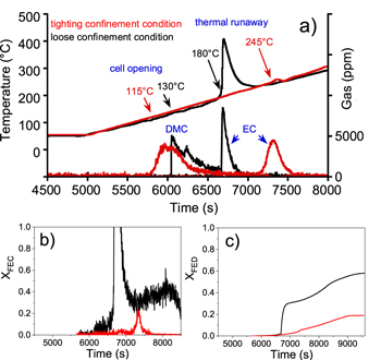
Figure 3. (a) Prototype cells surface temperature and production of dimethyl carbonate (DMC) and ethylene carbonate (EC) solvents detected from FTIR analysis as function of time during thermal stability tests. The prototype cells were subjected to a continuous ramp of 5 °C min−1 up to 300 °C under loose (black lines) and tighting (red lines) confinement conditions. Comparison of the evolution of the (b) fractional effective concentration (XFEC) and (c) fractional effective dose (XFED).
Download figure:
Standard image High-resolution imageGas analysis by FTIR showed that a lower quantity of gases was released during the test with tightly confined cell (figure 4b). CH4 and OCH2 were hardly detected. C2H4 coming from the reduction of EC31,32 was detected from 165 °C and its concentration gradually increased until the detection of the low exothermic reaction around 245 °C, temperature at which other gases (CO, CO2, HF and POF3) were also detected. The very weak detection of gases coming from linear carbonates reduction (OCH2 and CH4) and the C2H4 concentration profile confirm the difficult accessibility of the electrolyte to the surface of the negative electrode. At 245 °C, gaseous EC reacts with the oxygen released by the cathode to form CO2, CO and water, the latter promoting the formation of HF and POF3 from PF5. Without tighting confinement (Fig. 4a), larger amount of all the gases coming from electrolyte reduction, oxidation and reaction with water are detected from the beginning of the exotherm around 180 °C.

Figure 4. FTIR analysis of CO2, CO, C2H4, CH4, OCH2, HF and POF3 gas as a function of time during thermal stability tests on reference prototype cells under (a) loose and (b) tighting confinement conditions.
Download figure:
Standard image High-resolution imageFire induced toxic-gas models of ISO 13571 applied on these experiments showed that, for asphyxiant gases, within the enclosure inside our testing device, the critical threshold value of XFED (Fig. 3c) equal to 1 was never reached for both configurations. Of course, it shall not be taken for granted that none of those cells configurations would not lead to any toxic threat to people from asphyxiant gases, as this observation only deals with the test configuration enclosure, and subsequently do not directly reflect a plausible scenario of interest in field use of these cells in given application. More interestingly therefore is the fact that maximal XFED value is significantly lower for test on tightly confined cells, as compared to loosely confined cell test configuration owing to the fact that the production of CO is significantly lower in this condition (Fig. 4). Regarding irritant gases, the critical threshold value of fractional effective concentration, XFEC (Fig. 3a), is never reached for test on confined cells contrary to the test performed without tighting confinement, confirming a real safety advantage on pouch cell anti-swelling mounting arrangement. Whereas XFEC profile in loosely confined case is driven by the production of fluorinated compounds (HF, POF3) and formaldehyde (OCH2), it is only governed by the release of fluorinated compounds (HF, POF3) in the case of the test on tightly confined cells. These modeling results confirmed the positive effect of a cell mounting inducing tighting confinement as a result of module design on the thermal runaway and induced off-gas toxicity.
Influence of the electrolyte composition
DSC measurements performed on graphite-based negative electrode film with different electrolyte compositions had showed, in a previous study,17 a synergistic effect of VC (2 wt%) addition and partial substitution of LiPF6 (1/3 M) by LiFSI resulting in an improvement of the thermal behavior, i.e. a shift of the SEI related exothermic reactions to higher temperature (+50 °C) and a decrease of the heat energy release of more than 30%. Considering these encouraging results, shown at SEI level, thermal stability tests on loosely confined pouch prototype cells with same graphite electrode and electrolyte compositions were performed.
The reference and VC containing electrolyte cells opening (Fig. 5a), characterized by linear carbonates emission, occurred at the same temperature of 130 °C, whereas the thermal runaway phenomenon accompanied with gases (EC, CO, CO2, CH4, C2H4, OCH2, HF and POF3) release (Fig. S1 is available online at stacks.iop.org/JES/167/090513/mmedia) of the prototype cells activated with the VC containing electrolyte occurred at a higher temperature of 20 °C compared with the reference electrolyte prototype cell. The nature and the quantity of emitted gases were close for both types of cells (Fig. 6), indicating that reaction mechanisms are similar. Nevertheless, certain trends are observed for VC containing electrolyte prototype cells such as a relatively lower emission of EC and gaseous products coming from the reduction of the carbonates as well as a higher emission of CO2. It is supposed that, upon heat-induced secondary SEI generation,17 the remaining VC additive reduces before solvents, lowering related gas emission. Additionally, the delayed thermal runaway gives EC time to react with oxygen released from NMC, leading to lower EC and higher CO2 emissions. HF and POF3 profiles are similar for both prototypes, indicating water presence related LiPF6 salt degradation mechanisms are logically not affected by VC addition.
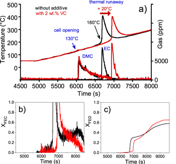
Figure 5. (a) Surface temperature and production of DMC and EC solvents of prototype cells containing a reference electrolyte with (black) and without 2 wt% VC (red) as function of time during thermal stability tests performed under a continuous ramp of 5 °C min−1 up to 300 °C and a loose confinement condition. Comparison of the evolution of the b) fractional effective concentration (XFEC) and (c) fractional effective dose (XFED).
Download figure:
Standard image High-resolution image
Figure 6. Gas amount emitted during thermal stability tests of prototype cells containing a reference electrolyte with (red) and without (black) 2 wt% VC, under loose confinement condition.
Download figure:
Standard image High-resolution imageRegarding toxicity assessment, the critical threshold value of XFED (Fig. 5c) obtained in our test conditions equal to 1 was never reached whatever the electrolyte composition, indicating the low contribution of the asphyxiant gas. CO was the only asphyxiant gas detected during the thermal stability test on these prototypes. Figure 5b shows that fractional effective concentration XFEC rises over the critical threshold value when the thermal runaway occurs, after 111.2 min for prototype with reference electrolyte and after 115.6 min for prototype with VC electrolyte. These results are consistent with the thermal profiles. FEC profile is driven by the production of fluorinated compounds (HF, POF3) and formaldehyde (OCH2), whatever the electrolyte composition. The improvement of the thermal behavior in terms of onset thermal runaway temperature in presence of VC, detected from DSC measurements17 (+50 °C) is then confirmed, though to a lesser extent (+20 °C), at a larger scale, in thermal tests on 0.6 Ah pouch cells. The effect of the presence of an additive acting on SEI formation demonstrates the predominant role of the negative electrode/electrolyte interface in the early stages of the thermal runaway.
This 20 °C onset thermal runaway temperature shift detected in case of VC containing electrolyte prototype cells is maintained when LiPF6 salt is partially substituted by LiFSI (Fig. 7a). In addition to gases coming from electrolyte solvents and LiPF6 salt decomposition (Fig. S2), other gases such as SO2, NO and HCN are likely to be emitted from LiFSI decomposition/combustion.20 In the experiments of this study, SO2 (Fig. 7b) was detected in a low amount (few milligrams) compared with LiFSI initial weight in the electrolyte (128 mg), whose total transformation (combustion and decomposition) would lead to 87 mg of SO2. As already observed by DSC, the reduction of LiFSI into LiSO2N(Li)SO2Li salt and LiF33 is favored over its combustion/decomposition at higher temperature, explaining this low proportion of SO2. As shown in Fig. 7d, the critical threshold value of XFED equal to 1, in this case again, is never reached whatever the electrolyte composition, indicating the low contribution of the asphyxiant gas in toxicity assessment. For 1 M LiPF6-based reference electrolyte prototype, CO (Fig. S2) was the only asphyxiant gas that contributed to the FED indice whereas for LiPF6/LiFSI-based electrolyte, XFED profile was largely driven by the production of CO with a very slight contribution of HCN, since this latter gas was emitted in very low amount (<1 mg in total). XFEC rises over the critical threshold value after the same time for both prototypes (Fig. 7c). For reference electrolyte prototype, XFEC profile was driven by the production of fluorinated compounds (HF, POF3) and formaldehyde (OCH2). For LiPF6/LiFSI-based electrolyte prototype cells, SO2 and OCH2 contributed to XFEC profile. Fluorinated compounds also contributed, but, to a lesser extent, since the maximal concentration peak of these gases was around 2 to 2.5 times lower than those observed with reference electrolyte prototype cells. These results lead to the conclusion that replacing 1/3 M LiPF6 by LiFSI does not significantly modify the thermally-induced toxicity threat from potentially released asphyxiant and irritant gases as a result of thermal runaway of concerned cells.
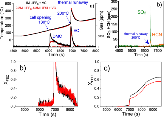
Figure 7. (a) Surface temperature and production of DMC and EC solvents of prototype cells with a reference electrolyte +2 wt% VC (black) and with a 2/3 M LiPF6−1/3 M LiFSI + 2 wt% VC electrolyte (red) as function of time during thermal stability tests performed under a continuous ramp of 5 °C min−1 up to 300 °C and a loose confinement condition. (b) Concentration profiles of SO2 and HCN for the prototype cells containing a 2/3 M LiPF6−1/3 M LiFSI + 2 wt% VC electrolyte. Comparison of the evolution of the (c) fractional effective concentration (XFEC) and (d) fractional effective dose (XFED).
Download figure:
Standard image High-resolution imageInfluence of the separator
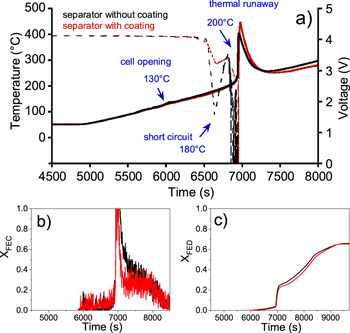
Thermal stability tests on prototype cells containing VC electrolyte and polyolefin PP/PE/PP separator with or without ceramic coating were performed. Whichever the type of separator, a first sudden voltage drop (Fig. 8a) was observed at 180 °C due to successive melting of the polyolefin layers, and then a second voltage drop until 0 V occurred during the thermal runaway at 200 °C. The nature of emitted gases and the quantity of CO2, CO, CH4, C2H4 (Fig. S3), and carbonates (DMC, EMC, EC) released were similar for both types of cells. The total quantity of fluorinated compounds (POF3 and HF) as well as of OCH2 was found to be lower for ceramic-coated separator prototype cells (12, 11 and 14 mg vs 26, 20 and 22 mg respectively). This difference can be explained by the fact that fluorinated compounds react with the ceramic part of the separator through acid-base reactions. The maximal concentration peak of HF, POF3 and OCH2 was respectively 5.8, 3.7 and 3.9 times lower than those measured with prototype cells without ceramic coating. Although XFEC value rises over the critical threshold value after the same time for both prototypes (Fig. 8b), it is noticeable, in the case of prototype cells with ceramic coating, that a significantly lower room flow rate would be required to bring XFEC value inferior to one. XFED equal to 1 was never reached in our test conditions whatever the separator composition, indicating again the low contribution of the asphyxiant gas (Fig. 8c) in toxicity assessment with CO as the only asphyxiant gas detected during the thermal stability test on these prototypes.
Figure 8. (a) Surface temperature and production of DMC and EC solvents solvents of prototype cells containing a reference electrolyte + 2 wt% VC and a separator without (black) and with (red) ceramic coating, as function of time during thermal stability tests performed under a continuous ramp of 5 °C min−1 up to 300 °C and loose confinement condition. Comparison of the evolution of the (b) fractional effective concentration (XFEC) and (c) fractional effective dose (XFED).
Download figure:
Standard image High-resolution image
Conclusions
The role of confinement in terms of interactions with the enclosed cell, electrolyte composition and separator coating on thermal stability and thermally induced off-gas toxicity of 0.6 Ah NMC 111/graphite prototype cells under abuse conditions has been accurately assessed by making use of a customized device equipped with a FTIR spectrometer for gas analysis. The main results are summarized in Table I. Obtained experimental data were used for comparative thermal behavior and related toxicity assessments of cells of various compositions and under two modes of cell mounting by use of cell enclosure providing tighting or loose confinement. State-of-the-art fire safety international standard ISO 13571:2012, was used for the gas toxicity assessment.
Table I. Summary test cells characteristics, associated test configurations and key data relation to thermal and chemical responses from performed thermal stability tests.
| Characteristics of cell prototype | Cell confinement | Phenomenon | Thermal characteristics | Detected gases |
|---|---|---|---|---|
| 1 M LiPF6, PP/PE/PP separator | Loose | Cell opening | Detected at 130 °C | DMC, EMC |
| Thermal runaway | Onset T: 180 °C | EC, CO2, CO, CH4, C2H4, OCH2, HF, POF3 | ||
| Max. peak T: ∼420 °C | ||||
| Tighting | Cell opening | Detected at 115 °C | DMC, EMC, C2H4 from 165 °C | |
| Thermal runaway | Onset T: 245 °C Max. peak T: 260 °C | EC, CO2, CO, HF, POF3, CH4, OCH2 | ||
| 1 M LiPF6 + 2 wt% VC | Loose | Cell opening | Detected at 130 °C | DMC, EMC |
| PP/PE/PP separator | ||||
| Thermal runaway | Onset T: 200 °C Max. peak T: ∼420 °C | EC, CO2, CO, CH4, C2H4, OCH2, HF, POF3 | ||
| 2/3 M LiPF6−1/3 M LiFSI + 2 wt% VC PP/PE/PP separator | Loose | Cell opening | Detected at T = 130 °C | DMC, EMC |
| Thermal runaway | Onset T: 200 °C Max. peak T: ∼420 °C | EC, CO2, CO, CH4, C2H4, OCH2, HF, POF3, SO2, HCN | ||
| 1 M LiPF6 + 2 wt% VC ceramic coating separator | Loose | Cell opening | Detected at 130 °C | DMC, EMC |
| Thermal runaway | Onset T: 200 °C Max. peak T: ∼440 °C | EC, CO2, CO, CH4, C2H4, OCH2, HF, POF3 |
This study showed a tangible attenuation and delay (from 180 °C to 245 °C) of the thermal runaway phenomenon when prototype cells are kept tightly confined upon thermal test, thus prevented from swelling. This safer behavior is explained by the limited electrolyte accessibility to the surface of both electrodes, induced by the earlier linear carbonate solvents departure and the electrode covering by the melted separator. All gases stemming from the reduction and oxidation of electrolyte solvents as well as the lithium salt degradation with water are detected in a much lower amount, so that anti-swelling arrangement of such cells in module is shown as a favorable design to limit thermally induced toxic gas release under abuse conditions, whatever the type of feared physiologic effect (asphyxiant or irritant character).
Regarding the electrolyte composition, the presence of an SEI reinforcing additive as VC, proved to be beneficial in delaying the onset temperature of the thermal runaway and associated toxic gas release threat since a shift of +20 °C was observed. This demonstrates the predominant role of the negative electrode/electrolyte interface in the early stages of thermal runaway. The results also showed that the thermal response profile was identical when 1/3 M LiPF6 salt was partially substituted by LiFSI, while the nature and the quantity of gases released were somewhat different. However, LiFSI related SO2 emission replaces part of fluorinated compounds (from LiPF6) and HCN amount (issuing from the presence of the imide) is so small that the irritant and asphyxiant gases concentrations remain almost identical, which in turn does not significantly change the toxicity hazard.
Finally, ceramic coating of the polyolefin tri-layer separator has shown to have a beneficial effect regarding global toxicity, since the maximal concentration peak of fluorinated compounds and formaldehyde were significantly reduced for ceramic-coated separator prototype cells as compared to the case of cells containing conventional non-coated polymer separator. This difference can be explained by the fact that fluorinated compounds react with the ceramic part of the separator.
This study highlights that some improvements regarding safety can be achieved through appropriate component selection and cells integration design into a module/pack level.
Acknowledgments
The support from the Association Nationale de la Recherche et de la Technologie (ANRT, France) is gratefully acknowledged. The authors are grateful to Michel Armand for fruitful discussions.