
Abstract
Lead-Carbon hybrid ultracapacitors have attracted attention in recent times due to high power density and remarkably long cycling stability. Herein, we report bio-waste orange peel derived B, N doped porous carbons as negative electrode active material for Pb-C hybrid ultracapacitors. B, N doped porous carbons are obtained from orange peel using boric acid by carbonization at 800 °C. B, N doped porous carbons contain about 1.22% of boron, 2.89% of nitrogen. These porous carbons exhibit 866 F g−1 capacitance at 1 A g−1 current density in potential range between the −0.4 V to 0.2 V. Pb-C hybrid ultracapacitors assembled with these carbons as the negative electrode and in situ formed PbO2 as a positive electrode can deliver capacitance of 192 F g−1 at 10 A g−1 and stable over 10,000 cycles. The superior electrochemical performance of lead-carbon ultracapacitor is due to the boron and nitrogen doping into the carbon, which increases the hole density and electron carrier, respectively and subsequently enhances the charge storage property. The significant improvement in capacitance of the ultracapacitor electrode of Pb-C hybrid ultracapacitors presented here opens up a new realm of possibilities for the lead-carbon ultracapacitor development and will contribute directly towards improving the energy and power density of the system.
Export citation and abstract BibTeX RIS

This is an open access article distributed under the terms of the Creative Commons Attribution Non-Commercial No Derivatives 4.0 License (CC BY-NC-ND, http://creativecommons.org/licenses/by-nc-nd/4.0/), which permits non-commercial reuse, distribution, and reproduction in any medium, provided the original work is not changed in any way and is properly cited. For permission for commercial reuse, please email: oa@electrochem.org.
Lead-acid batteries (LAB) operating at high-rate partial state of charge cannot accept charge at high currents, thereby increases the sulfation at the negative electrode and reduces cycle life.1–4 In order to improve the electrochemical performance of LAB, researchers have been extensively used carbon diluents (0.01 to 5 wt%) such as high surface area carbons, graphenes, carbon nanotubes, etc. to negative active material (NAM) to improve electronic conductivity and active material utilization of the paste.5–10 High surface area carbons may occupy in the pores of the active material and improve the electrolyte access into the interior of the electrode. Thereby facilitates the conversion of PbSO4 to Pb at the negative electrode.5–10 In another way to improve the performance of the LAB is to replace the negative electrode completely with carbon type electrochemical double-layer capacitor (EDLC) electrodes. The energy storage principle of such a lead-carbon (Pb-C) hybrid device can be explained by faradic redox reaction that occurs at the positive PbO2 electrode and EDLC charge storage process that takes place at the carbon negative electrode.11–19 Pb-C hybrid ultra-capacitors (HUCs) have attracted attention in the field because there is no sulfation occurs at the negative electrode. It delivers more power density (>10 kW kg−1) and long cycle life (>1,00,000 cycles) compared to a LABs, which enables them to find potential applications in the high surge currents and rapid charge-discharge cycle requirements such as start-stop, electric vehicles, and grids, etc.20–31
In Pb-C HUCs, the PbO2 electrode has higher capacitance compared to the carbon negative electrode due to the faradaic process. The commercial positive electrode cannot be used in Pb-C HUCs because of the huge capacitance difference between the PbO2 and carbon electrode. Hence, an electrodeposited or thin layer of in situ formed PbO2 is employed as a positive electrode in Pb-C HUCs. In this work, in situ formed PbO2 in H2SO4 is used as a positive electrode. Lead carbon HUCs assembled with commercially available carbon (Surface area = 1512 m2 g−1) on graphite sheet exhibits specific capacitance of 102 F g−1 with 92% of faradaic efficiency at 1.6 mA cm−2 in the potential range between 1.0 and 2.3 V using 6 M sulfuric acid electrolyte.29 In another strategy, electrodeposited thin film PbO2 on Ti/SnO2 substrate combined with activated carbon (Surface area = 1700 m2 g−1) in 4.5 M sulfuric acid shows 3000 cycles with 83% capacity retention. The cells show the energy and power densities of 7.8 Wh kg−1 and 258 W kg−1, respectively.30 Precoating of SnO2 on the Ti sheet facilitates the electrodeposition of PbO2. PbO2 electrodeposited on three-dimensional porous titanium sheet (3D-Ti/PbO2) combined with activated carbon delivers 49.4 Wh kg−1 energy density and 433.2 W kg−1 power density with a specific capacitance of 135.2 F g−1 at 0.9 A g−1 and stable for 1000 cycles. The energy and power densities of Pb-C HUCs are enhanced due to the high active material utilization of the PbO2 electrode.31 A brief comparison table has given in Supplementary Table I (available online at stacks.iop.org/JES/167/090512/mmedia).29–34 In the literature, it has been found that most of the work is devoted to positive electrode architecture in Pb-C HUCs to improve active material utilization. Very little attention has been given to the negative electrode design of these systems.
In this work, Pb-C HUCs have fabricated by using porous activated-carbon-derived from the orange peel (BNC) as negative active material and in situ activated PbO2 electrode as a positive electrode in 4.5 M sulfuric acid electrolyte. Electrochemical performances of Pb-C HUCs have been measured by cyclic voltammetry (CV), Impedance spectroscopy (EIS), and galvanostatic-charge-discharge studies, found to be superior to many of these literature reports.
Experimental
Synthesis of B, N doped porous carbon (BNC)
B, N doped porous carbons (BNC) have been prepared from orange peel by treating with boric acid followed by carbonization in a nitrogen environment. In this process, the bio-waste orange peel was first dried at 80 °C and crushed into the powder (Step-1). 10 g of orange peel powder was stirred in 30 ml of 0.1 M. boric acid solution for 3 h at 60 °C, followed by drying in a vacuum oven at 80 °C for 24 h. The obtained sample was carbonized by using tubular furnace (Thermoconcept, Germany) at different temperatures, such as 600 °C, 800 °C and 1000 °C for 3 h in a nitrogen atmosphere. The obtained powders were treated with 3 M HCl solution and rinsed with deionized water for several times to remove impurities from the sample and dried in a vacuum oven for overnight at 80 °C, to get B, N doped porous carbons. Hereafter, B, N- doped porous carbons carbonized at different temperatures are referred to as BNC-600, BNC-800 and BNC-1000. Nitrogen-doped carbons were obtained without boric acid treatment under similar thermal and environment treatment and are labeled as NC-600, NC-800 and NC-1000 (NC- Nitrogen-doped carbon). The schematic of BNC and NC synthesis is shown in Supplementary Figs. S1(a and b).
Physical characterizations
The physical characterizations of as-synthesized NC-800 and BNC-800 were carried out using the XRD instrument (Panalytical X'pert pro diffractometer) with Cu-Κα (λ = 1.54 Å) radiation (40 mA, 40 KV). The data was analyzed 0.02 step width over 2θ range from 10 to 70°. Raman spectroscopy carried out using the Bruker Senterra Raman microscope He-Ne laser (632.8 nm) frequency in the range of 1000–2400 cm−1. Weight loss of the material BNC material was determined by TGA using a Q600 Thermo-gravimetric analyzer under an air atmosphere in the temperature from 25 °C to 900 °C at a heating rate of 10 °C min−1. Functional group analysis was carried out by FTIR spectroscopy (Bruker Alpha–P (Germany) in the wavelength range between 600–1600 cm−1. Morphology of BNCs was characterized by the scanning electron microscopy (SEM JEOL-2011(200 KV), transmission electron microscopy (TEM-JEOL, JEM 2100FX). The specific surface area and the pore size distribution of BNC-800 have determined by using the Brunauer–Emmett–Teller (BET) method using a Micromeritics ASAP 2020 surface area analyzer. X-ray photoelectron spectroscopy (XPS) study was performed to obtain the elemental composition of the BNC material. XPS measurements were carried out using ESCA+, (Omicron nanotechnology, Oxford Instruments Plc., Germany) equipped with monochromic AlKα (1486.6 eV) X-ray beam radiation operated at 15 kV and 20 mA, binding energy was calibrated vs carbon (C1s = 284.6 eV). The XPS spectra were deconvoluted using Origin 9.0 software based on Gaussian function.
Negative electrode preparation
The negative active material slurry was prepared by using 80% of NC or BNC, 10% Polyvinylidene difluoride binder (Sigma-Aldrich), 10% of carbon black (Super-65) in N, N-Dimethylformamide (DMF) (99%, Sisco Research Laboratory Pvt. Ltd., India). This slurry was coated onto the graphite sheet current collector, dried at 100 °C for overnight under vacuum and punch into 2 cm × 2 cm area electrodes for electrochemical studies.
In situ formed positive electrode
In situ formed PbO2 electrode prepared from pure lead sheet (99.9%pure) (dimension = 2 cm × 2 cm). The lead sheet was dipped in 6 M H2SO4 solution for overnight, which results in lead-sulfate formation. Subsequently, the lead-sulfate (PbSO4) sheet was converted to lead dioxide (PbO2) by constant current charge-discharge at C/20 rate. The electrode was carefully washed with distilled water and dried at 60 °C for 6 h.20,21
Fabrication of Pb-C hybrid ultracapacitor cell
The Pb-C HUCs are fabricated by sandwiching absorbent glass mat (AGM) separator in between NC or BNC-800 electrode and in situ formed PbO2 positive electrode in 4.5 M sulfuric acid electrolyte.
Electrochemical characterizations
Electrochemical performance of Pb-C HUCs and ultracapacitors were studied by using galvanostatic charge-discharge cycling, CV and EIS studies. All these experiments were analyzed by using a cell test system (Solartron analytical, Oak Ridge, TN, USA) model 1470E coupled with an FRA model 1455A. The EIS responses were recorded within a frequency range of 1 MHz and 10 m Hz at an amplitude of 5 mV under the fully discharged condition. Further, the obtained EIS data were analyzed using Z-view software (Scribner Associates, USA). The CV and charge-discharge characteristics of BNC and CV of in situ formed positive electrode were studied by using three-electrode set up containing platinum counter electrode and a saturated calomel reference electrode in the potential range between −0.4 and 0.2 V and 0.8 to 2.2 V, respectively at various scan rates. The potential range used for the hybrid capacitor is between 1.0 V and 2.4 V at various current densities.
Results and Discussion
Structural and morphological investigation
SEM and TEM images in Figs. 1a–1b of NC-800 show agglomeration of particles having irregular shapes and sizes. BNC-800 shows a porous carbon network as shown in Fig. 1c. High magnification SEM image is shown in Fig. 1d illustrates a crumpled rough sheet-like structure with various cavitation. As expected both SEM and TEM almost converge. Figures 1e–1f confirms porous in nature and irregular pattern of layer like the structure of the BNC-800, which are in accordance with the SEM study shown in Figs. 1c, and 1d. The irregular pattern is due to the doping of heteroatoms into the carbon layers possibly changes the bond length and bond angles in the BNC-800. As structure and morphology, all BNC samples are almost identical and BNC-800 samples deliver better electrochemical performance (discussed later), hence the structural and morphological investigation is limited BNC-800 samples only.

Figure 1. (a) SEM (b) TEM of NC-800; (c), (d) SEM (e), (f)TEM images of BNC-800 with different resolutions.
Download figure:
Standard image High-resolution imageThe physical properties of the carbons studied by the Raman spectra shown in Fig. 2a show both NC-800 and BNC-800, having the disordered (D) and graphitic (G) bands. NC-800 shows 'D and G bands at 1357 and 1593 cm−1 whereas BNC-800 shows at 1355 and 1575 cm−1, respectively. The shift in G band in BNC-800 indicates B doping into the graphic domain. There is a slight change in ID/IG ratios of NC-800 and BNC-800 shows 1.01 and 1.04, respectively further confirms doping into carbon.

Figure 2. Comparison of (a) Raman, (b) XRD, (c) FTIR spectra (d) TGA of NC-800 and BNC-800.
Download figure:
Standard image High-resolution imageFigure 2b shows X-ray diffraction of the NC-800 and BNC-800 shows typical amorphous carbon peaks at 25° and 23.8°, respectively, correspond to (002) basal plane. The slight decrease in the 2θ value for BNC-800 indicates that there is little increase in the interlayer distance due to B-dopping as compared to that of NC-800, which further confirmed by the shift of (100) plane peak to 43.6° (BNC-800) from 45° (NC-800). The increase in interlayer distance is attributed to Boron doping which is bigger in size compared to carbon.35 The (002) and (100) planes reveal the noncrystalline nature of BNC-800, similar to that of activated carbon.
Further, the BNC-800 sample was examined by Fourier transmission infrared (FTIR) spectroscopy to identify the functional groups present in the material. Figure 2c shows the FTIR pattern of NC-800 and BNC-800 measured in the range between 600 cm−1 and 1600 cm−1. NC-800 shows bands at 761 cm−1 are attributed to the in-plane bending of C–O–C bonds, 851 cm−1 is due to –C=O bending, 1515 cm−1 shows C–N stretching, and bands in between 1128 to 1230 cm−1 confirms the presence of C–H bending groups (methyl). In BNC-800, the peaks at 1414 cm−1 and 3738 cm−1 correspond to stretching and bending modes of the B–N group. Peaks at 1220 cm−1 and 1145 cm−1 confirm the presence of the B–C groups, correspond to stretching and in-plane bending modes of B–C bond. The broad and sharp peak at 1502 cm−1 is attributed to the presence of nitrogen as C–N and N–O groups. The presence of the peaks centered at 761 cm−1 and 696 cm−1 are due to the in-plane bending of C–O–C and O–B–O bonds, respectively.
The thermal stability of NC-800 and BNC-800 was studied by TGA in the temperature between 25 °C and 900 °C as shown in Fig. 2d. Initial 12% of weight loss up to 200 °C is observed due to the removal of moisture from the sample. This is followed by the removal of functional groups up to 400 °C for NC-800 and 500 °C for BNC-800 samples. The decomposition of boron, nitrogen, and carbon starts after these temperatures and complete decomposition of NC-800 and BNC-800 samples occur at 580 and 720 °C, respectively. BNC-800 shows maximum weight loss compare to the NC-800 due to the removal of Boron containing functional groups. The specific surface area calculated from the BET adsorption isotherm shown in Supplementary Fig. S2a is 193 m2 g−1, indicating a type-IV isotherm. The pore size distribution of BNC-800 sample calculated from Supplementary Fig. S2b are about 2–4 nm.
XPS results confirm the boron and nitrogen-doped into the carbon material as shown in Fig. 3. 1.22% of Boron and 2.89% of nitrogen has been doped in BNC-800 material. The de-convoluted C1s spectra consist of different peaks: C–C, C–N, C–B, C=O C–O–B and, –COOH at binding energies 284.75, 285.56, 283.97, 287.24, 289.23 and 291.32 eV, respectively as shown in Fig. 3a. The C–B, C–N band at 285.56 and 283.97 eV, respectively further confirm the presence of boron and nitrogen. Deconvoluted O1s spectra (Fig. 3b) show carbonated oxygen, –COOH (acidic), alcoholic (C–OH), adsorbed oxygen bands at binding energies of 531.53, 532.20, 533.66 eV and 536.72 eV, respectively. B1s spectra (Fig. 3c) show B–N, B–C and B–O bands at binding energies 190.61, 191.63 and 193.02, respectively. Figure 3d implies the N1s spectrum consists of bands at 398.7, 400.15, 401.78 and 404.31 eV due to pyridinic (Pyd-N), pyrrolic (Py-N), graphitic (Gr-N) and oxygenated (Oxy-N) nitrogen bands, respectively. Percentage analysis of different boron bonds and nitrogen functionalities in BNC-800 is shown in Figs. 3e–3f. All these XPS data confirm the successful incorporation of Boron and nitrogen into carbon, align with FTIR data presented in Fig. 2c.

Figure 3. XPS spectra of BNC material for (a) C1s, (b) O1s, (c) B1s, (d) N1s (e), (f) Percentage analysis of boron and nitrogen.
Download figure:
Standard image High-resolution imageElectrochemical performance of NC-800 and BNC-800 electrode
The composite electrodes were tested in the voltage range between −0.4 to 0.2 V because these electrodes are used as negative electrodes in lead-carbon hybrid ultracapacitors which is the potential window for lead negative electrodes in a lead-acid battery. Charge storage property of the NC-800 and BNC-800 electrodes was studied by CV at 1 mV s−1 scan rate shows a rectangular shape (Fig. 4a) is owing to its pure capacitive nature in the potential range −0.4 V to 0.2 V. The charge storage property of the NC and BNC electrode is due to the electrical double layer formation at the electrode and electrolyte interface, which is purely an EDLC type. NC-800 shows the less specific charge compare to the BNC-800, hence less capacitance. As the scan rate increases (100 mV.s−1) the rectangular shape of the CV curve deviated to a quasi rectangular shape (Fig. 4b) is due to slow kinetics at high scan rate and more overpotential. As the scan rate increases, the area under the curve increases, subsequently the capacitance increases. The specific capacitance of BNC electrodes (BNC-600, BNC-800 and BNC-1000) obtained from galvanostatic charge-discharge curves at 5 A g−1 current density are shown in the supplementary Fig. S3. BNC-800 delivers the highest specific capacitance of 605 F g−1 which is much higher in relation to BNC-600 (234 F g−1) and BNC-1000 (267 F g−1) electrodes (Supplementary Table II). The decrease in the specific capacitance of BNC-1000 is due to a higher carbonization temperature of 1000 °C which causes more agglomeration of particles, reduced porosity subsequently inhibits the passage of electrolyte ions into the electrode and charge storage. In BNC-600, the temperature may not sufficient enough to form conducting networks in the active material, delivering less specific capacitance. Hence, all the electrochemical studies presented here are limited BNC-800 samples only.
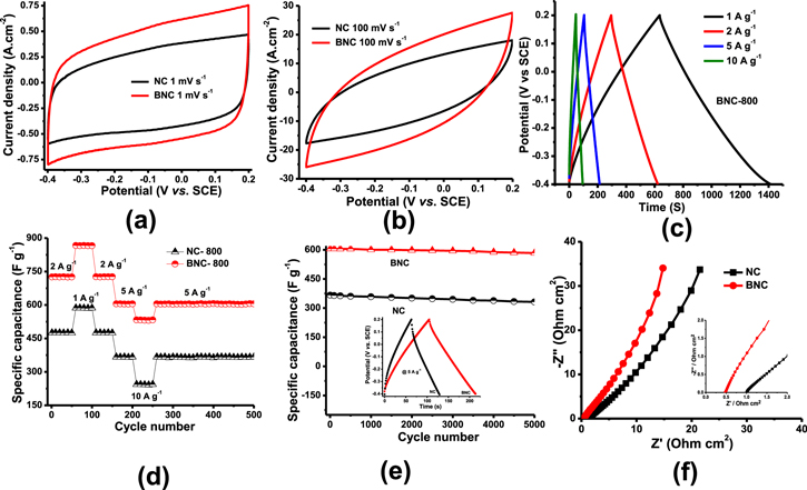
Figure 4. Electrochemical studies of NC-800, BNC-800 material by the three-electrode system (vs SCE), (a) Slow scan cyclic voltammetry (1 mV s−1), (b) high scan rates of CV 100 mVs−1 (c) Galvanostatic charge-discharge curves at different current densities (C-Rate performances) (d) C-rate performance data of NC-800, BNC-800 electrodes at different current densities as shown in the figure (e) Cycle life study of NC-800 and BNC-800 in the voltage range between −0.4 to 0.2 V (f) Electrochemical impedance spectroscopy of NC-800, BNC-800 samples (inset) shows the high-frequency region of EIS.
Download figure:
Standard image High-resolution imageThe specific capacitance of the BNC-800 obtained from galvanostatic charge-discharge curves with different current densities as shown in Fig. 4c. As the current density increases from 1 to 10 A g−1 charge-discharge curves convert to a symmetrical triangular shape and no voltage drop (IR) occurs. The specific capacitances obtained from charge-discharge curves are 866, 726, 605 and 532 F g−1 at current densities of 1, 2, 5 and 10 A g−1, respectively. The specific capacitances NC-800 are 586, 475, 366 and 242 F g−1 at current densities of 1, 2, 5 and 10 A g−1, respectively comparatively smaller than BNC-800 composite electrodes (Supplementary Fig. S4 and Table III). The capacitance values are decreased with increasing current density in the charge-discharge curves. At low current density 1 and 2 A g−1 the electrolyte ions (H+, HSO4−) easily enters into the interior of the electrode, improves the electrochemically active material utilization and thereby increases specific capacitance. At low currents, the capacitance contribution from BNC-800 is due to pseudocapacitance and EDLC. Marginal pseudocapacitive behavior is due to the functional groups and protonation in sulfuric acid solution. At high current density, electrolyte ions cannot enter into the interior electrode. It absorbs only on the surface of the electrode and exhibits EDLC-type behavior. In sulfuric acid solution, the BNC compound easily oxidizes to form BNCO complex and contributes the capacitive behavior.35–37 BNC-800 contains pyrrolic, graphitic and pyridine functional group which enhances capacitive behavior. C-rate performances at different current densities as shown in Fig. 4d suggests the BNC-800 shows the good specific capacitance almost 30%–50% increase in capacity from slow (1 A g−1) to high rates (2–10 A g−1). After high rates when they have cycled at 5 A g−1 (Fig. 4d) the composite electrodes retain their capacitances. Both NC-800 and BNC-800 delivers stable specific capacitance and have 91% and 97% capacitance retention for 5000 cycles (Fig. 4e). Further EIS measured for NC-800 and BNC-800 composite electrodes during the 1st cycle (Fig. 4f) consists of a straight line, extend towards the Y-axis which is the characteristic feature of supercapacitor active materials. BNC-800 shows shows less solution resistance (0.489 Ohm.cm2) compared to NC-800 (1.008 Ohm.cm2).
To understand the charge storage property of NC-800 and BNC-800, CV curves were studied as shown in Figs. 5a–5b and supplementary Figs. S5, and S6. These curves consist of a combination of pseudocapacitive and capacitive behavior. In hybrid charge devices, the charge storage mechanism is calculated by the power law.

Where a and b were the adjustable parameters, these parameters were obtained by plotting the log ν vs log i. Charge storage kinetics depend on the b value. When b = 0.5 the process is Diffusion controlled and when b = 1, the charge storage process is capacitive in nature. Figures S4, S5e shows the b value falls in the range between 0.978–0.966 at 0.5 to 5 mV s−1 scan rate confirms the charge storage behavior is purely capacitive. The pseudocapacitive behavior in NC-800 and BNC-800 was further analyzed by the following equation.

Here i is the current density at a particular potential,  indicates the capacitive and
  shows the pseudocapacitive behavior (diffusion-controlled insertion process) in the electrode.38,39 S1 and S2 values were calculated by using this equation from Supplementary Fig. S5f and S6f. NC-800 shows a 93.3% capacitive component in comparison to 89% of BNC-800 at 1 mVs−1 scan rate (Fig. 5c–5d) is due to the incorporation of boron and related functional groups which enhances pseudocapacitances.

Figure 5. Charge storage mechanism in NC-800 and BNC-800, (a) NC-800 (b) BNC-800 CV curves of at low scan rates (0.5, 1, 2, 3, 4 and 5 mV s−1). (c) NC-800 (d) BNC-800 corresponding CVs at 1 mV s−1 shows the capacitive and pseudocapacitive contribution in the charge storage.
Download figure:
Standard image High-resolution imageElectrochemical performance studies on the positive electrode
The cyclic voltammetry of the positive electrode was examined by the three-electrode system in 4.5 M sulfuric acid at a scan rate of 2 mV s−1 (as shown in Fig. 6a) in the potential range between 0.8 V and 2.2 V vs SCE. The CV shows partial oxidation Pb+2 → α-PbO2 at 1.4 V followed by complete oxidation of Pb to β-PbO2 between 1.7 and 1.95 V vs SCE. The sharp increase in peak after 2 V is due to the oxygen evolution. The cathodic peak at 1.44 V indicates the reduction of PbO2 to PbSO4.40,41
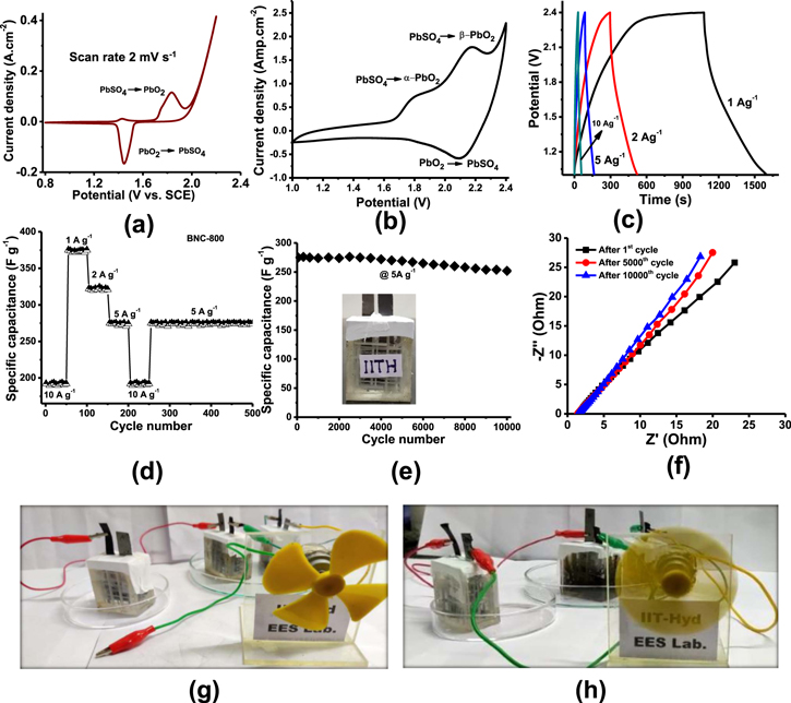
Figure 6. Electrochemical studies of Pb– C hybrid-ultra capacitor in 4.5 M. sulphuric acid electrolyte, (a) Cyclic voltammetry studies of in situ activated positive electrode examined by the three-electrode system (vs SCE) at a scan rate of 2 mV s−1 (b) Pb–C hybrid-ultra capacitor cyclic voltammetry at 2 mV s−1 scan rate, (c) Galvanostatic charge-discharge curves at various current densities, (d) C-rate performances of Pb–C hybrid-ultra capacitor at different current densities (e) Cycling study of the Pb-C HUC cell at 5 A g−1 (f) Nyquist plots of Pb-C HUC t 1st, 5000th and 10000th cycle in the rage if 1 MHz to 10 mHz. Illustration of a toy fan operated with 3 charged Pb-C hybrid ultracapacitors connected in series (g) without and (h) with electrical connections.
Download figure:
Standard image High-resolution imageElectrochemical performance of Pb-C Hybrid ultracapacitor
The CV of Pb-C HUC was studied in the voltage range between 1.0 and 2.4 V. As shown in Fig. 6b, two distinct anodic peaks at 1.78 V and 2.15 V are observed due to formation α-PbO2 from the inner PbO and PbSO4, β-PbO2 from PbO. PbSO4, respectively. The reduction occurs at 2 V, which corresponds to PbSO4 formation.
Pb-C HUC galvanostatic charge-discharge curves of BNC-600, BNC-800, BNC-1000 in 4.5 M sulfuric acid medium at 5 A g−1 current density deliver capacitance of 50, 275 and 171 F g−1, respectively as shown in the Supplementary Fig. S7 and Supplementary Table IV. To evaluate the specific capacitance of the Pb-C HUC (BNC-800), charge-discharge measurements were performed in the voltage range between 1–2.4 V at different current densities (1, 2, 5, and 10 A g−1) at room temperature as shown in Fig. 6c. After 2.4 V more oxygen evolution occurs at the positive electrode, which may cause cell failure. Hence the upper cut off voltage was limited to 2.4 V. The capacitances obtained from charge-discharge curves are 371, 322, 275 and 192 F g−1 correspondings to current densities of 1, 2, 5 and 10 A g−1 respectively.
The obtained results confirm the Pb-C hybrid ultracapacitor discharge curves are a combination of capacitor and battery analog. These curves are neither symmetrical nor triangular and behave like a hybrid ultracapacitor. The voltage drop obtained at the initial stages of discharge is IR drop. A low IR drop is obtained at all discharge curves, indicating less resistance in the HUC. After the IR drop, the voltage profiles are non- linear. The voltage profiles consist of capacitive and battery behavior. Capacitive nature is attributed to the negative BNC-800 electrode and battery behavior is due to the PbO2 positive electrode.
Cycle life studies of BNC-600, BNC-800, BNC-1000 in 4.5 M sulfuric acid medium as shown in the supplementary Fig. S8. Figure 6e shows the cycling stability of the Pb-C hybrid ultracapacitor (BNC-800) at 5 A g−1 in the potential window between 1.0 and 2.4 V. Pb-C HUC show ∼92% capacitance retention after 10000 charge-discharge cycles. Stable capacitance is obtained due to the porous nature of the BNC material, easy access of the electrolyte ions into the electrode, which is having the charge storage property. Further stable electrochemical behavior Pb-C hybrid ultracapacitor was analyzed by EIS, as shown in Nyquist plots of Pb-C hybrid ultracapacitor after1st cycle, 5000th cycle and 10,000 cycles in Fig. 6f. The ohmic resistance (RS) of Pb-C HUC during 1st, 5000th and 10,000 cycles was 1.59, 1.48 and 1.44 ohm. cm2, respectively. The Ohmic resistance which is the combination of electrolyte resistance, intrinsic resistance of the substrate and contact resistance between the current collector and active material which is increased little during the 10000th cycle.
Three Pb-C HUC cells after charging up to 2.4 V/cell were connected in series and then coupled to a toy fan. The photographs of the toy fan with and without electrical connection are shown in Figs. 6g–6h. The toy fan works well when it is connected to the Pb-C HUCs.
In overall, BNC-800 delivers high capacitance is due to both pseudocapacitance and EDLC behavior of the material. Partial Pseudo capacitance arises from the functional groups and protonation in high concentrated 4.5 M sulfuric acid solution. At high current density (5–10 A g−1), electrolyte ions absorb only on the surface of the electrode and exhibit EDLC-type behavior. BNC compound easily oxidizes in sulfuric acid solution, forms BNCO complex and contributes the capacitive behavior. The pyrrolic, graphitic and pyridine functional group present in the BNC sample further enhances capacitive behavior.
The capacitance of lead-carbon hybrid ultracapacitor is due to both capacitive and battery type behavior. Capacitive nature is attributed to the negative BNC electrode and battery behavior is due to the PbO2 positive electrode.
Postmortem analysis of lead dioxide electrode
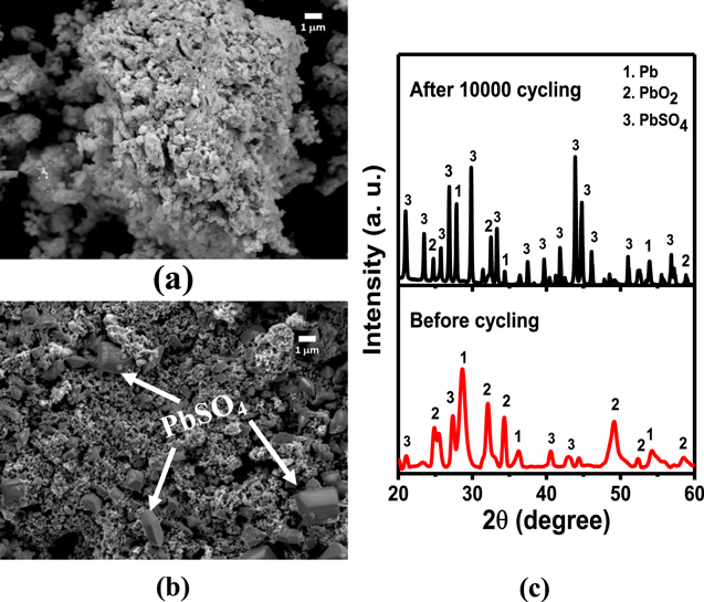
Figures 7a and 7b shows SEM images of the PbO2 electrode before cycling and after 10000 cycling's, respectively. Figure 7b shows big polygon type PbSO4 particles are slowly evolving after 10000 cycles. Still, the surface is occupied with a majority of PbO2 particles (small particles). This is further supported by the XRD pattern shown in Fig. 7c which shows PbSO4 formation after 10000 cycles. The Pb peaks are attributed to the inner non-active part of the lead sheet. The minor change in the structure and morphology of the electrode confirms better and longer cycling stability of the PbO2 electrode in lead-carbon hybrid ultracapacitors. It may be attributed to a thin layer of in situ formed PbO2 electrode, which restricts the crystal growth of PbSO4 in the interior of the positive electrode. As a result, there is not much capacitance fade of Pb-C hybrid ultracapacitor during successive 10000 s of charge-discharge cycles.
Figure 7. SEM images of PbO2 electrode (a) before cycling, (b) after cycling, (c) XRD pattern of PbO2 electrode before cycling and after cycling as indicated in the view graph.
Download figure:
Standard image High-resolution image
Conclusions
B, N doped porous carbons are synthesized from bio-waste orange peel by treating with a boric acid solution followed by carbonization at 800 °C. Boron and nitrogen in porous carbon exhibit partial pseudo-capacitive as well as EDLC behavior. BNC-800 shows a specific capacitance of 532 F g−1 at 10 A g−1. Pb-C hybrid ultracapacitors developed with an activated lead sheet as a positive electrode and BNC-800 as a negative electrode show specific capacitance 371 F g−1 at 1 A g−1. NC-800 composite electrodes synthesized under similar thermal conditions shows 30%–50% lower capacitance than BNC-800 composite electrodes. This clearly indicates B doping partially enhances the capacitance of the composite electrode. Pb-C HUCs assembled with BNC-800 as the negative electrode and PbO2 as a positive electrode can deliver capacitance of 371 F g−1 at 1 A g−1 to192 F g−1 at 10 A g−1 and stable over 10,000 cycles. Overall the improved specific capacitance of material is due to the presence of the heteroatoms exhibits the pseudo-capacitance, porous carbon shows the EDLC property. The porous nature of carbon material makes easy interaction of electrolyte ions with the active site as well as an activated thin film of the PbO2 layer which results in proper charge balance in the cell. Given the availability of raw material, cost and safety, lead-carbon HUC will play an important role in future energy storage.
Acknowledgments
Sadananda Muduli acknowledges MHRD, Govt. of India for fellowship. Financial support for this project work from the Clean Energy Research Initiative (CERI) under the Department of Science and Technology (DST), Govt. of India (Project Code: DST/TM/CERI/C141) is gratefully acknowledged. We thank P. Vijay Kumar, IIT Hyderabad, for TGA and FTIR spectroscopy analysis and S. Upender of IIT Hyderabad for TEM support.