
Abstract
Reduced safety of conventional organic electrolyte (OE) lithium-ion batteries (LIBs) during abusive failure conditions pose a technical barrier and the state of uncertainty in the market penetration of electrification of vehicles and stationary storage. To address this, we report nonflammable inorganic liquid electrolyte LiFePO4/Graphite (LFP/G) batteries for commercial high energy/power applications. The inorganic electrolyte (IE) is prepared by solvating the molten LiAlCl4 salts using liquid/gaseous xSO2 (x = 1 to 22 moles SO2, proprietary formulae is used) which shows remarkably high Li+ ion conductivity of 121 mS cm−1 at 22 °C. IE LFP/Li half-cell exhibits outstanding rate capability up to 8 C with the capacity of 74 mAh g−1 at room temperature (RT). For the first time, IE-based commercial prototype LFP/G prismatic cells with the capacity of 1.08 Ah shows ultrahigh longevity (50,000 cycles at 2 C up to 20% residual capacity) with coulombic efficiency of ∼99.99% and constant internal resistance at RT. We also demonstrate depth of discharge up to 0 V for 150 cycles using IE LFP/G cells at RT, which shows comparable cycling stability of cells which are discharged to 2.5 V, in contrast to OE LIBs. Further, the capacity retention is improved by 5% using dip-coating process of positive electrodes.
Export citation and abstract BibTeX RIS

This is an open access article distributed under the terms of the Creative Commons Attribution Non-Commercial No Derivatives 4.0 License (CC BY-NC-ND, http://creativecommons.org/licenses/by-nc-nd/4.0/), which permits non-commercial reuse, distribution, and reproduction in any medium, provided the original work is not changed in any way and is properly cited. For permission for commercial reuse, please email: oa@electrochem.org.
Among several electrochemical energy storage systems, a lithium-ion battery (LIB) has been promising energy storage device to power consumer electronics, electric vehicles (EVs) and to use it in stationary grid energy storage systems.1–6 Besides being expensive, a major setback is being realized in LIB for EVs and grid applications owing to flammability/safety issues of conventional organic electrolytes (OEs) in lithium-ion batteries (LIBs) caused by internal/external shorting, sluggish electrochemical kinetics at subzero temperature and poor longevity.6–13 The poor longevity arises mainly from the fact that the cell behavior in conventional organic electrolytes is not predictable after 80 or 70% of residual capacity is achieved and the internal resistance rises unpredictably and thus results in power losses. This is the reason, why traditionally cycle life is limited to relatively high capacities. However, the rising internal resistance is not an issue with the inorganic electrolyte (IE) and thus cycle life is used without limiting to a certain capacity. Several attempts have been demonstrated to enhance the flame retardancy of OEs such as adding flame retardant additive to OEs,14–16 ionic liquids (ILs) as a co-solvent/solvent for OEs,17,18 however, it is been still challenge to realize the desired electrochemical cell and performance.19 Apart from advantages of non-combustible and wide electrochemical potential of ILs, it suffers from low ionic conductivity at room temperature (RT) owing to high viscosity.17–19 In recent times, a great amount of time devoted towards developing solid electrolytes, however, it is also suffering from lower bulk ionic conductivity at RT, challenges in interfacial stress, resistance and contact between the electrodes and solid electrolytes which hinders the realization of solid-state battery in commercial applications.20–23 In addition, the researchers are also made great attempt to develop aqueous LIB based on the water-in-salt concept24,25 using a non-flammable electrolyte, however, the reduced efficiency leads to short cycle numbers. Adding to that, the liquid electrolyte has more flexibility to design the electrochemical cell than the cells with solid-state electrolyte. Thus, it would be of great interest of research to develop liquid electrolyte which would have the advantages of low cost, non-flammability, wide operation temperature range compatibility with the electrode materials and Lithium-metal anode for lithium-metal batteries.
In 1988, Foster et al.26 reported an alternative liquid inorganic electrolyte consisting of molten LiAlCl4 salt and solvated by liquid/gaseous SO2. This IE shows remarkably high ionic conductivity of >100 mS cm−1 at RT, high concentration of Li-ion, high Li+ transference number, non-flammability, high dielectric constant due to presence of SO2 electric diploes and compatibility with the Lithium-metal anode.27–34 The initial work by Foster et al.26 had demonstrated performance of CuCl2 vs Li/Li+ rechargeable battery with IEs. Park et al.33 had studied the electrochemical behavior of LiCoO2 vs Li/Li+ with IE. Further, Zinck et al.27,34 had reported promising electrochemical performance of LiCoO2 vs Li/Li+ with IE for 750 cycles with 90% capacity retention. Ever since the pioneer work by the group of John B. Goodenough et al.35 has demonstrated the performance of phospho-olivines LiMPO4 (M = Fe and/or Mn) as a potential cathode materials for LIBs. Among the phospho-olivines, LFP stands out to be a potentially studied cathode material with OEs owing to its attractive features such as safety, high thermal stability, low cost and environmentally benign.35–41 LFP exhibits a theoretical capacity of 170 mAh g−1 with a flat redox potential of ∼3.45 V vs Li/Li+ resulting in a specific energy of 586 Wh kg−1.35,37–39 Several research groups had demonstrated the performance of LFP as a cathode material with OE which showed limited longevity (vs graphite anode) with OE and limited over-discharge for very few cycles due to Cu dissolution from anode and metallic re-deposition on the electrode materials.35,37,42–45 Recently, the group of Goodenough et al.29 has showed the electrochemical performance of LiFePO4 (LFP) vs Li/Li+ with IE which shows promising performance even at low temperature −20 °C and also suggesting Fe3+/Fe2+ redox couple (∼3.45 V) well within the potential window of IE. Soon after, Gao et al.46,47 showed electrochemical studies of LFP/Li and Graphite/Li half-cells with IE and systematically compared with OE. However, there is no report on long cycle life, depth of discharge using LFP/graphite full-cell in IE. Herewith, for the first time, we report IE-based commercial LFP/graphite prototype with ultrahigh longevity of 50,000 cycles reaching 20% of residual capacity and a coulombic efficiency of ∼99.99% with constant internal resistance. The capacity retention can further be improved by coating the surface of the electrodes by a proprietary dip-coating process. This process incorporates very stable material in the surfaces of the electrodes and thus can help to even further increase the cycling stability up to 5%. The root cause is not yet fully understood, but it is assumed that attaching an inert stable layer helps to suppress side reactions and thus limits capacity loss. We also demonstrate a depth of discharge up to 0 V for 150 cycles at 2 C rate.
Experimental
Electrolyte preparation
Electrolyte synthesis has been carried out as the following steps. AlCl3 and LiCl have been mixed according to stoichiometric ratio in the glass vessel. The mixture has been melted at elevated temperature in the Ar filled glove box. After homogeneity has been achieved, the melt has been cooled to RT and followed by purging of liquid/gaseous SO2 to make a transparent light yellow color liquid. The concentration of the SO2 is determined by weighing the glass electrolyte vessel before and after the purging of the liquid/gaseous SO2.27,34
Electrolyte characterization
The ionic conductivity of the SO2 solvated LiAlCl4 non-flammable Inorganic liquid Electrolyte (IE) is measured by using inductive coupled conductivity measurement. Flash point measurements were carried out on prepared electrolyte according to Pensky-Martens method (PMA4 instrument is used from Petrotest) in closed crucible. The sample was heated in a closed crucible with the heating rate of ∼8.5 K min−1 up to 280 °C, further the heating rate is dropped to ∼5 K min−1 above 280 °C and up to 350 °C (upper limit of instrument). Then, the sample was ignited with the ignition source dipped into the vapor space above the sample at every 5 °C interval from 50 °C up to 350 °C. The measurement was conducted in close resemblance to standard EN-ISO 2719: 2002.
Electrode preparation
LFP and graphite (G) materials were purchased from common battery materials producer. Cathode electrodes were made with LFP, conductive additive and binder. The viscous slurry was introduced in nickel foam at ambient conditions and then solvent was evaporated by drying the electrodes at 120 °C overnight under vacuum. In addition, the slurry was coated on 10 × 10 mm2 nickel foam for the LFP half-cell test. All electrodes were pressed using a twin roller to the desired size and heat treated for 1 h. Anode electrodes were made with graphite as the active material, binder and a solvent. The viscous slurry was coated on nickel foam at ambient conditions and the solvent was evaporated by drying the electrodes at 120 °C overnight under vacuum. The electrodes were pressed using a twin roller to the desired size.
A proprietary solution containing isopropanol, tetraethyl orthosilicate, hydrochloric acid and water was mixed. The electrodes to be coated have been dip-coated by removing with defined withdrawing speed. Electrodes have been dried at RT for t > 12 h and thermally treated at 200 °C for t > 12 h. After this treatment the electrodes have been used the same way reference electrodes have been used.
Cell assembly
Half-cells: A three-electrode setup were assembled with LFP as a working electrode and Li-metal as counter and reference electrodes and then the IE was filled to desired amount. Prismatic cells: LFP and graphite electrodes were stacked together which were separated by woven glass separator. The final sandwich was kept in a stainless-steel housing with insulator at the sides and then top lid was closed using laser welding with the electrolyte filling tube. The cells were kept for drying at 120 °C overnight under vacuum. Finally, the desired amount of IE was filled at the filling station. The filling tube was sealed afterwards by laser welding.
Electrochemical characterization
LFP/Li half-cells were cycled by Constant Current (CC) mode at both charge and discharge process with a voltage window of 3.2–3.7 V at RT. Longevity of LFP/graphite prismatic cells were evaluated by means of Constant Current–Constant Voltage (CC-CV) cycling mode (CC-CV mode only at the charge state, not at the discharge state) with a voltage window of 2.5–3.6 V at RT using a BaSyTec battery tester. The deep discharge tests to 0 V were made with the voltage window of 0–3.6 V. The capacity values were calculated based on the weight of the active material in the electrodes. All the electrochemical tests were carried out using several batches of cells (8 cells in each batch) and herewith an average capacity is presented.
Results and Discussion
The ionic conductivity of IE various with SO2 content in which LiAlCl4*6.0SO2 electrolyte shows the highest Li+ ionic conductivity of 121 mS cm−1 at 22 °C as seen in Table I. The flash point test (ignition test) of inorganic liquid electrolyte is conducted to appraise the flame retardancy of the IE. No ignition or flash point is observed up to 350 °C (upper limit of measurement equipment) compare to commercial organic electrolyte (Fig. 1).
Table I. Ionic conductivity of different electrolyte compositions.
| Electrolytes | LiAlCl4*1.5SO2 | LiAlCl4*4.5SO2 | LiAlCl4*6.0SO2 |
|---|---|---|---|
| Ionic conductivity (mS/cm) | 65 at 28 °C | 108 at 21 °C | 121 at 22 °C |

Figure 1. Flash point measurement of IE.
Download figure:
Standard image High-resolution imageThe electrochemical performance of LFP electrodes with IE was evaluated by three electrode electrochemical cell setup using LFP as a working electrode (loading of 90 mg cm−2) and Li-metal as a counter and reference electrodes. Figure 2 shows cyclic voltammetry and galvanostatic profile of LFP vs Li/Li+ half-cells using IE with a voltage window of 3.2–3.7 V at RT. The low cutoff voltage is fixed to 3.2 V.26,27,34,48 The oxidation and reduction potential of Fe2+/Fe3+ redox couple appears at ∼3.47 and 3.37 V vs Li/Li+ with overpotential of ∼100 mV (Fig. 2).
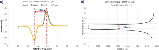
Figure 2. (a) Cyclic voltammetry at 0.05 mV s−1 and (b) Galvanostatic profile of LFP vs Li/Li+ half-cell at 1 C rate with the voltage window 3.2–3.7 V at RT.
Download figure:
Standard image High-resolution imageThe rate tests were conducted at various charge and discharge rate protocols, the half-cells were first charged at 1Cch rate and discharged at 1, 2, 4, 6, 8Cdisch rates; followed by charging and discharging at same current rates such as 1Cch/disch, 2Cch/disch, 4Cch/disch, 6Cch/disch and 8Cch/disch, respectively (Fig. 3). LFP half-cells exhibit discharge capacities of 148, 130, 110, 90 and 74 mAh g−1 at 1, 2, 4, 6, 8Cdisch rates, respectively with the coulombic efficiency of ∼99.99%. The capacity recovery is excellent even when we shuttle the current rates from lower to higher and vice versa (Fig. 3). The low overpotential and high rate capacities (74 mAh g−1 even at 7.5 min (8 C)) of LFP half-cells using IE indicate the higher electrochemical kinetics and lower internal resistance, suggesting a better electrochemical activity of LFP in highest ionic conductivity non-flammable IE compared to OE.26,27,34,46
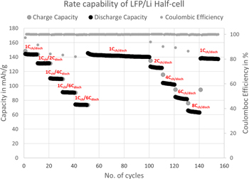
Figure 3. Rate capability of LFP vs Li/Li+ half-cell at the charging rate of 1Cch and then discharged at the rates of 1, 2, 4, 6, & 8Cdisch and followed by charge/discharge at the same rates such as 1Cch/disch, 2Cch/disch, 4Cch/disch, 6Cch/disch & 8Cch/disch with CC test mode and the voltage window 3.2–3.7 V at RT (y-axis shows the specific capacity).
Download figure:
Standard image High-resolution imageFurther, the long term cyclability of the inorganic battery is essential to apprise the commercial viability. The longevity of inorganic battery is evaluated with the full cell configuration of LFP as cathode and graphite as anode active materials with proprietary formulae IE for the first time. The inorganic prismatic cells with 1.08 Ah capacity are used for longevity test with CC-CV test mode and the voltage window 2.5–3.6 V at RT as seen in Figs. 4 and 5. LFP/G prismatic cell shows ultrahigh longevity of 50,000 cycles reaching 20% of residual capacity with the coulombic efficiency of ∼99.99% and constant ohmic resistance at 2 C cycling. The capacity retention is 80, 30 and 20% after 1,800, 30,000 and 50,000 cycles, respectively at RT as shown in Fig. 4. Figure 5 displays the corresponding charge and discharge potential curves of selected cycles such as 10 k, 20 k, 30 k, 40 k, 50 k cycles, respectively. It is encouraging to witness the long cycle life and potential curves behavior of IE LFP/G batteries with the coulombic efficiency of ∼99.99% and constant internal resistance. Apart from higher ionic conductivity of IE, we believe that the stable Solid-Electrolyte Interface (SEI) at the anode during course prolonged cycle life compared to OE LIBs.12,46,49,50 Indeed it is necessary to conduct more research in the direction of understanding the SEI and capacity fading in the inorganic electrolyte system. Furthermore, the poor longevity of organic electrolyte arises mainly from the fact that the cell behavior is not predictable after 80 or 70% of residual capacity and the internal resistance rises unpredictably and thus results in power losses. This is the reason, why traditionally cycle life is limited to relatively high capacities. However, the rising internal resistance is not an issue with the inorganic electrolyte (IE) and thus cycle life is used without limiting to a certain capacity.
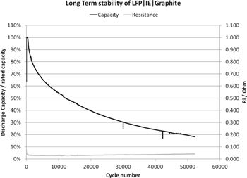
Figure 4. Longevity of LFP/G prismatic cells up to 50,000 cycles with CC-CV test mode and the voltage window 2.5–3.6 V at 2 C rate cycling.
Download figure:
Standard image High-resolution image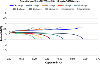
Figure 5. Selected charge-discharge potential curves (10 K, 20 K, 30 K, 40 K & 50 K cycles) of LFP/G prismatic cells with CC-CV test mode and the voltage window 2.5–3.6 V at 2 C rate cycling.
Download figure:
Standard image High-resolution imageMost of the applications require multiple OE-based lithium-ion cells in the battery packs to supply the desired energy and power to technologically advanced machines. However, the possibility of capacity imbalance in the cell packs always exists owing to the capacity variation between the individual cells.51,52 Though the battery pack shows good health with control of battery management system, the lowest capacity individual cells will reduce the safety of the battery pack due to very low tolerance towards over-discharge and overcharge, especially over-discharge of the individual cells.13,42,51 Thus, it is important to develop electrochemical cells with a high over-discharge tolerance and to understand the tolerance of electrochemical cells.13 Arora et al.11 proposed the modelling work that the Cu is oxidized into ions during over-discharge processes and reduced into metallic Cu during the following charge processes. Further, Hao He et al.42 proposed the failure mechanism of 18650 LFP/G battery being over-discharged to 105% and to 120% depth of discharge (DOD). During over-discharge process the Cu is oxidized into Cu+/Cu2+ at the anode side and these cations diffuse into the surface of the electrode. During the charge process, Cu+/Cu2+ ions are reduced to metallic Cu at the surface of the electrodes. These deposits grow into Cu dendrites with the prolonged cycling which causes micro-shorting leading to an increase in cell temperature at the end of over-discharge.53 Herewith, we demonstrate the capability of deep discharge to 0 V of IE LFP/G cells at RT as seen in Figs 6 and 7. Those deep discharged cells show comparable cycling stability of IE cells which are discharged to 2.5 V (Fig. 7), in contrast to OE LIBs which are limited to 100 cycles but only with the over-discharged to 105%.42,53 The IE cells were cycled between the voltage window of 0–3.6 V at 2 C rate and the time interval between charge and discharge was 10 min. After 150 deep discharge cycles to 0 V, no change in the behavior of the cell was observed. No significant changes in capacity and internal resistance were detected (Figs. 6 and 7). This phenomenon may encourage researchers for the development of future energy storage systems which can be capable of tolerating the extreme discharge and charge conditions including the non-flammable electrolyte in the electrochemical cells.
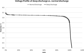
Figure 6. Potential profile of deep discharged cells and normally discharged LFP/G prismatic cells at 2 C rate cycling.
Download figure:
Standard image High-resolution image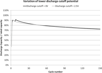
Figure 7. Performance comparison of deep discharged to 0 V LFP/G cells and discharged to 2.5 V LFP/G prismatic cells at 2 C rate cycling.
Download figure:
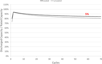
Standard image High-resolution imageHaving seen the promising results of high longevity and depth of discharge capability of IE LFP/G cells, it is also important to improve the capacity retention. For this reason, we have developed an innovative proprietary dip-coating process for LFP electrodes. The cells were assembled with the dip-coated LFP and standard graphite electrodes and results were compared with uncoated LFP and standard graphite electrode cells with proprietary inorganic electrolyte as shown in Fig. 8. The capacity retention is improved by 5% at 1Cch/disch rate using the dip-coating approach on LFP electrodes. The root cause for improvement is not yet fully understood, but it is assumed that attaching an inert stable layer helps to suppress side reactions and thus limits capacity loss.
Figure 8. Lifetime comparison of prismatic LFP/graphite cells with and without dip-coated LFP electrodes at 1 C rate cycling.
Download figure:
Standard image High-resolution image
Conclusions
In summary, we presented the evaluation of longevity and depth of discharge up to 0 V of nonflammable inorganic liquid electrolyte LiFePO4/Graphite (LFP/G) batteries which highly emphasize the alternative inorganic energy storage system for commercial high energy/power applications. This innovative inorganic electrolyte (IE) is prepared by solvating the molten LiAlCl4 salts using liquid/gaseous SO2 (proprietary formulae electrolyte is used) which shows remarkably high Li+ ion conductivity of 121 mS cm−1 at 22 °C. Apart from high conductivity, it exhibits non-flammability which is important for safety of LIBs. IE LFP/Li half-cell exhibits outstanding rate capability up to 8 C at room temperature (RT). For the first time, IE LFP/G prismatic cells show ultrahigh longevity (50,000 cycles at 2 C reaching 20% of residual capacity) with coulombic efficiency of ∼99.99% and lower/constant ohmic resistance at RT. We also demonstrate the deep discharge up to 0 V for 150 cycles at 2 C using IE LFP/G cells which is not feasible with OE LIBs. Further, the stability of cycle life improved by proprietary dip-coating process which shows significant improvement of 5% at RT. Hence, the SO2 solvated molten LiAlCl4 salt electrolyte could serve a good alternative electrolyte for LIBs owing to an impressive longevity, depth of discharge and rate capability of IE LFP/G electrochemical cells. Indeed, it is essential to conduct more research in the direction of inorganic liquid electrolytes.
Acknowledgments
The authors thank all the Innolith supporting team of electrode production, electrolyte production, cell production, filling and testing.