
Abstract
A polypyrrole-intercalated layered manganese oxide nanocomposite  has been synthesized by a delamination∕reassembling process. X-ray diffraction analysis shows that the basal spacing of the
 nanocomposite is
 . The room-temperature conductivity of the
 nanocomposite is found to be
 , which is 4–5 orders of magnitude higher than that of the pristine manganese oxide
 . The improved specific capacitance of the
 nanocomposite
 compared with that of the pristine manganese oxide
 is attributed to a combination of the conductivity effect and the high specific capacitance of PPy.
Electrochemical capacitors (or supercapacitors) are charge-storage devices which possess high power density, excellent reversibility, and long cycle life compared with batteries.1–4 Depending on their charge-storage mechanism, electrochemical capacitors are divided into electric double-layer capacitors (EDLCs) and pseudocapacitors. The energy-storage mechanism of EDLCs relies on the separation of charges at the interface between an electrode and an electrolyte. Various carbonaceous materials ranging from amorphous carbons to carbon nanotubes have been used as electrode materials in EDLCs.2 In the case of pseudocapacitors, a faradaic process occurs in addition to a simple charge separation. Numerous metal oxides and conducting polymers have demonstrated qualifications as electrode materials for pseudocapacitors. Among these materials, hydrated ruthenium oxide exhibits remarkably high specific capacitance, as high as  , and excellent reversibility.5, 6 However, the high cost and the toxicity to the environment have limited its wide application. Therefore, much research interest has focused on other transition metal oxides. In this respect, manganese oxide is one of the most attractive candidates for electrochemical capacitor electrode materials because of its environmental friendliness and low cost.7–9 However, manganese oxide exhibits inferior specific capacitance and electrical conductivity to ruthenium oxide. Polypyrrole (PPy), as a kind of conducting polymer, has advantageous properties with respect to low cost, high conductivity, and high doping∕dedoping rate during charge∕discharge.10–15 However, it exhibits the disadvantage of a low cycle life because swelling and shrinkage may occur during doping∕dedoping processes, thus leading to mechanical degradation of the electrodes and fading of electrochemical performance.16, 17
A combination of manganese oxide and conducting polymer appears interesting for supercapacitor electrodes. The resulting composite is expected to possess synergic properties from both components, such as enhancement in electrical conductivity or electrochemical cycling stability. Recently, Sivakkumar et al. prepared polypyrrole∕hydrous  composite by in situ redox reaction of
 and pyrrole.18 However, the composite with
 particles embedded in a polypyrole matrix showed low electrical conductivity and poor electrochemical properties. It is believed that the nanocomposite with molecular-level hybrid and a relatively ordered polymer chain structure should be useful in improving the properties of electrode materials.19, 20 Therefore, it is of great significance, but it is a challenge to prepare the nanocomposite of layered manganese oxide intercalated with conducting polymer.
In this paper we report on a polypyrrole-intercalated layered manganese oxide nanocomposite  prepared by a delamination∕reassembling process with polypyrrole and
 -octadecyltrimethylammonium-intercalated layered manganese oxide
 in
 -methyl-2-pyrrolidone (NMP) solvent. We study the synthesis mechanism of conducting polymer-intercalated layered manganese oxide and the charge-storage properties of the resulting nanocomposite in aqueous KCl solution. The intercalated nanocomposite shows enhanced electrical conductivity and electrochemical capacitance properties.
Experimental
Preparation and characterization
The  was prepared referring to the method described in the literature.21 A
 sample of
 was put into
 of NMP and sonicated for
 , while
 polypyrrole was added to
 NMP and sonicated for
 . The polypyrrole–NMP colloid was added to the
 suspension and then allowed to stir for
 at
 . The reaction mixture was filtered and washed with acetone and NMP, and then the products were dried at
 for
 . The product was designated as
 . For comparison,
 of
 was added to
 NMP and sonicated for
 , and then centrifuged at
 for
 . The product was washed with acetone several times and dried at
 for
 . The product was designated
 .
X-ray diffraction (XRD) data were collected from a Shimadzu XRD-6000 powder diffractometer using Cu  radiation (
 and
 ) between 3 and 40° with a scanning rate of
 . Electrical conductivity was measured on compacted pellets by a four-probe conductivity method using a four-point probe instrument (Suzhou Telecommunications Instrument Factory, model SX1934). Before measurement, the obtained samples were pressed into cylindrical pellets (
 diam and
 high). The field-emission scanning electron microscope (FESEM) images were taken from a Hitachi S4700 scanning electron microscope.
Electrochemical measurements
The working electrode was prepared by mixing  active material,
 acetylene black, and
 poly(vinylidene fluoride) in NMP and the slurry was spread onto a nickel sheet with
 geometry area. The electrode was heated at
 for
 to evaporate solvent. The total mass of electrode material was about
 . The electrode performance was measured in a beaker-type electrochemical cell equipped with the working electrode, a platinum sheet as the counter electrode, and a standard calomel electrode (SCE) as the reference electrode. The electrolyte was
 KCl aqueous solution. Cyclic voltammetry (CV) scans were recorded from
 (vs SCE) using a Zahner IM6e electrochemical workstation. Electrochemical impedance spectroscopy (EIS) analyses were conducted using an IM6e over a frequency range of
 at an ac amplitude of
 . The galvanostatic charge–discharge cycling properties were evaluated with an Arbin
 galvanostat∕potentiostat.
Results and Discussion
The  has a layered structure with a basal spacing of
 (Fig. 1a). When the
 and NMP mixed solution was treated by ultrasonics, a colloid suspension of manganese oxide was obtained. The delaminated
 slurry was collected by centrifugation and subjected to XRD analysis in the wet state. The wet-state XRD pattern (Fig. 1b) shows no clear peaks but only an amorphous halo in contrast to that of
 . The absence of
 reflections indicates that loss of the original crystalline structure and the layered manganese oxides are delaminated to the individual primary layers.22 The delaminated
 slurry was dried, and a layered structure with a basal spacing of
 reappeared
 , as shown in Fig. 1c. When polypyrrole was treated with delaminated
 suspension in NMP solvent, a new layered structure with a basal spacing of
 was obtained (Fig. 1d), which suggests that polypyrrole-intercalated layered manganese oxide nanocomposite is successfully prepared by a delamination∕reassembling process. The room-temperature electrical conductivities of
 and
 samples are
 and
 , respectively. The electrical conductivity of
 nanocomposite is 4–5 orders of magnitude higher than that of
 , which indicates that intercalation of polypyrrole into layered manganese oxide can greatly improve the electrical conductivity of manganese oxide.
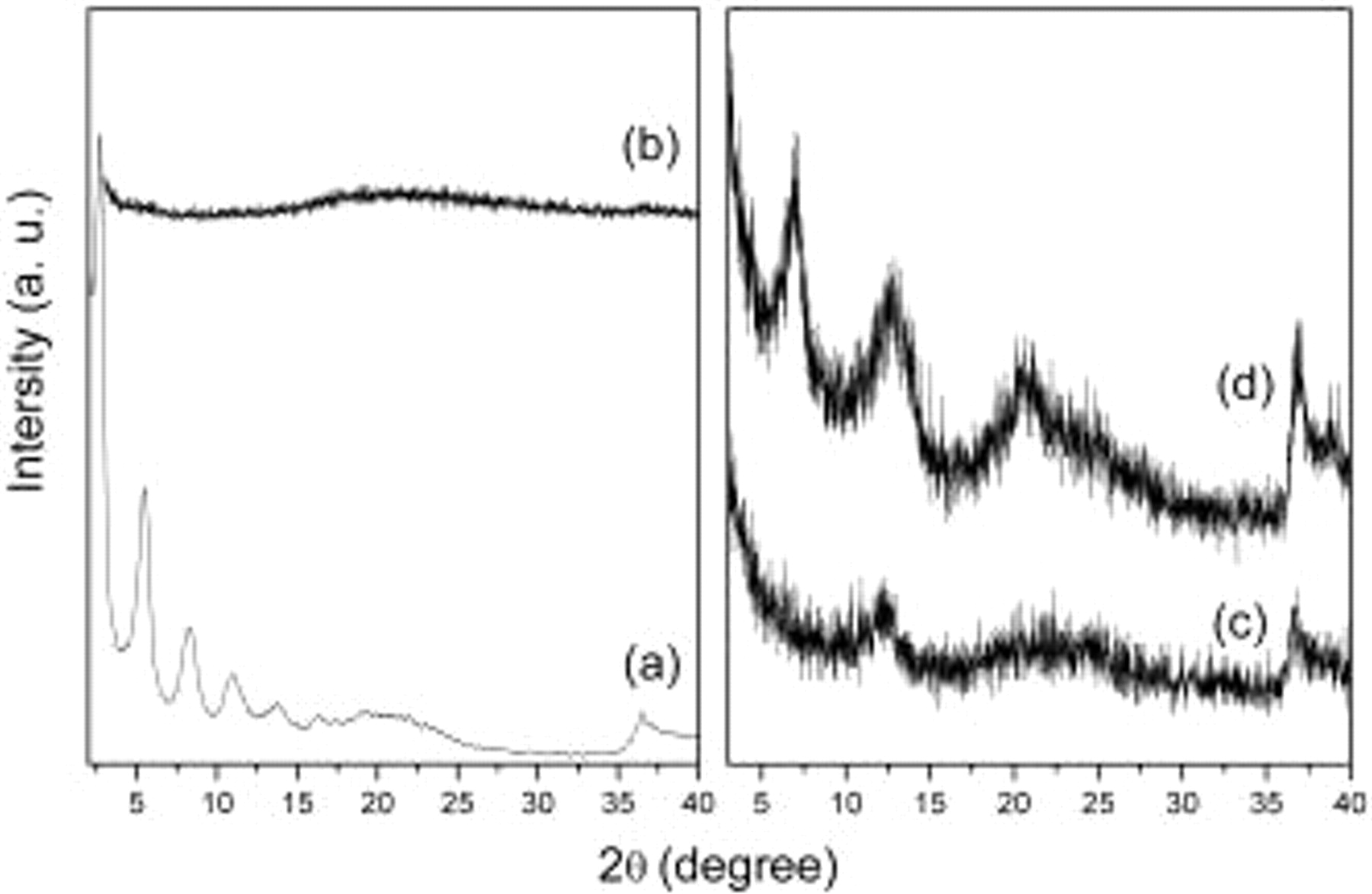
Figure 1. XRD patterns of (a)  , (b) delaminated
 slurry (wet state), (c)
 , and (d)
 .
Figure 2 shows FESEM images of  and
 , respectively. It is apparent that
 and
 products are comprised of platelike particles, which are
 in lateral dimensions and about
 in thickness. The electrode materials in nano-size should give the opportunity of obtaining enhanced capacitance due to surface effects.
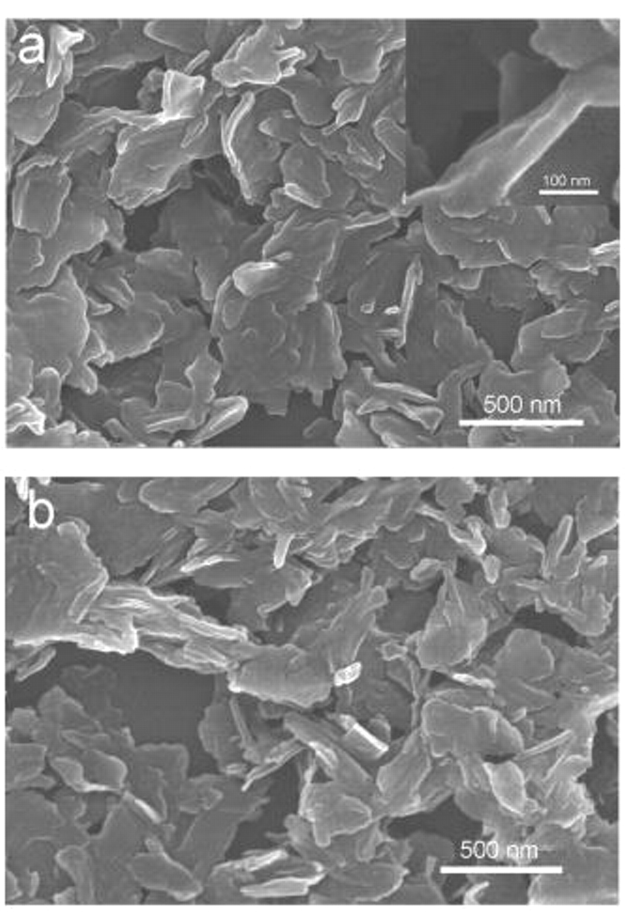
Figure 2. FESEM images of (a)  and (b)
 .
CV and galvanostatic charge∕discharge tests were employed to characterize the electrochemical capacitance performance of  nanocomposite. Figure 3a shows the cyclic voltammograms of PPy,
 , and
 electrodes with a sweep rate of
 in a potential range between 0 and
 (vs SCE). The CV curves of
 and
 electrodes show roughly rectangular mirror images with respect to the zero-current line, indicating the capacitive behaviors. However, the pure PPy electrode has poor capacitive behavior in the potential range between 0 and
 (vs SCE). The potential window is an important effect on the capacitive behavior of PPy. In a previous report, Hu and Lin indicated that a good electrochemical reversibility of PPy in the potential region of
 and
 (vs
 ) was obtained.13 Generally, manganese oxide electrodes exhibit highly electrochemical reversibility between 0 and
 (vs SCE or
 ) in neutral electrolyte.7 In our experiments, we thus chose the potential range between 0 and
 in order to fit the capacitive behaviors of manganese oxide electrodes.
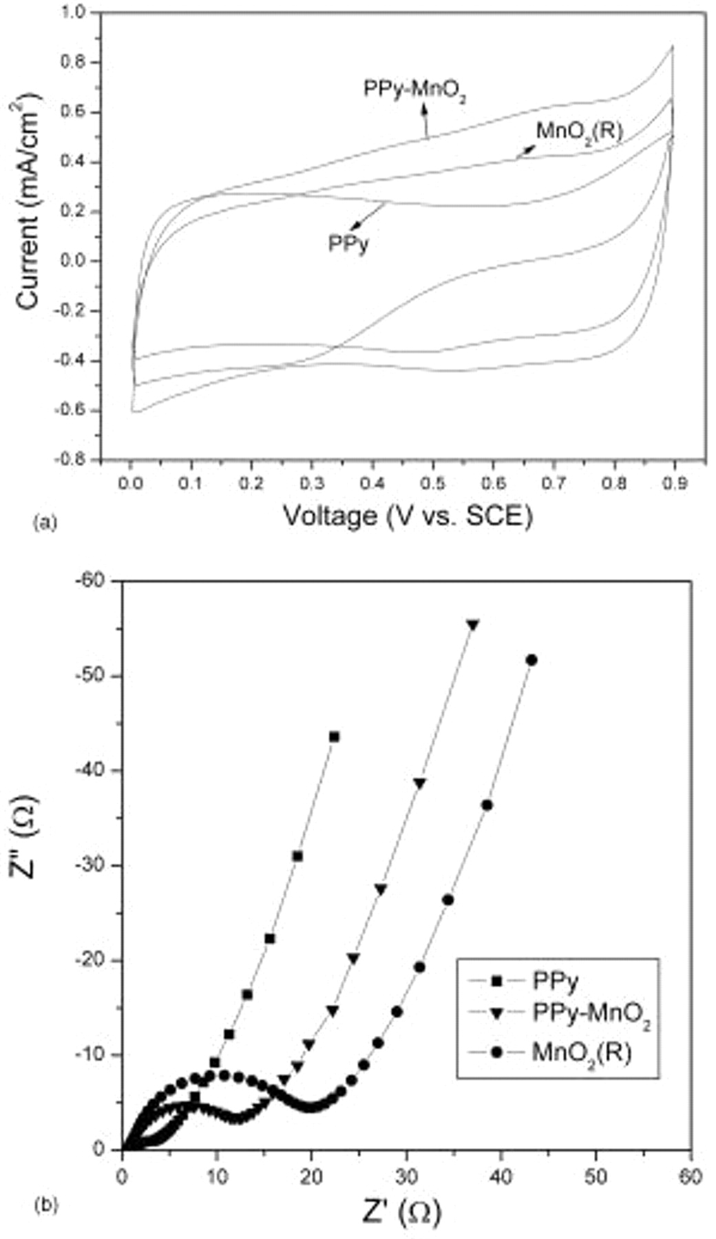
Figure 3. (a) CV images of PPy,  , and
 electrodes. Electrodes are scanned in a potential range of
 (vs SCE), and the scan rate is
 . (b) EIS plots of PPy,
 , and
 electrodes.
Figure 3b shows EIS plots of PPy,  , and
 electrodes at open-circuit potential. The impedances of the above three electrodes consist of a depressed arc in the high-frequency regions and a straight line in the low-frequency regions. Generally, the semicircle reflects the charge-transfer process at the electrode∕electrolyte interface, and the straight line represents the diffusion of electroactive species.23–27 The lowest impedance at the low-frequency end for the PPy electrode among the three spectra indicates that the PPy electrode can provide higher pseudocapacitance than that of
 and
 electrodes.
 electrode shows a lower charge-transfer resistance and diffusion impedance than those of
 electrode. The result suggests that a better kinetics of
 electrode can be obtained by intercalating polypyrrole into manganese oxide, which may be ascribed to the enhanced conductivity and capacitance of
 nanocomposite.
Figure 4a shows the charge∕discharge curves of  and
 electrodes at current densities of 0.2 and
 (based on the total mass of electrode material) or 0.1 and
 , respectively. All the charge curves are very symmetric to their corresponding discharge counterparts in the whole potential region, and the slope of every curve is potential-independent. The obtained charge∕discharge curves are used for the calculation of specific capacitance (SC) from the equation

where  is the slope of the linear discharge curve,
 is the current, and
 is the mass of active material within the electrode material. The SC value of
 at current densities of 0.2 and
 are 290 and
 , respectively. The capacitance retention is about 79%. In the same process, the SC value of
 decreases from
 (at a current density of
 ) to
 (at a current density of
 ). The capacitance retention is about 72%. The
 nanocomposite shows higher capacitance and rate capability than that of
 , which is due to the combination of the conductivity effect and the high specific capacitance of PPy.28
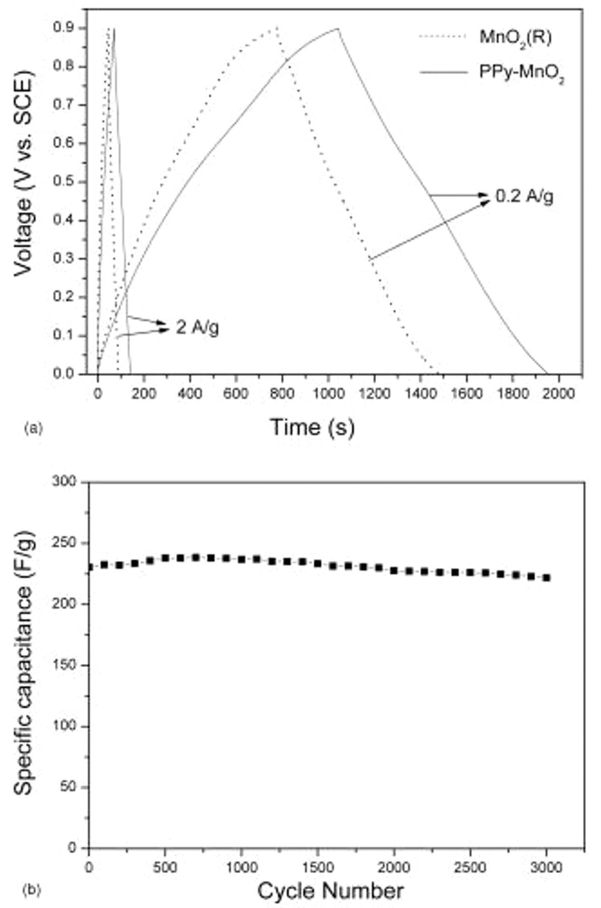
Figure 4. (a) Charge∕discharge curves of  and
 electrodes in the potential range of
 (vs SCE) at different current densities. (b) Cyclic performance of
 electrode at a current density of
 .
The values of specific power (SP) and specific energy (SE) are calculated using the following equations


where  is discharge time, and
 is the potential window of charge–discharge cycling. The SE values of
 electrode are in the range of
 , while the SP values are in the range of
 , revealing that there is a decrease in SE of the electrode material with an increase of SP. The SE values of
 electrode are in the range of
 , while the SP values are in the range of
 . Thus, the
 electrode shows a better specific energy than that of
 electrode.
After  of charge∕discharge tests at a current density of
 , the
 electrode can maintain
 of its initial capacitance (Fig. 4b). This result indicates that the
 nanocomposite has a good long-term electrochemical stability at a relatively high current density.
Conclusions
A polypyrrole-intercalated layered manganese oxide nanocomposite is synthesized through a delamination∕reassembling process between  -octadecyltrimethylammonium-intercalated precursors and polypyrrole in an organic solution. The
 nanocomposite shows good electrochemical properties in
 KCl solution. The SC for
 nanocomposite is about
 at a charge∕discharge current density of
 . The SC of
 nanocomposite can maintain 96% of initial SC after
 at a current density of
 . The intercalation of polypyrrole into layered manganese oxide can improve the electrical conductivity and electrochemical capacitance properties of nanocomposite, which is due to the synergic effects from each pristine component.
Acknowledgments
This research was supported by the National Natural Science Foundation of China, the Ministry of Science and Technology High Technology Development 863 Plan (grant no. 2006AA03Z343), and the 111 Project (grant no. B07004).
Beijing University of Chemical Technology assisted in meeting the publication costs of this article.