
Abstract
Many engineering applications require components with a good surface finish. It is difficult to get the surface finish in the micro/nano level range with conventional finishing processes for materials such as super alloys, composites, and ceramics. Magnetic abrasive finishing (MAF) is one of the processes for achieving superior surface finish. However, the processes efficiency is affected by its operational variables. Even a slight change in a processing parameter may lead to dimensional inaccuracies and poor surface quality of the workpiece. In this paper, recent trends in the magnetic abrasive finishing process are presented along with a critical review. The review includes MAF principles, tools, hybridization, modeling, and simulation of the process. Apart from plane MAF, the principle of MAF for cylindrical workpieces, the mechanism of material removal and the effect of different types of abrasives are also discussed. Various machine tools used for MAF of plane and cylindrical workpieces for external and internal surfaces are also discussed. In hybridization, different processes combined with MAF, like ultrasonic-assisted MAF, chemo-assisted MAF, and electrochemical-assisted MAF, etc, are discussed to increase material removal rate and obtain surface finish at the micro/nano level. The paper also covers mathematical and statistical modeling, simulation, and optimization techniques to predict and optimize the set of input process parameters. Lastly, challenges and conclusions of the MAF process are presented.
Export citation and abstract BibTeX RIS
1. Introduction
Finishing the high-strength materials and super alloys necessitates the development of un-conventional finishing processes. Finishing these materials with traditional finishing methods such as grinding, lapping, and honing is a challenging task due to their high hardness and intricate profile, which leads to low efficiency in preparing the surfaces of components [1–5]. The surface roughness of the components is a critical characteristic that affects corrosion resistance, fatigue, and tribological properties [6–9]. Further, it also contributes to the aesthetic appearance of the engineering parts. The high degree of surface finish and close dimensional tolerance are major requirements for aviation, automobile, and medical industries [10, 11]. However, the cost associated with higher surface finish and close dimensional tolerance increases exponentially. The finishing process, although the final step in manufacturing, accounts for approximately 12%–15% of the total manufacturing cost [12]. A substantial portion is dedicated to labor costs, material costs, finishing tools, skilled technicians, operators, tolerances, and quality control personnel essential for the meticulous execution of finishing tasks [13]. Conventional finishing methods and non-conventional machining processes tend to leave residues on the workpiece surface. These residues can appear as burrs, surface cracks, thermal stresses, heat-affected zones, or undesired recast layers formed during non-conventional machining processes like electro-discharge machining (EDM) and electrochemical machining (ECM) [1, 14–16]. A Difficult-to-machine material like Inconel 625 poses significant challenges for processes like powder-mixed EDM and wire EDM. These processes leave residue on the machined surface, which results into defect such as uneven surface roughness, surface micro-cracks, and voids, hindering its performance and reliability [17–19]. Burrs are the unwanted raised edges or rough protrusions that result from the cutting or machining process. It may affect the aesthetics, dimensional accuracy, corrosion resistance, and fatigue resistance in cyclic loading, and sharp edges pose safety risks during handling [20–22].
Similarly, recast layer formation can alter material properties and compromise surface integrity, impacting fatigue performance, corrosion resistance, and dimensional accuracy. Managing the recast layer is crucial to maintain the components strength, durability, and overall integrity, requiring careful machining parameters and post-processing treatments [23–26]. Thermal stresses and heat-affected zones (HAZ) can significantly affect the performance and integrity of machined components. These factors lead to altered mechanical and microstructure changes and increased susceptibility to cracks, affecting fatigue resistance and overall structural integrity [27, 28]. Therefore, achieving nano-level surface finishes necessitates the development of alternative finishing and polishing techniques used by various industries, such as advanced finishing technologies, and electrolytic in-process dressing (ELID) technology [29–31].
Surface with roughness at the micro or nano level can be produced using techniques like abrasive flow machining (AFM) or sandpaper finishing, which uses fine abrasive particles [32]. However, these techniques require a lot of labor and have low productivity, and lack of process control issues is frequently encountered. Table 1 lists the value of surface roughness obtained by different conventional and advanced finishing processes [33, 34]. The data reveals that material removal processes at the atomic or molecular level can yield surface finishes below 1 nanometer through an advanced finishing process. In addition to this, the conventional finishing techniques are not suitable for the parts with generative design, which are mainly produced by additive manufacturing [35]. These free-form shapes with generative designs, which are gaining popularity for weight reduction and functional properties, can be finished through magnetic field-assisted abrasive finishing (MFAF) with a suitable shape of magnetic tool [36].
Table 1. Range of surface roughness obtained by various finishing process [33, 34].
| S. No. | Finishing process | Approximate Ra value (nm) |
|---|---|---|
| 1. | Grinding | 0.1–1.6 |
| 2. | Honing | 0.1–0.8 |
| 3. | Electro-polishing | 0.8 |
| 3. | Lapping | 0.05–0.4 |
| 4. | AFM with SiC abrasives | 50 |
| 5. | MAF | 8.0 |
| 6. | Magnetic float polishing (MFP) with CeO2 | 4.0 |
| 7. | Magnetorheological finishing (MRF) with CeO2 | 0.8 |
| 8. | Elastic emission machining (EEM) with ZrO2 | <0.5 |
| 9. | Ion beam machining (IBM) | 0.1 |
The MAF process was introduced in the 1930s in the United States, whereas practical usage started in the 1980s and 1990s to overcome the above challenges of conventional finishing processes [37]. It is an alternative for finishing difficult-to-machine materials and intricate profiles over other traditional finishing processes [38, 39]. MAF holds significant promise as a surface finishing technique, capable of attaining surface finishes at the micro/nano level with minimal residual impact on the finished surface [40]. MAF can be used on materials, which are magnetic as well as non-magnetic. Apart from flat surfaces, MAF process can also be applied to finish cylindrical workpieces such as external and internal surfaces, i.e. flat disks, internal surfaces of pipes, cylindrical rods, bent tubes made of steel, superalloys, and ceramic [41, 42]. In the MAF process, a brush made up of ferromagnetic and abrasive particles, which are flexible, is formed. MAF became popular due to the better controllability of the process, the tools flexibility, and self-sharpening behavior [43, 44]. The MAF process can be implemented through different traditional machine tools such as lathes, milling and drilling machines, etc [44–46]. The rise in temperature between the tool and workpiece during MAF can be regulated by the proper selection of parameters such as tool speed, magnetic flux density and, working gap etc Kumar and Yadav investigated the rise in temperature through finite element method (FEM) and found that rotational speed and magnetic field intensity were most influential parameters [47]. Ihara and Nakano [48] investigated MAF on diary sector stainless steel tubes and improved surface roughness up to 0.037 μm, reducing milk accumulation on inside surface tubes. Further, Singh et al [49] examined an experimental investigation of temperature generation in MAF on Aluminum 6060 and developed a model through Buckingham  -theorem for forecasting temperature for various materials. Many techniques have been used to determine the temperature of the surface, such as embedded thermocouples, an infrared temperature detector, and a radiation pyrometer. Fan et al [50] developed a novel MAF tool for finishing titanium alloy. They investigated the effect of working gap, abrasive particle size, rotational speed, and feed rates on surface finish, and it was found that there was an improvement in surface finish from 1.121 μm to 46 nm. Nagdeve et al [51] designed and developed a novel finishing tool for MAF and fitted it to a lathe machine. This tool provides longitudinal motion along an axis and achieves surface roughness up to 96 nm. Li et al [52] investigated the hybrid post-processing techniques of MAF and post-heat treatment (HT) for additively manufactured Inconel 718 superalloys. They reported improved mechanical properties of yield strength of 1147 MPa, an ultimate tensile strength of 1334 MPa, and an elongation of 22.9%. Deng et al [42] used MAF to finish the inner surface of ultra-fine Ni-Ti alloy tubes utilized for cardiovascular stent manufacturing. They reported effective removal of surface defects and significant improvement in surface roughness from 0.75 to 0.08 μm.
This paper presents the state-of-the-art and recent trends of the MAF process. The organization of this paper is as follows: the principles of MAF, along with the mechanism, types of abrasive particles and machine tools used in the literature, are discussed in section 2. Section 3 discusses the hybridization of MAF with the assistance of various non-conventional finishing processes, such as ultrasonic, chemical, and electrochemical processes. In section 4, modeling and simulation of the process are discussed. Challenges and conclusions of the MAF process are presented in sections 5 and 6, respectively.
2. Principle of magnetic abrasive finishing (MAF)process
In the MAF process, the relative motion between the workpiece and tool is obtained by rotating either the magnet or workpiece. The workpiece acts as a south pole in case of magnetic materials. In case of MAF for cylindrical workpieces, magnetic abrasive particles (MAPs) are placed between the rotating workpiece and the poles of the magnet, as shown in figure 1(a). The prepared MAP mixture aligns them along the magnetic field line and forms a flexible magnetic abrasive brush (FMAB) [53–56]. During the continuous rotation, surface finishing occurs as a result of relative motion between FMAB and the workpiece [45]. Two types of forces act on the workpiece, one is normal, and the other is tangential force during finishing. Normal force influences the depth of indentation, while the tangential force is responsible for the shearing action of the workpiece [57–60]. Material removal from the workpiece takes place due to this shearing action. With micro-size MAPs, an excellent surface finish can be obtained in the range of μm or nm; however, the material removal rate (MRR) is less [61, 62].
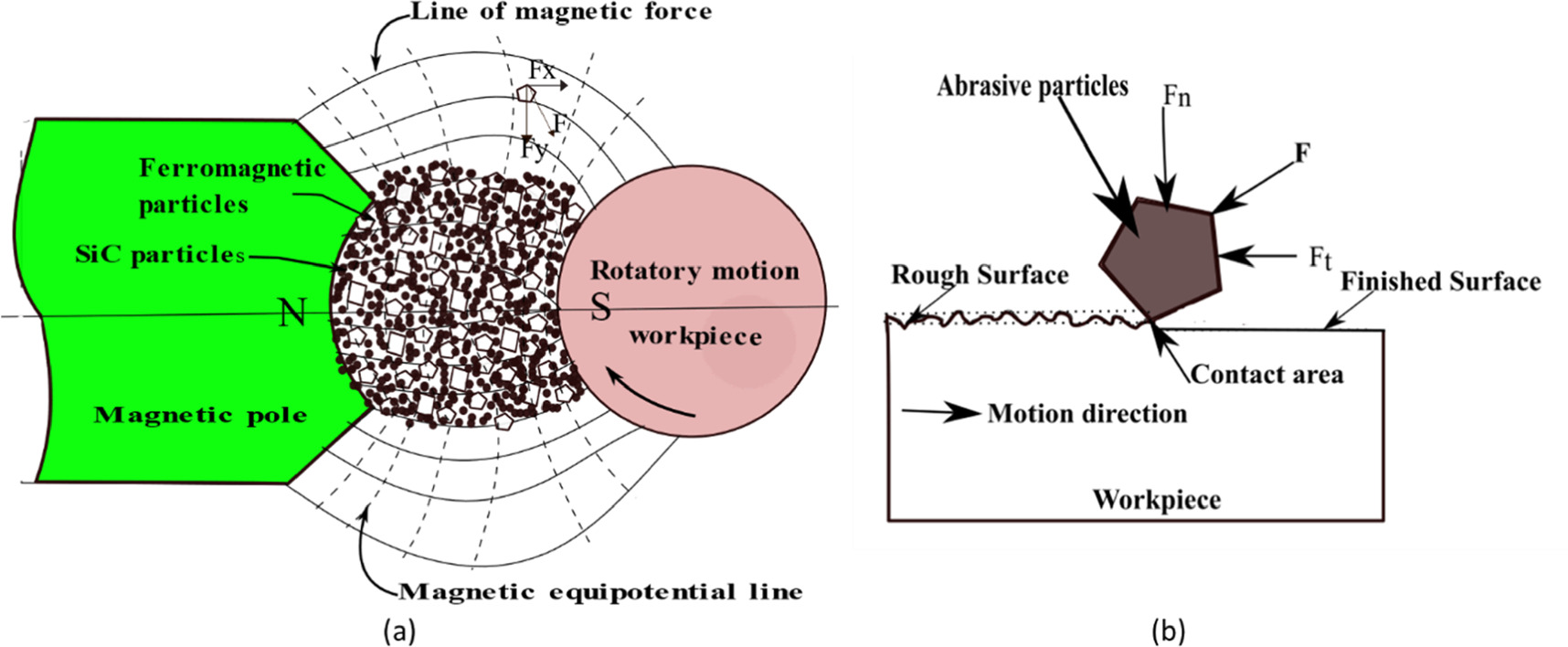
Figure 1. (a) Schematic diagram of MAF process for cylindrical workpiece (b) Forces acting in MAF process.
Download figure:
Standard image High-resolution imageMAF process has several process parameters. In addition, several system-dependent parameters make the entire process complex. Even a slight disturbance in the processing parameter may lead to inaccuracies and poor surface quality. Parameters that influence the output process parameters are shown in figure 2. The mechanism of material removal and cutting forces are also greatly influenced by small changes in process parameters are presented in sub-section 2.1.

Figure 2. Fishbone diagram of various parameters of MAF.
Download figure:
Standard image High-resolution image2.1. Mechanism of material removal in MAF
Figure 1(b) shows two forces acting on the MAPs during finishing, namely normal force (Fn) and tangential force (Ft) on the workpiece. The indentation is caused by normal force and keeping all ferromagnetic particles together, whereas tangential force (Ft) is responsible for shearing off-chip at micro-level due to relative motion between the FMAB and workpiece. Both forces are responsible for removing the asperities in the micron size from the surface until the desired level of surface finish is achieved. Figure 1(a) illustrates the schematic representation of the magnetic field distribution between the north and south poles. The magnetic field gradient at position 'A' exerts a force on a ferromagnetic particle has two components,  and
and  namely, horizontal and vertical components.
  and
and  can be obtained from equations (1) and (2) [63].


Where x is the magnetic force direction, and y is the magnetic equipotential line direction,  is the ferromagnetic particle susceptibility,
  denotes permeability of the vacuum, V denotes volume of ferromagnetic particles, H denotes the magnetic field strength at A,
  and
and  are magnetic field gradients in respective
  and y-directions.
Further forces  and
and  at each particle resolved into the normal and tangential direction in two-dimensional plain (X-Y plane). The normal force is applied perpendicular to the workpiece, pressing the MAPs against the workpiece surface and responsible for depth of penetration. Higher normal force can result in a more aggressive material removal rate, but excessive force may lead to surface damage or increased surface roughness. Therefore, a balanced normal force is crucial to achieve the desired MRR while maintaining surface roughness. However, the tangential force in MAF is responsible for moving the MAPs along the workpiece surface. It influences the cutting action of the abrasive particles and, consequently, the MRR. Controlling the tangential force is crucial for preventing surface defects such as scratches or uneven finishes. Proper tangential force adjustment helps to achieve a uniform and controlled abrasion action, leading to a smoother surface finish. The normal force on the workpiece was calculated using equation (3) [64].

Where  is the depth of indentation,
  is workpiece hardness,
  is semi-included, angle,
  is the number of abrasive particles participating in finishing.
The normal force is influenced by the magnetic field gradient, while the tangential force is determined by the strength of the magnetic field produced by either a permanent magnet or an electromagnet. The MAPs orient themselves in a parallel manner to the direction of the magnetic field lines due to the dipole lines of force produced by a magnet [65]. Voltage and current of an electromagnet are responsible for the stiffness of FMAB [66, 67]. An electromagnet can have a direct current (DC) or alternating (AC) power supply. An electromagnet with an AC power supply can generate an alternating magnetic field. Alternating magnetic fields can re-arrange abrasive particles in every new cycle, due to which fresh abrasive particles participate in material removal. Due to this reason, good surface finish can be obtained compared to a permanent magnetic field [62, 68, 69]. However, the loss of magnetic field strength varies in a cycle, so an electromagnet with a DC power supply is preferable.
Researchers have consistently reported dynamic trends in MRR and surface roughness during finishing processes. In the initial stage of the process, MRR is more and subsequently starts decreasing towards the end of the finishing [70]. The phenomenon is interlinked with the evolving surface roughness and irregularities on the workpiece surface. As the surface undergoes finishing, the apparent contact area increases, leading to a decreasing shearing effect on irregularities and a transition to a steady-state removal process [71].
2.2. Magnetic abrasive particles
MAPs are the combination of ferromagnetic and abrasive particles (SiC, Al2O3, Cubic boron nitride), which play a crucial role in the surface finishing procedure. The proportion of ferromagnetic and abrasive particles creates suitable pressure and force by FMAB on the workpiece. Ratio of ferromagnetic and abrasive particles used for preparation of MAPs is usually in the range of 60:40 to 80:20 [72]. In MAF, MAPs are used in two forms: (i) unbonded MAPs and (ii) bonded MAPs as shown in figures 3(a) and (b) respectively. Unbonded MAPs are homogeneous mixtures of ferromagnetic and abrasive particles with lubricant. Bonded MAPs are made by either gas atomization, sintering or rapid solidification of mixture of ferromagnetic and abrasive particles to form a matrix [73–77].
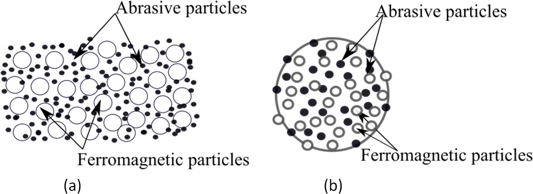
Figure 3. Representation of MAPs (a) Unbonded MAPs (b) Bonded MAPs.
Download figure:
Standard image High-resolution imageIn the case of unbonded MAPs, whenever the magnetic field is applied, carbonyl iron particles (CIP) form chains between the poles of the magnet [78, 79]. In this case, abrasive particles can move freely inside the magnetic field region. However, in case of bonded MAPs, abrasive particles are restrained from free movement. The selection of ferromagnetic and abrasive particles employed in the process depends upon the characteristics of the material of the workpiece that needs to be finished. It is necessary to select appropriate MAPs based on the requirement of surface roughness. When unbonded MAPs are used in the process, some abrasive particles are embedded in the finished surface of the workpiece. Such phenomena are absent in the case of bonded MAPs [77].
Depending upon the material mechanical and physical properties, various researchers has investigated different types of abrasive particles, including silicon carbide (SiC) [80, 81], chromium oxide (Cr2O3) [47], diamond paste [82], aluminum oxide (Al2O3) [83–86], Boron carbide [87] and cubic boron nitride (CBN) [88] in different forms.
2.3. Machine tools used for MAF process
According to the profile to be finished, different machine tools may be needed to operate a MAF attachment setup, such as a lathe, vertical milling machine, drilling machine etc The workpiece processed with the MAF process can be of two categories: finishing of external surfaces, such as cylindrical or planar surface and finishing of internal surfaces of the cylindrical workpiece (capillary tube, cardiovascular stent tubes etc). The list of different machine tools, abrasives, and materials used in MAF by different researchers is listed in table 2.
Table 2. List of different machines, abrasives, magnets, and materials for MAF.
| S. No. | Type of machine tool | Abrasive | Type of magnet | Workpiece material | Main observations | Article references |
|---|---|---|---|---|---|---|
| 1. | Lathe | Al2O3 | Electromagnet with DC power supply | Aluminum | Ra decreased from 0.46 μm to 0.18 μm | [44] |
| 2. | CNC milling | SiC | Electromagnet with DC power supply | SS304 steel | Ra improved by 70.1% | [89] |
| 3. | Independent machining setup | SiC | Electromagnet with DC power supply | SKD11tool steel | polyhedron shape gives the best Ra of 0.042 μm | [90] |
| 4. | Pneumatic vibrator-based setup | G50 steel grit abrasive particles | Nd-Fe-B permanent magnet | SLM manufactured SS316L | 75.7% improvement in surface roughness Ra was achieved | [91] |
| 5. | Vertical milling machine | Al2O3 | Nd-Fe-B permanent magnet | Cu-alloy | Overall surface finish improved up to 79.52% | [46] |
| 6. | CNC milling machine | Alumina (Al2O3) | Nd-Fe-B permanent magnet | Silicon wafer | Improvement in Ra was up to 89% with 24.5 nm surface roughness | [92] |
| 7. | Lathe | Bonded MAPs of Al2O3 and iron powder (40/60) | Electromagnet with DC power supply | SS302 steel | ANN-GA result was 7% better than Taguchi-ANOVA | [53] |
| 8. | Vertical milling machine | Bonded Diamond, CBN, Alumina MAPs | Nd-Fe-B permanent magnet | Plane SS304 steel | Diamond MAP produced better surface finish than CBN and Alumina | [93] |
| 9. | Vertical milling machine | Al2O3 abrasive and Iron powder | Nd–Fe–B permanent magnets | BK7 optical glass | Obtained Ra was up to 23 nm | [94] |
| 10. | Vertical milling machine | SiC and Al2O3 | Nd–Fe–B permanent magnets | AISI 1018 steel | Abrasive type and speed are critical parameters | [95] |
| 11. | Independent machining setup | Diamond Powder | Electromagnet AC power supply | Alumina ceramic plate | surface roughness value reduced to 106.3 nm from 244.6 nm | [69] |
| 12. | Desktop drilling machine | Diamond Powder | Nd–Fe–B permanent magnets | Alumina ceramic plate | Surface roughness value reduced to 3.67 nm from 202.11 nm | [96] |
2.3.1. Plane MAF setups used in literature
Plane surface workpieces [97, 98] with free-form or complex surfaces use planar tool attachment because FMAB can adjust the shape according to the profile of workpiece surfaces (e.g. free form surface, complex curve surface and plane surface). These MAF attachments are mainly attached to either a vertical milling machine [99, 100] or a lathe machine with a specially designed fixture. Barman and Das [101] designed and developed a MAF setup for a plane workpiece by utilizing permanent magnet to produce a magnetic field between the workpiece and tool, as shown in figure 4. The FMAB formed by a permanent magnet could not press the tool on the workpiece surface because magnetic field lines generated by the permanent magnet form a complete circuit only around itself. A permanent magnet improved the surface finish, but the finishing efficiency of MAF was poor due to the field line not penetrating the workpiece [102]. In order to increase the stiffness of FMAB and finishing efficiency of the MAF process, Kwak placed a magnet on both sides of the workpiece to confine the magnetic flux density and found that there were further improvements in surface roughness than single side permanent magnet due to an increase in stiffness of FMAB [103]. Pandey et al [92] proposed a chemo-assisted double-disk magnetic abrasive finishing on a silicon wafer for further improvement in response variables and reported improvement in surface finish and MRR. Further research shifts from permanent magnet to the electromagnet to study the forming behaviors of FMAB. Magnetic field intensity can be adjusted for an electromagnet by changing the supply voltage and current. Singh et al [49] used an electromagnet for forming the FMAB through DC power supply. The impact of different variables, including working gap, abrasive weight, voltage, and rotational speed, was analyzed, and it was found that voltage is the most significant factor for temperature rise and surface finish improvement.
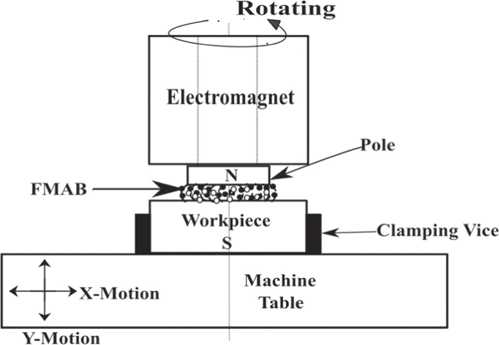
Figure 4. Schematic diagram of MAF process for plane surface.
Download figure:
Standard image High-resolution image2.3.2. Cylindrical (external and internal surface) MAF setups used in literature
Figure 5(a) illustrates the schematic diagram of the cylindrical MAF process configuration, where a cylindrical workpiece is placed between the magnetic poles [104–106]. Here, tools are mostly stationary and provide rotational motion to the workpiece. Both types of abrasive, either bounded or unbounded, can be used. When the workpiece begins to rotate, prepared MAPs form FMAB when exposed to a magnetic field, and finishing occurs due to the workpiece movement relative to the FMAB. Jain et al [43] investigated surface finish and MRR on the outer surface of cylindrical workpieces with respect to the circumferential speed and working gap. For further improvement, the researcher provided either vibration to the workpiece or combined the MAF process with the non-conventional machining process [44, 107]. The MAF process can also finish the cylindrical internal surface of workpiece by rotating the workpiece or magnet. Yamaguchi & Shinmura were the first to propose finishing an internal pipe surface using the MAF process. Figure 5(b) illustrates the internal cylindrical MAF process. The magnetic jig consists of two magnets that are integrated by a yoke. It is arranged in an N-S-N-S like pattern to make a compact magnetic circuit in the pipe. Because of the rotation of the workpiece, a relative motion occurs between the MAPs inside the workpiece. Finishing takes place around the interior surface of a cylindrical workpiece. Accordingly, we get a smoothed inner surface. Singh & Singh [108] employed a DC power supply and two electromagnetic poles that are oriented perpendicularly to each other to generate a magnetic field. They found that the percentage improvement in surface finish was approx 94% with a surface roughness value of 0.04 μm. Verma et al [109] designed and developed a setup utilizing a permanent magnet for finishing the internal surfaces of pipes, grooves, and vertical surfaces. In their investigation, they focused on the SS304 steel pipe and found that magnetic flux density was the most influential parameter, and they were able to achieve up to 56 nm surface finish at optimum process parameters. Kajal et al [110] performed MAF on the internal surface of a gun barrel and achieved the surface finish up to 150 nm. This reduced friction and heat generation between the bullet and gun barrel. Deng et al [42] used MAF to remove surface defects such as cracks and scratches from the internal surface of Ni-Ti alloy tube, which is utilized in the implementation of cardiovascular stent tubes.

Figure 5. Schematic diagram of MAF process for cylindrical (a) External surface (b) Internal surface [109, 110].
Download figure:
Standard image High-resolution image3. Hybridization of MAF
Materials on which MAF process was used can be broadly categorized into magnetic and non-magnetic materials. On magnetic materials, better surface finish and MRR are achieved compared to non-magnetic materials due to more stiffness of FMAB in the former case. Moreover, physical and mechanical characteristics of the material also influence improvement in surface roughness and MRR, such as hardness, toughness etc Some of the materials on which the MAF process was performed were as follows: silicon wafers [92], aluminum alloys [111], stainless steels [105, 112], BK7 Optical glass [94], β-TNTZ alloy [113], Ti-6A-4V alloy [72], ceramics [69], Inconel 718 [114]. However, advanced materials are being developed over time, and further investigation is required to improve the MAF process efficiency (especially in non-magnetic material).
To enhance the efficiency of MAF, some researchers used hybridized MAF processes such as ultrasonic-assisted MAF, chemo-assisted MAF, and electrochemical-assisted MAF. Some of the benefits of hybridized MAF over traditional MAF are shown in figure 6. Details of these hybrid processes are briefly presented in the following sub-sections.
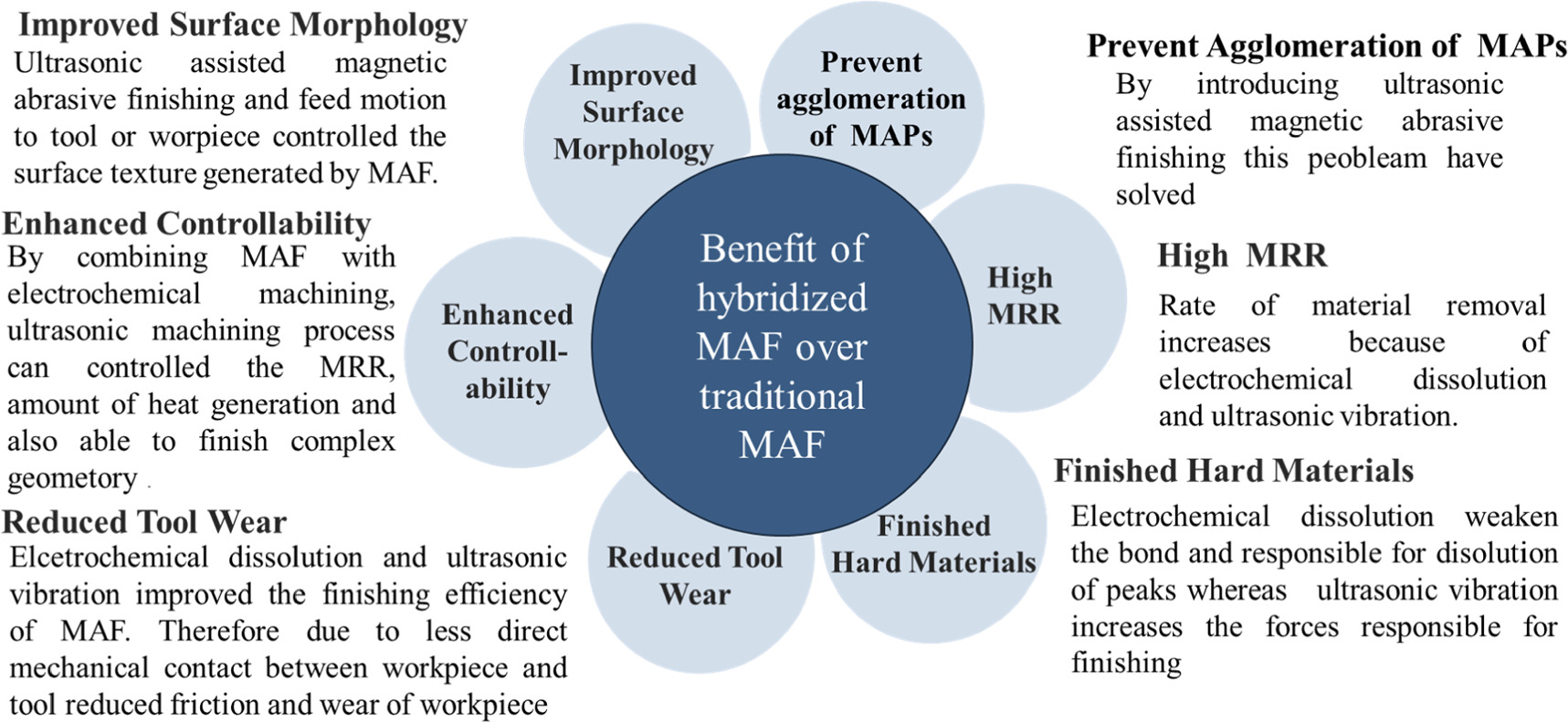
Figure 6. Finishing characteristic improved by hybridization of MAF.
Download figure:
Standard image High-resolution image3.1. Ultrasonic-assisted magnetic abrasive finishing (UAMAF)
Researchers conducted various studies by combining MAF using vibration-assisted/ ultrasonic-assisted processes, as shown in figure 7. Vibration was given to the workpiece or tool in horizontal or vertical direction. In the UAMAF process, surface finish is achieved due to the relative motion of the vibrating tool or vibrating workpiece [115–118]. It was reported that the required surface finish was obtained using UAMAF in lesser time (Refer figure 8(b)) compared to MAF with higher MRR for different workpiece materials such as aluminum, SS304 stainless steel, AISI5200 steel [40, 87, 119]. It was reported that new particles replace worn-out abrasive particles due to vibration. The circumferential marks produced by rotational motion (known as morphology) are eliminated with the tool vibration along the workpiece surface was also reported. Magnetic field becomes dynamic in nature and applies variable forces on MAPs due to vibration. Misra et al [89] reported that the UAMAF process gave a more efficient performance than traditional MAF for a similar set of processing parameters and reported a 68.5% reduction in surface roughness with a loss of only 36.6 mg material. Mulik & Pandey [120] performed UAMAF on high carbon antifriction bearing steel (AISI5200) and found that normal force and cutting torque were more than traditional MAF and concluded that 65% improvement in the surface roughness at optimum parameters than traditional MAF. Anjaneyulu and Venkatesh [121] conducted UAMAF on Hastelloy C-276. They observed a notable 26.8% increase in force and a 26.6% rise in power consumption. Interestingly, this resulted in enhanced process efficiency compared to the traditional MAF. Pak et al [122] used sintered MAPs with glass powder to enhance the process efficiency of UAMAF process. Under optimized conditions, the UAMAF process improved the PCSR by 86.62% for DIN 1.2738 tool steel. They reported a 48.62% improvement in PCSR in comparison to conventional MAF.
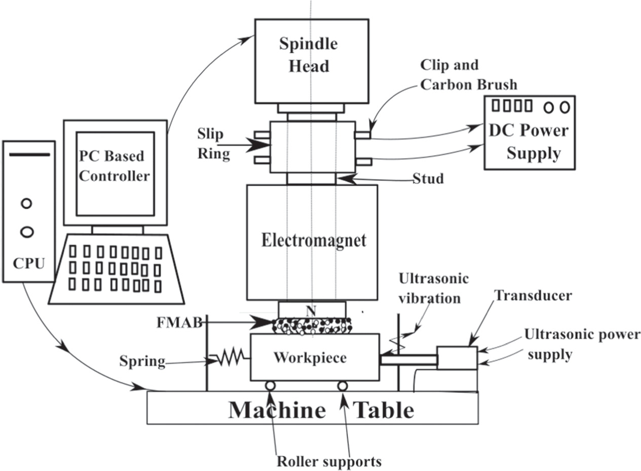
Figure 7. Ultrasonic assisted magnetic abrasive finishing setup.
Download figure:
Standard image High-resolution image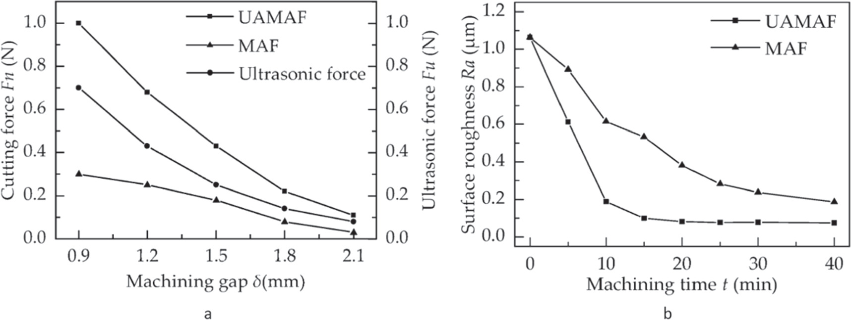
Figure 8. Comparison of (a) cutting force (b) surface roughness between MAF and UAMAF [71].
Download figure:
Standard image High-resolution imageIn conclusion, UAMAF offers superior surface quality, shorter processing time, higher material removal rate, and precise process control compared to traditional MAF for difficult-to-machine and non-magnetic materials. Ma et al [71] compared MAF and UAMAF and reported 2 to 4 times higher cutting force in UAMAF than traditional MAF, which decreases with increasing machining gap due to energy loss shown in figure 8(a). They achieved a surface roughness reduction of about 59% compared to MAF.
UAMAF method has various advantages over conventional finishing processes. Compared to traditional MAF, the UAMAF process reduced abrasive wastage and energy consumption due to increased process efficiency [123, 124], thereby, producing less impact on the environment.
3.2. Chemo-assisted magnetic abrasive finishing
The chemo-assisted magnetic abrasive finishing (CAMAF) technique was developed to accelerate the MAF process and resolve the shortcomings of chemo-mechanical polishing (CMP) [125] and the MAF process. The hybrid process integrates the advantages of both CMP and MAF processes, suitable for silicon wafers [126], Inconel [114], and other difficult-to-machine materials. In the chemical process, peaks on the surface of the material are dissolved, and a soft layer of the material will be generated (passive layer). Subsequently, MAF easily removes the passive layer. Pandey & Pandey [92] developed a CAMAF process for finishing silicon wafers and analyzed the impact of input parameters, namely working gap, percentage weight of KOH, mesh size, and polishing speed on the surface roughness. Figure 9 illustrates the surface roughness values for different trials. Sihag et al [127] investigated the use of H2O2 chemicals in UAMAF and its impact on MAF for tungsten workpieces. They reported that rotational speed had the greatest impact on the percentage change in surface roughness (37.7%), followed by abrasive weight percentage (27.74%), working gap (16.12%), and H2O2 concentration (13.75%) as shown in figure 10. Overall, 79.50% improvement in surface roughness was reported at optimum level of input process parameters. Anjaneyulu and Venkatesh [128] performed chemo-UAMAF on Hastelloy C-276 and found that surface roughness was improved by 98.3% from initial Ra = 1.3 μm to Ra = 0.0224 μm with maximum material removal of 22.19 mg.

Figure 9. Surface roughness variation at different experimental trial [92].
Download figure:
Standard image High-resolution image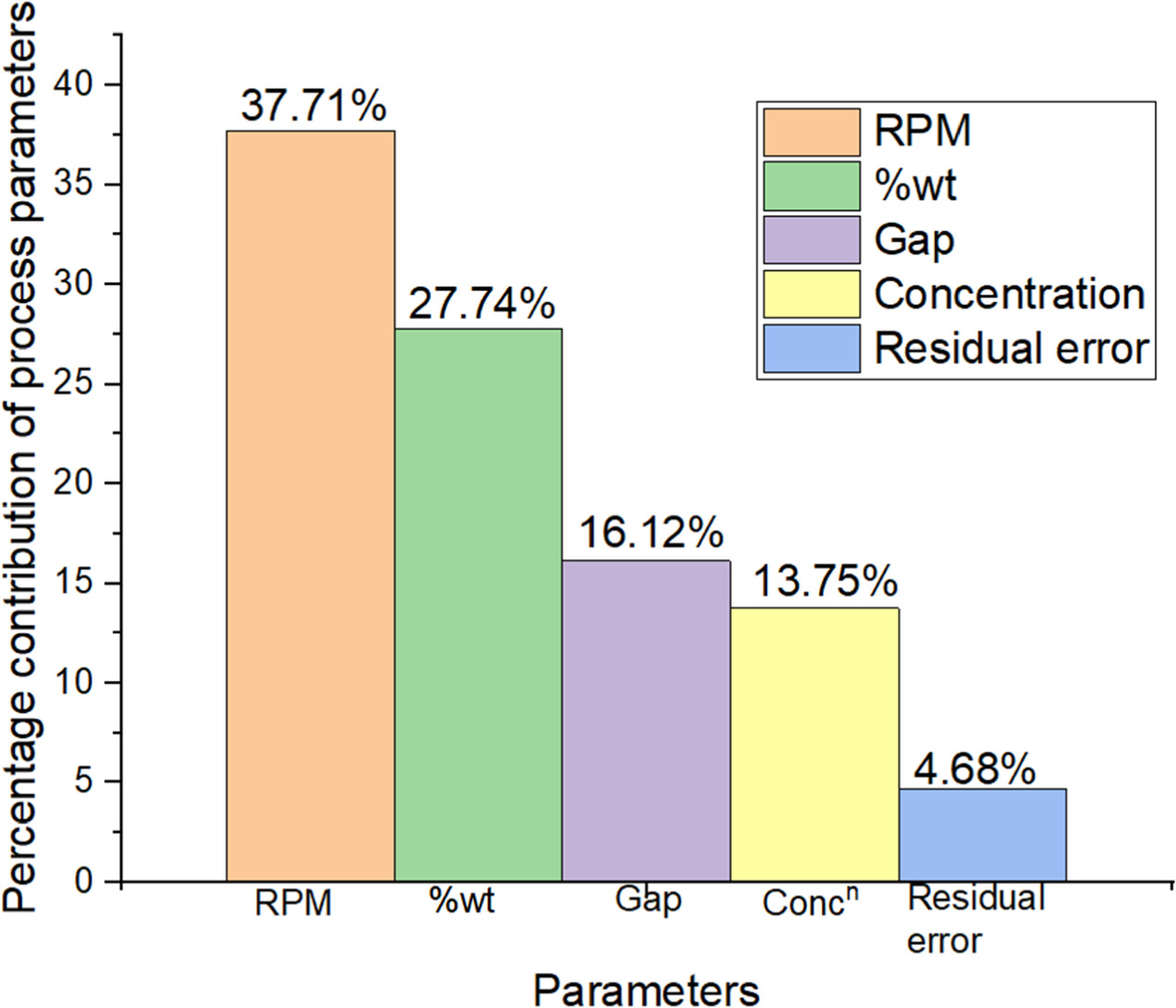
Figure 10. Percentage contribution of process factors on ΔRa [127].
Download figure:
Standard image High-resolution imageIn conclusion, CAMAF improved the efficiency of the traditional MAF process. However, the chemical used in the process may not suitable for all materials and machines since it may contain hazardous or toxic substances that require proper handling, storage and disposal to avoid environmental contamination [129, 130]. Selecting less toxic, biodegradable or readily recyclable chemicals can reduce the environmental risks. Moreover, continuous research and development efforts are also necessary to optimize the CAMAF process. Further, to solve the environmental issue, a closed-loop control system of chemicals protects the machine components from the chemicals by making handling them easy.
3.3. Electrochemical magnetic abrasive finishing
Researchers synchronized MAF with electrochemical machining and developed hybridized electrochemical magnetic abrasive finishing (EMAF) setup as shown in figure 11. This overcame the issue of the decrease in efficiency of MAF in case various difficult-to-machine metals, superalloys and non-magnetic materials such as Al2O3 composite, 316L, SUS304 stainless steel etc [10, 107, 131, 132]. During the EMAF process, the electrochemical reaction is responsible for flattening the peaks by anodic dissolution and forming a passive layer on the workpiece. The passive layer formation mechanism in the electrochemical process is shown in figure 12(a), and the whole EMAF process is shown in figure 12(b) [64]. This occurs when the workpiece surface interacts with the electrolyte ( ). Ionization reactions take place represented by equations (4) and (5) play a significant role [131].


Cations migrate toward the cathode, and anions move toward the anode, guided by the ionization tendency of cations and the discharge capacity of anions, reactions (6) and (7) take place at the cathode and anode [131]


Hydrogen gas ( ) is generated at the cathode, and oxygen gas (
 ) is produced at the anode. The generated oxygen reacts with metal ions, resulting in the formation of a passive layer. This passive layer remains in contact with the workpiece surface under low current densities supplied in this hybridized process. However, during the EMAF process, the passive layer experienced local abrasion due to MAF. This abrasion leads to abrasion-assisted-dissolution, causing the rapid removal of the locally de-passivated metal surface. Subsequently, further passivation occurs, as depicted in figure 12(b) of the EMAF process [64]. There is no physical contact between the workpiece and the tool (electrode) throughout the finishing process. Therefore, the electrode does not disintegrate and enhances the service life [133, 134]. Sun and Zou [135] proposed EMAF on stainless steel SUS304. In the first 4 min, EMAF was performed, and then traditional MAF was performed for the next 26 min to remove all the passive layers formed during EMAF. They found an improvement in surface finish (up to 20 nm) and MRR (9.75 times) than traditional MAF. Judal and Yadava [136] examined how variations in electrolytic current, magnetic flux density, and rotational speed of the workpiece influence material removal and surface roughness during the EMAF process. Fang et al [137] examined the impact of the magnetic field on the movement of ions and chemical reactions. They observed negative ion movement towards the workpiece in a cycloidal fashion when the magnetic field was present, enhancing the surface finish. In conclusion, EMAF combines the capabilities of electrochemical machining and MAF to provide a versatile and effective process for achieving a good surface finish. In conclusion, EMAF improved the process efficiency of the traditional MAF process. However, it has almost similar environmental issues as CAMAF, except the chemical replaced by the electrolyte in combination with low-intensity current is used, which is less severe to an environmental issue than CAMAF.
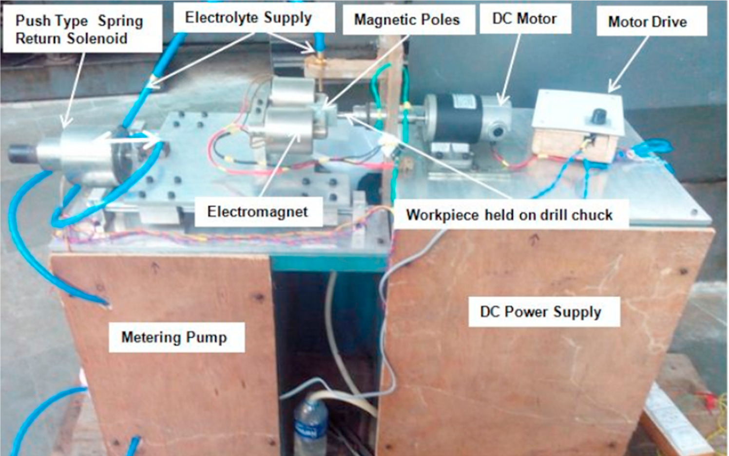
Figure 11. Pictorial view of EMAF [138].
Download figure:
Standard image High-resolution image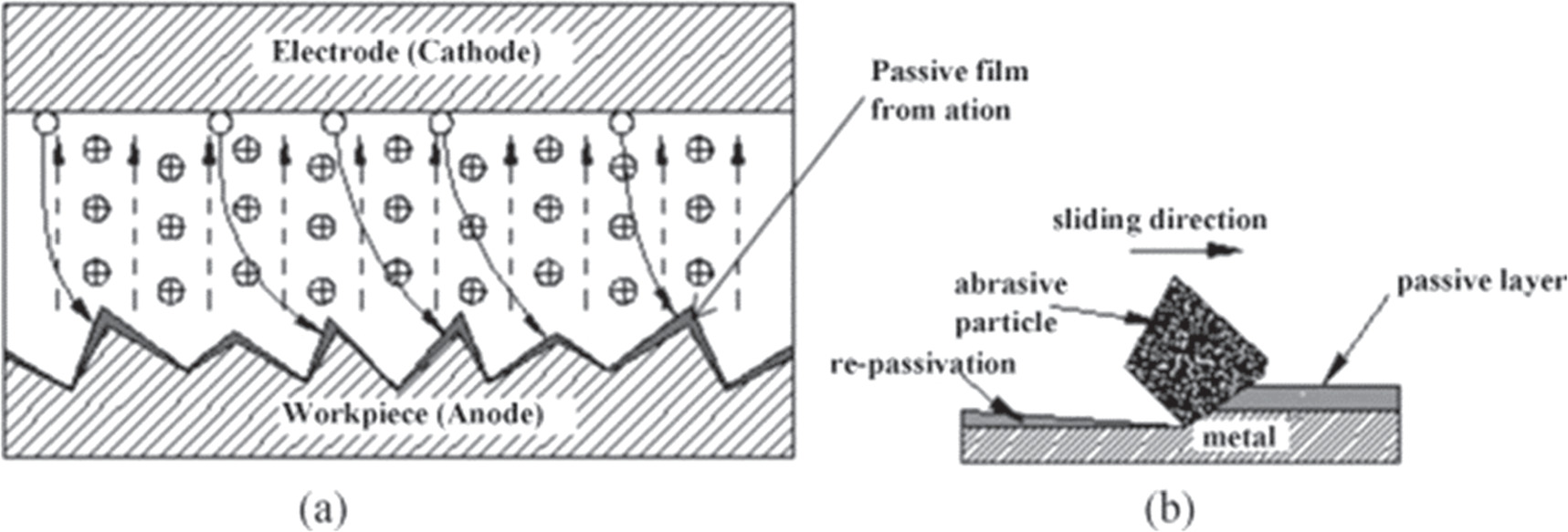
Figure 12. (a) Passive film formation and (b) complete passive film removal and re-passivation [64].
Download figure:
Standard image High-resolution image4. Modeling and simulation of MAF process
To understand the MAF process behavior, a mathematical or theoretical model must be built to analyze the influence of various process factors on response variables, such as surface roughness, material removal rate (MRR), and finishing force. This model allows for optimization of process parameters and reduces the need on costly trial-and-error experiments, providing valuable insights into the interactions between different parameters. In general, the model provides the details, which helps in understanding the characteristics of the phenomena that is taking place in the actual scenario. After modeling, the equations are solved with constrains of boundary conditions for simulating the model. Simulation provides the behavior of the actual system.
4.1. Modeling and optimization of MAF
Surface roughness and MRR are the critical factors for evaluating the finishing processes. Thus, it is important to predict or visualize how the input process parameters along with the working environment, affect the response parameters of the process. MAF aims to obtain a superior surface finish with minimum material removal, like other finishing processes. This will ensure that shape and size inaccuracy in a part can be minimized [118]. The magnetic field strength in MAF is responsible for the forces acting by the FMAB on the specimen to control the MRR. Kumar and Yadava [47] performed mathematical modeling based on Maxwell's equation for predicting the magnetic flux generated and the magnetic forces. Further, they found that magnetic flux density significantly affects the rise in temperature compared to rotational speed. Mishra et al [139] developed a mathematical model to anticipate the MRR for the UAMAF process. They considered both the continuous and temporary removal of materials that occur at the same time during the operation. Unlike steady state, transient MRR includes initial surface roughness. Different researchers developed mathematical models for predicting normal and tangential forces for MAF process. The models developed by Shukla et al [75] and Misra at al. [140] had a high degree of consistency with the actual experimental values of forces. Gao et al [93] developed a model for predicting MRR based on depth of indentation, finishing trajectory, and abrasive particle number.
Empirical models are also in practice for predicting output parameters based on input process parameters. However, the development of an empirical model reported by various researchers requires experimental data and knowledge of the phenomenon rather than theoretical understanding. From experimental data, Chaudhari & Judal [141] developed a regression model for surface roughness and MRR. They used multi-objective optimization techniques to find the optimal parameters of the developed model and verified the experimental result. Mulik et al [141] established a regression model for finishing force and torque in the case of UAMAF. The following parametric equations (8) and (9) were derived for the force and torque, respectively, from the experimental data.


The variables 


 and
and  are voltage supply, electromagnet rotational speed, percentage weight of abrasive, working gap, and pulse duration.
Soft computing techniques are also becoming popular for the optimization of MAF. Few researchers already reported some techniques for solving complex problems based on artificial intelligence and natural selection to provide results that are more precise. Ahmad et al [53] used ANN-GA to enhance the process performance of MAF and compared to the result with the conventional Taguchi-ANOVA analysis. The results obtained by ANN-GA exhibited a 7% improvement compared to the Taguchi-ANOVA analysis. Various soft computing techniques utilized by researchers are listed in table 3.
Table 3. List of various optimization techniques used in MAF.
| Modeling and optimization technique | References |
|---|---|
| Genetic algorithm (GA) | [89, 92, 142, 143] |
| Particle swarm optimization (PSO) | [144, 145] |
| Response surface methodology (RSM) | [94, 108, 146, 147] |
| Taguchi robust design | [92, 107, 142, 147] |
| Jaya algorithm | [148] |
| Artificial bee colony (ABC) | [149] |
| Grey relational analysis (GRA) | [150] |
Both numerical and empirical models are robust techniques, but their accuracy for prediction depends on the type of problem and conditions. Numerical models in machining/finishing struggle to anticipate beyond given boundary conditions, dynamic problems, mesh size and do not consider the effect of agglomeration of abrasive particles [151, 152]. Due to computer constraints, they may miss the key factors or simplify essential variables. Empirical models based on observed data could be biased, misinterpret the cause and effect, and become obsolete after overextending the range of selected variables. Both have limitations; therefore, it is essential to use their outputs carefully in finishing decisions while understanding their strengths and drawbacks.
4.2. Simulation in MAF
Various numerical studies of the MAF process were carried out to predict the effect of shapes, slot/without slot in magnet, and magnetic field distribution on the surface finishing of sample during the MAF. Srinivas et al [153] performed a numerical study to evaluate the effects of four different magnets, namely, fan-shaped, arc-shaped, ring-shaped and electromagnet magnetic poles on the efficiency of MAF. In their research, authors considered the cylindrical workpiece for the analysis. The results of their article showed that an arc-shaped magnetic pole gave maximum MFD; whereas ring-shaped magnetic pole showed minimum MFD. Jayswal et al [154] investigated the effect of the slot (on the lower end of an electromagnet) on the surface finish of the sample. They found that magnetic field concentration in the slot increased forces around it and got a better surface finish than without slot in less time (Refer figures 13(a) and (b)). Cui et al [155] performed numerical analysis of MAF on curved surfaces. They analyzed the effect of slot angle on magnetic field strength and observed that magnetic field strength increases with a decrease in edge angle. Trapezoidal slot with 75° edge angles on a spherical magnetic pole gives better field strength than a cylindrical. Mishra et al numerically analyzed the temperature and magnetic flux distribution between the workpiece and FMAB interface. They reported that the predicted minimum and maximum temperatures were found to be in the range of 34℃−51℃, which did not affect the workpieces surface finish and surface texture [58]. Singh et al [156] studied the influence of electric current and MFD on temperature for Al-6060 and stainless-steel workpieces using the FEM. They found that the resulting temperature rise (due to finishing) for the stainless-steel workpiece was higher than Al-6060. This is due to low conductivity of stainless steel and magnetic characteristics compared to Al-6060.
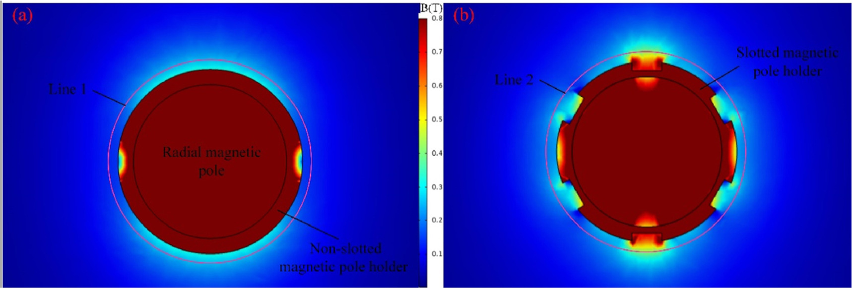
Figure 13. FEA simulation results of radial magnetic column. (a) Non-slotted magnetic pole socket, (b) slotted magnetic pole socket.
Download figure:
Standard image High-resolution image5. Challenges in advancing the MAF process for future work
After the critical review of the literature related to the MAF process, the authors observed the following challenges:
- (i)Most of the literature available in the MAF was related to the finishing of plane, internal, and external curved surfaces of a cylindrical workpiece. However, the finishing of free-form surfaces using MAF is a less explored area. Finishing engineering parts having internal grooves and intricate shapes, such as gears and molds are less explored using MAF. In addition, finishing free-form surfaces while maintaining constant working gap throughout the surface using Computer Numerical Control (CNC)-controlled tool movement and proper fixture design according to surface profile is still less explored.
Integrating a CNC system with MAF helps in achieving precise match between the brush shape and intricate free-form surface. CNC controlled tool movement [157] and well-designed fixtures hold immense potential for precise and efficient MAF of complex, free-form surfaces. CNC program ensures the consistent brush movement for uniform finishing across free-form low-depth geometries [158]. Lin et al (2007) demonstrated achieving surface roughness up to 0.1 μm on free-form surface of stainless SUS 304 workpiece using CNC-controlled MAF [36]. Lack of automation in the MAF process is the reason for not being used in industry on large scale. MAF requires a closed-loop control with a feedback system, as shown in figure 14. This will ensure better control over the output variables by tuning input process parameters based on the feedback signals. Automation in a mechanical system can be achieved by introducing some components of control hardware e.g., the controller, which acts as the brain of automation. It can be programmed according to the need of process and control panel design, which is an assembly of various control hardware such as motor drivers, power supply, and programming logic controllers [159]. Multi-axis control allows the tool to access difficult areas like sharp edges and deep cavities. Alam et al, 2019 used the CNC part program to control the supply of magnetizing current so that the finishing force is adjusted according to the profile of the 3D surface of the test specimen to get a uniform surface finish and compare the surface roughness result between manual and in-process control [160]. Well-designed fixtures stabilize the workpiece, control abrasive distribution, and provide tool accessibility, further enhancing the accuracy and efficiency of the MAF process.
- (ii)It has been observed from the literature that the efficiency of MAF for surface finish and MRR for difficult-to-machine materials, such as ceramics, superalloys and glasses, was low. Therefore, enhancing the efficiency of the MAF for above materials by hybridizing MAF with other processes, such as electrochemical, and chemo-assisted processes, are another possible opportunity.
- (iii)Real-time monitoring and adaptive control of MAF process is less explored area and has a promising future in view of industry 4.0. This will not only help to reduce human intervention but also reduce finishing time and improve the efficiency of the process.
- (iv)More investigation is needed in the area of preparation of bonded magnetic abrasive particles with different methods, such as sintering, gas atomization, rapid solidification, etc at different compositions of abrasive and ferromagnetic particles and at different compaction pressures to increase MRR and high-quality surface finish. Identification of a more efficient method for the development of bonded abrasive particles among the available methods is to be explored.
- (v)In the majority of literature, either permanent magnets or electromagnets with direct current were used. An electromagnet with direct current was found to be better than permanent magnets. However, flux leakage and coil overheating in the electromagnet is possible. A leaked magnetic field diminishes finishing quality and wastes energy due to uneven magnetic field distribution and increased power consumption. However, overheated coils weaken the field, increases damage risk, and pose safety hazards due to excessive heat buildup in the coils, raising their resistance and leading to insulation breakdown and, short circuits leading to fire risk [161]. These issues can be addressed using optimized coil design, specialized core materials such as soft laminated iron, and shielding to confine the magnetic field to enhance the field strength and minimize flux leakage [50]. Moreover, implementing efficient cooling systems like forced air or liquid cooling can effectively dissipate heat from the coils, maintaining safe operating temperatures. Duty cycle management may also prevent overheating and ensure long coil life.
- (vi)The influence of an alternating magnetic field generated by alternating current has the potential to improve the surface finish efficiency. Therefore, this area is to be explored to understand the exact behavior of force directions and the behavior of MAPs.

Figure 14. Control of output process parameters by providing a feedback signal to input parameters.
Download figure:
Standard image High-resolution image
6. Conclusions
In this paper, review of literature related to MAF process is presented to show the recent trends in MAF. The literature is critically analyzed, and the potential areas to be explored are presented. The conclusions drawn from the literature are summarized below. From the literature, it can be observed that the MAF process was used for finishing both magnetic and non-magnetic materials. MAF was also used for finishing or deburring superalloys, ceramics, and biomaterials.
The selection of machine tools and attachments for the MAF process depends on the nature of the surface to be finished. The abrasives used in MAF were either bonded or un-bonded MAPs. The quality of the surface generated, MRR, and flexible magnetic abrasive brush stiffness in the MAF process depend on the proper selection of process parameters. MAF can be combined with other un-conventional processes to enhance the efficiency of the process in terms of better material removal and surface finish, especially for difficult-to-finish materials.
Finite element simulation and other modeling techniques were used in the literature to predict the range of optimal process parameters, thereby reducing the number of trial runs. Soft computing techniques were also used for the optimization of the MAF process.
However, it can be possible to use the MAF process for finishing additive manufacturing products, aiming to improve end-product performance efficiency.
Data availability statement
No new data were created or analysed in this study.
Declaration and conflicting interests
The authors have stated that there are no possible conflicts of interest that could influence the research, authorship, or publication of this article
Funding
The authors state that they did not receive any financial aid, grants, or other forms of support during the preparation of this manuscript.