
Abstract
This paper presents a first concept of a new biomimetic transradial prosthetic arm design, called 'MataPro-1,' that features a 3D-printed hand bone structure that mimics the shape of human finger phalanges and palm bones, flexible elastic joints, artificial muscles, and silicone flesh that covers and protects the internal components, provides restoring force, enables better gripping capability, and appears cosmetically realistic. The artificial muscles that actuate MataPro-1 are shape memory alloy (SMA) wires, which ensure effective grip strength for many everyday objects, without causing any noise. In order to avoid the need to cool SMA wires in the small volume of the fingers, the SMA wires are not routed through the finger phalanges. The SMA wires are spooled in the forearm, cooled by a fan only during the finger restoration process, and are connected to steel wires that are routed through the finger phalanges. The finger restoring force provided by the flexible joints and silicone flesh acts as bias force for SMA wires, avoids the need for antagonistic SMA wires, and speeds up the finger restoration process. The control system of MataPro-1 is intuitive and non-invasive achieved by voice recognition phone application, or an EEG headset that monitors brainwaves and facial expressions. MataPro-1 was successful in gripping different objects of various shapes, weights and sizes in multiple different gripping positions.
Export citation and abstract BibTeX RIS
1. Introduction
Limb loss plagues over a million individuals in the US alone [1], and it is a disability that greatly affects quality of life, from an inability to perform daily routines to serious depression and other forms of mental illness. Prostheses offer hope to many people by allowing for regained functionality with the missing limb. Unfortunately, modern prostheses can range in price from thousands of dollars, for even a purely cosmetic replacement, to tens of thousands of dollars for fully functional myoelectric prostheses. Fortunately, the advent of additive manufacturing through the increased availability of 3D printing has allowed for an influx of new designs of prostheses in a market that is sorely in need of refurbishment [2].
Recently, multiple review articles have been published on the current status and advancement of prostheses. Belter et al [3] made a detailed analysis of the mechanical characteristics of different anthropomorphic prosthetic hands, including the iLimb® (Össur, Iceland), Bebionic®(Ottobock, Germany), Michelangelo (Ottobock, Germany) and Vincent (Vincent Systems GmbH, Germany) prosthetic hands. Phillips et al [4] reviewed current body-powered, electric and myoelectric upper limb prosthesis designs available to lower-middle-income countries (LMICs). Saikia et al [5] in their review focused on the advancement and development of biomimetic based dexterous prosthetic hands. Vujaklija et al [6] in their review focused on the new technologies and techniques accompanying the latest upper limb prostheses. Ten Kate et al [7] provided an overview of existing 3D-printed upper limb prostheses, including the benefits and drawbacks of all designs (58 devices). Controzzi et al [8] in their review, compared the hand design key features, such as hand kinematics, actuation principle and mechanisms, anthropomorphism, transmission, sensors and manufacturing. Cordella et al [9] presented a literature review focused on the needs of upper limb prosthesis users. Andrés et al [10] made a comparison between tendon and linkage prosthetic transmission systems. They concluded that the tendon-driven model achieved a greater quantity of successful grasps compared to the linkage-driven model. Tendon-driven hands are dominant because of the fewer number of parts to be printed, the easier assembly for a nonexpert user, and the advantages in pursuit of lightweight devices. The advanced anthropomorphic prosthetic hands available in the market nowadays, although capable of high forces at high actuation speeds and great versatility, encounter high rejection rate by the users due to their rigidity, heavy weight, noisy operation, low grasping stability, and the robot-like motion of the fingers. In addition, the electric motors used for actuation require complex transmission systems and are difficult to manufacture and assemble [11–13].
Shape memory alloy (SMA) materials are among the most suitable smart materials that can be used in prosthetic devices as actuators, since they provide large force and strain levels with very low weight [14]. When exposed to heat, usually via Joule heating, SMA materials (such as Nickel-Titanium alloys or 'Nitinols') undergo a phase transformation, from the Martensite phase to the Austenite phase, that results in contraction. Commonly, SMA actuators are in the form of wires, and this contraction is used in actuation. Temperature-induced phase transformation of SMA materials, and the consequent contraction, are accompanied by a change in electrical resistance that can be correlated to strain, load, and material fatigue. Hence, in principle, it is possible to measure electrical resistance during actuation and relate it to the length of the wire, in order to reconstruct the mechanical deformation of the SMA without introducing additional electromechanical transducers in the system. This simultaneous actuation and sensing feature is often referred to as 'self-sensing' [15]. Shape memory alloys have been used in many applications, such as aerospace morphing structures [16, 17], neurology and neuromuscular rehabilitation [18], and bioengineering and biomedical technology [19]. Shape memory materials have also been used in prosthetic arm designs [20–26] and soft grippers [27–29]. Although very attractive as silent, powerful and lightweight actuators, SMAs have some drawbacks that should be considered in design. These drawbacks include (1) high energy consumption that might increase the overall weight of the SMA actuation system, (2) high temperature that the actuators much achieve to operate, which might be damaging to surrounding components, and (3) relatively long cooling time required to return the wires back to their original configuration once the heating action is stopped; This limits the actuation frequency at which SMA actuators can operate, and usually requires a cooling system, such as a fan or array of fans, to be used.
Kim et al [20] developed a prosthetic hand based on an artificial finger design as a smart soft composite (SSC) actuated using embedded SMA wires. A sensitivity analysis has been conducted for this design to investigate the effect of the different design parameters on finger deformation [21]. The geometrically nonlinear finite element composite beam model in [30] was used in this analysis. This composite finger design lacked the humanoid appearance, since it is more like a plate than a finger. Li et al [22] also developed a soft finger with embedded SMA fibers and a variable stiffness mechanism, but the design also lacked the humanoid appearance. Taylor and Au [23] developed a prosthetic arm design with SMA wires to actuate the fingers and added position sensors and a PID controller. They also introduced a fan to increase the cooling rate of the SMA via forced convection. Extension springs were used to provide release force as well as bias force required to deform the SMA wires back to their relaxed configuration. Shape memory alloy plates or ribbons were used by Engeberg et al [24] to actuate an anthropomorphic finger design. In order to increase the cooling rate of the SMA plates using forced convection, the design was adapted to operate underwater, which rendered the design impractical for many users. Simone et al [25] presented a three-finger prosthetic gripper with bundles of thin SMA wires running along the phalanges to actuate the fingers. Since SMA wires are heated during actuation, they had to be routed through tiny Teflon tubes in the finger phalanges to prevent any damage to the plastic material of the phalanges. This complicated the manufacturing and repair processes. Also, to allow for better cooling of SMA wires during finger restoration, the finger phalanges were designed to have open sides, so the SMA wires became exposed to the outer environment in this design, which makes them more susceptible to damage. Wu et al [26] used twisted and coiled polymeric (TCP) nylon artificial muscle wires to actuate their prosthetic device. Although TCP wires can have larger strain levels than SMAs, their generated forces are much smaller than that of SMAs, so gripping heavy objects would be impossible. This design, like many other tendon-based prosthetic arm designs, lacked a 'flesh' material to protect the internal components and provide restoring force. TCP wires were also used by Saharan et al [31] to actuate a 3D-printed compact, lightweight, inexpensive upper extremity orthotic device, called 'iGrab.' The design is mainly made of rings that surround the user's finger joints, and the TCP wires are routed through tiny holes in these rings to actuate the device and assist the user in gripping objects.
This paper presents a first concept of a biomimetic transradial prosthetic arm design, called 'MataPro-1,' that features a 3D-printed plastic bone structure that mimics the shape of human hand bones, flexible elastic joints, a silicone 'flesh' cover that protects the internal components, provides restoring force, enables better gripping capability, and appears cosmetically realistic. MataPro-1 is actuated by SMA artificial muscle wires to allow for multiple different gripping positions. The SMA wires are spooled only in the forearm and are connected to steel wires that are routed through the finger phalanges. This design solution avoids routing the SMA wires through the phalanges of the fingers, hence the cooling process can be localized in the forearm, using a fan directed to the SMA wires and operates only during the finger restoration action. This design solution also allows the finger phalanges to be totally covered by outer skin, and the actuation wires fully protected from the outer environment. Furthermore, there is no need to integrate tiny Teflon tubes to the 3D printed phalanges (as was done in [25]), since no hot wires are touching these plastic pieces. The main control method used in most prostheses depends on getting signals from myoelectric sensors placed on the user's limb residual to control the hand when the muscles contract or become in tension. Many users experience fatigue due to these muscle movements [32]. Hence, control of MataPro-1 prosthetic arm is achieved by voice recognition software on a mobile phone, or an EEG headset that monitors brainwaves and facial expressions. Both control methods are intuitive and non-invasive.
The rest of the paper is organized as follows: The whole design is explained in section 2, followed by the mathematical model used to guide the design and help finding the required SMA wire actuator length in section 3. The description of the dual control system is in section 4. Section 5 provides more details on manufacturing, and section 6 presents some testing that was done on the proposed design. Conclusions are summarized in section 7.
2. Design
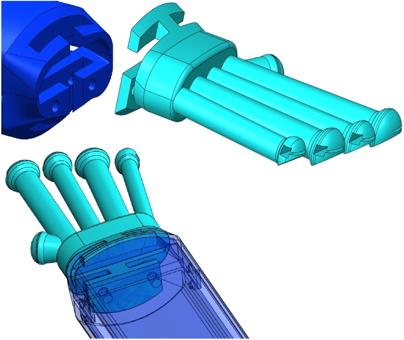
Figure 1 shows the CAD model of the proposed transradial prosthetic arm design, MataPro-1. The fingers are made of 3D printed Polylactic Acid (PLA) distal, middle and proximal phalanges connected with 3D printed flexible Thermoplastic Polyurethane (TPU) interphalangeal and metacarpophalangeal joints that allow for finger rotation and provide finger restoring force. Figure 2 shows the details of the finger design.
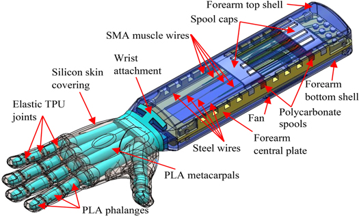
Figure 1. CAD model of the entire proposed SMA-based transradial prosthetic arm (MataPro-1).
Download figure:
Standard image High-resolution image
Figure 2. Index finger skeletal design.
Download figure:
Standard image High-resolution imageThe bones of the fingers have inserts for the dumbbell-shaped flexible joints and a wormhole for the steel muscle wires that are routed through the fingers. The wires are crimped at the distal phalange bone. The bones also have 45° cuts to enable larger finger rotations. The index and ring fingers are similar in length. The finger bones are connected to a 3D printed palm structure that resembles the shape of the human metacarpal bones as shown in figure 3. The palm is attached to the forearm through a wrist attachment shown in figure 3. The whole arm is covered by silicone skin that protects all internal components, facilitates gripping different objects through friction, and contributes to the restoring force that returns the fingers back to their original configuration during the finger restoration process. The silicone 'flesh' covering is made of EcoflexTM 00-35 (Smooth-On, USA), which was poured in a 3D printed mold that encloses the whole hand internal structure, taking the desired shape of the hand. This rubbery material is skin-safe and can stretch many times its original size without tearing, and then rebounds to its original form without distortion.
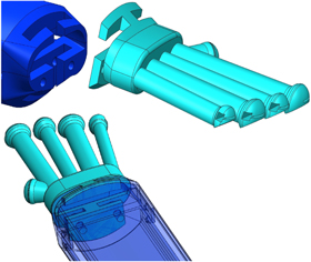
Figure 3. Wrist attachment and palm design.
Download figure:
Standard image High-resolution imageSimple mechanical tests of manually rotating the fingers and leaving them to return to their initial undeformed shape on their own, demonstrated the strong effect of the elastic joints and skin on the restoring force and time. This avoids the need to add antagonistic SMA wires to return the fingers to their initial undeformed configurations as was done in many previous designs ([24, 25]). Finger restoring force act as bias force required to deform the SMA wire actuators back to their initial length during the cooling process. Increasing finger restoring force leads to decreasing finger restoring time (time needed for the fingers to return back to their initial configuration), hence increases the maximum frequency of actuation. Finger restoring force is a function of the shape and material of both the flexible joints (which act as hinges) and the outer skin around the joints. The main geometric design parameters are the length and thickness of the flexible joint connecting section (Lj , tj ), shown in figure 2, and the thickness of the Silicone skin around all joints in each finger (ts ). ts might vary from finger to finger or from joint to joint in the same finger. Increasing tj and ts will generally increase the finger stiffness, which will in turn increase the finger restoring force, but will limit finger rotation with the available actuation force. So, there is a trade-off between finger rotation and finger restoring force (or finger stiffness). Increasing skin thickness in the whole hand will also lead to increasing the weight of the hand. For the proposed design, Lj was selected to be 1 cm, which ensures that each phalange bone can rotate 90° relative to the neighboring phalange, and tj = 1 mm. Due to the presence of skin, the angle of rotation of each phalange will not reach 90°, as will be discussed in section 6, but only 75°. 90° phalange angle of rotation (which makes 270° fingertip total angle of rotation) is only needed when making a fist with nothing grasped. However, typical daily use does not require a 'fist' grip, but rather an effective grip around an object, which is what was achieved by the proposed design, as will be shown in section 6. In terms of materials, 3D printed TPU with 100% infill was used for the flexible joints. Three different skin materials were tested, namely: EcoflexTM 00-35, EcoflexTM 00-20 and Dragon skinTM (Smooth-On, USA). Upon testing, EcoflexTM 00-35 was preferred as it gave better balance between finger rotation and finger restoring force. The effect of all geometric and material properties of the flexible joint and skin on finger rotation, restoring force and time will be the focus of a future study, and will not be addressed further here in this first concept work.
The forearm is made of a 3D printed PLA central plate that holds the spools of the SMA actuation system, and possibly a locking mechanism, using spool seats that enable changing the location of the spools as shown in figure 4. The central plate is covered by top and bottom shells that can be 3D printed and possibly covered by a layer of fiber-reinforced composite laminate for strengthening. The bottom shell secures the cooling fan that is used to cool the SMA wires only during the relaxation action to accelerate finger restoration. The top shell has vents for air-circulation.
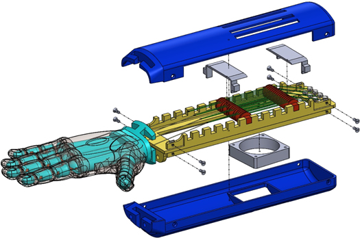
Figure 4. Exploded view of MataPro-1.
Download figure:
Standard image High-resolution imageThe spools are 3D printed of polycarbonate, because of its high strength, impact resistance, and heat resistance, compared to other 3D printing materials. Polycarbonate is also lightweight, flame-retardant, high-temperature and electric insulator material, which makes it the best material for the spools which are the only components that are in touch with the SMA wires. Figure 5 shows one of SMA wire actuator loops wound around the two spools that feature grooves to guide the SMA wire path in each loop. Four separate loops of SMA wire were used to actuate the thumb, index, middle fingers separately, and the ring and pinky fingers together. Each SMA wire actuator loop starts at a terminal block at the end of the central plate, makes one full loop around the two spools, reaches the crimp that holds the end of the steel wire, goes back and makes another full loop around the two spools, before returning back to the terminal block where it is mechanically and electrically grounded. Both ends of each SMA wires are screwed to the central plate as shown in figure 4. These retaining screws are used to adjust the tension of the wires. This is important because during the few early cycles of SMA wire actuation, the wires get trained towards the most fitting configuration for the specific load, strain and temperature characteristics during the performed task. So, tension readjustment after these few early cycles (10–20 cycles) would always be necessary. The used SMA muscle wires are Flexinol® 0.02" diameter (0.51 mm) wires (DYNALLOY, Inc., USA) . This is the largest SMA wire diameter available at DYNALLOY and provides the largest maximum pull force of approximately 35 N. SMA-based prosthetic hands usually feature low gripping forces, so this wire diameter was selected to maximize the resulting gripping force and finger rotation. The length of each SMA wire actuator is calculated based in the mathematical model in section 3. Due to this SMA wire loop around the spools, the stroke of the actuator would be half the change in length of the SMA wire, but the applied pull force will be doubled (35 N × 2 = 70 N).

Figure 5. One SMA wire actuator wound around the two polycarbonate spools (the other three wires are hidden).
Download figure:
Standard image High-resolution imageThe locking mechanism is not covered in this first principle work but will be considered in future research. This locking mechanism would be placed in the forearm aft of the wrist attachment, and would be used to lock the steel wires in place once the fingers have rotated to grip an object or form a gesture based on a received command. When the SMA wires get deactivated and start cooling and going back to their original length, the fingers would not move because the locking mechanism is on. Once the controller receives a finger 'relax' command, the locking mechanism would unlock the steel wires, and the fingers would be retracted quickly to their initial configuration due to the restoring force provided by the elastic joints and Silicone skin. A locking mechanism design for TCP actuator wires was proposed by Saharan and Yadasse [33].
3. Mathematical model
The mathematical model used to calculate SMA wire length required to achieve full deflection of the fingers is based on the mathematical model in [26]. This model uses the geometric parameters in figure 6 as well as the ratios of the proximal interphalangeal (PIP) and distal interphalangeal (DIP) joint rotations to that of the metacarpophalangeal (MCP).

Figure 6. Geometric parameters of the analytical model.
Download figure:
Standard image High-resolution imageFor given lengths  offset distance of the artificial muscles from the finger's central axis (e), as defined in figure 6, and phalange deflection angles θ1, θ2 and θ3, the required muscle wire stroke is expressed as

where


The coordinates of the fingertip  from a global coordinate system located as the MCP joint, are the summation of the components of the PIP, DIP and fingertip (FT) coordinates measured from local coordinate systems at the MCP, PIP and DIP, respectively.

where 
 and
and  are the distances between MCP and PIP, PIP and DIP, and DIP and FT, respectively.

Since all hinge cuts were designed to be at 45° as mentioned earlier (check figure 2), the following geometric relations are satisfied, reducing the number of independent variables by three:

This also defines the lengths 
 and
and  for given e and phalange lengths. As e increases,
  decreases, so the value of e was selected to be as far as possible from the finger's central axis, but in such a way that ensures enough material around the wormholes of the actuating steel wires to prevent any damage during actuation. e was taken to be 5 mm.
 and
and  depend on the length of the TPU elastic hinges, Lj
, and their placement in the phalanges. The joint grooves in the phalanges were placed to ensure the hinges are holding the phalanges together properly without slipping or damage upon actuation. As mentioned earlier, Lj
= 1 cm.
depend on the length of the TPU elastic hinges, Lj
, and their placement in the phalanges. The joint grooves in the phalanges were placed to ensure the hinges are holding the phalanges together properly without slipping or damage upon actuation. As mentioned earlier, Lj
= 1 cm.
The angles 
 and
and  are not independent. The relationship between them heavily depends on the geometric and material properties of the model. Wu et al [26] assumed a constant relationship for their finger model as
  and
and  where
where  and
and  are experimentally determined constants called interphalangeal joint coordination parameters. For the proposed model, it was found that these parameters are varying as the finger deforms from the initial configuration to the final configuration. A video of the full deformation of each finger was taken, and frames at constant increments were analyzed, as shown in figure 7.
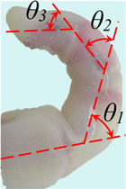
Figure 7. Sample analyzed frame from a prototype testing video.
Download figure:
Standard image High-resolution imageFull deformation here means the rotation the finger can achieve with maximum actuation force from the SMA wire actuator. A nondimensional 'deformation parameter,' denoted  was defined to represent the actuation process, where
  indicates the undeformed configuration and
  indicates the finger's fully deformed configuration. New interphalangeal joint coordination functions were then defined in terms of
  as:
as:

Notice that, unlike [26], where θ1 and θ2 were expressed in terms of θ3, here θ2 and θ3 are expressed in terms of θ1, which is a more practical choice, in the authors' opinion.
 and
and  were found to increase in a close to a linear fashion as the finger deforms. So, they can be curve-fitted and expressed as


For the index finger for example, a1
= 0.7995, a2
= 0.0097, b1
= 0.7973 and b2
= -0.0497. R2 values for the two curve fits were 0.994 and 0.919, respectively. Once  and
and  functions are obtained experimentally, the trajectories of the fingers can be plotted, and the required muscle wire stroke can be obtained for any required MCP hinge rotation angle θ1. All lengths
  in figure 6 were measured for the proposed model. For the index finger for example, l1 = 0.4, l2 = 0.8, l3 = 0.75, l4 = 0.75, l5 = 1.3, l6 = 0.7, l7 = 0.7, l8 = 1.8, l9 = 0.75, l10 = 0.75 cm. Figure 8 shows the deformation of the index finger as θ1 increases from 0 to 75° using this analytical model.
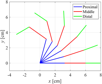
Figure 8. Computational angular rotation of the three index finger phalanges.
Download figure:
Standard image High-resolution imageThe total fingertip rotation angle is 210° when θ1 reaches 75°. For the index finger,  was found to be 1.7 cm to achieve the final configuration in figure 8 (θ1 = 75°,
  = 210°). As mentioned before, due to the SMA wire loop used, the change in SMA wire length needs to be double the stroke (
 ). Utilizing a maximum strain of 4% in SMA wire actuators, the wire lengths for all fingers can be calculated. For the index finger for example, a total SMA wire length of 85 cm, in the fully activated austenite state (shortest reference length), was required. The spooling system (shown in figure 5) with the ability to change the spool locations in the forearm facilitated adjusting the distance between the two spools to fit the SMA loop properly. Pieces of SMA wires that are longer than the calculated length were cut first. Then few actuation cycles were done, using a simple setup, to enable determining the fully activated austenite state (shortest length) as well as the fully martensite state (longest length). The wires in the fully austenite state were then cut to the required length plus an additional 5%. This extra wire length was extended beyond the retaining screws and used to compensate for any stroke losses (due to friction between the wires and the spools for example) or training losses after the first few actuation cycles in the assembled configuration. The retaining screws were used to readjust the strain of the wires.
4. Manufacturing
The first step in manufacturing the proposed MataPro-1 prosthetic arm was to 3D print all components. All finger phalanges along with the palm structure and wrist attachment can be 3D printed of PLA in one print job. The forearm central plate and top and bottom shells can be 3D printed in another job, depending on the 3D printer's bed size. Only the joints are 3D printed of TPU and the spools of polycarbonate. Finger phalanges and joints were assembled and connected to the palm as shown in figure 9(A). Steel wires are then fed through the holes of all phalanges in the five fingers and are crimped at cavities in the distal phalanges shown in figure 9(C). The two-piece hand mold, shown in figure 10, was also printed in two print jobs.
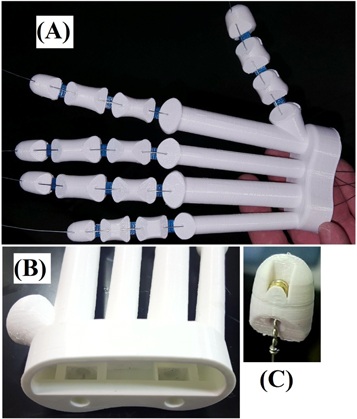
Figure 9. (A) 3D printed finger phalanges connected with flexible TPU joints and assembled to the palm structure. (B) Square nut cavities in carpometacarpal space. Two sets of screws and nuts connect the palm structure, wrist attachment and forearm central plate together. (C) Cavity in the distal phalange to host the steel wire crimp.
Download figure:
Standard image High-resolution image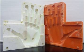
Figure 10. Two-piece mold for the whole hand.
Download figure:
Standard image High-resolution imageThe inner surfaces of the mold were then smoothed carefully using sand paper or rotary (Dremel) tool with wire brush and abrasive buffer attachments. A layer of wax was applied to the inside cavities of the top and bottom parts of the mold. Once dried, a thin layer of release agent was also applied. A wax border was made on the edges of the mold to prevent seepage of silicone from the mold. This seepage would result in void creation in the model. The hand skeleton was then placed in the bottom mold and the steel wires were fed through holes in the mold. The steel wires were then pulled with high tension and clamped to flat and rough surfaces to ensure that the hand skeleton is hanging in the air between the top and bottom molds so that the silicone can properly surround it from all sides. Several more clamps were placed around the edges of the mold, as shown in figure 11, to hold it together tightly and prevent silicone from leaking out. The silicone mixture was then poured into the holes of the mold (check figure 11), one at a time, slowly and with steady rate using a funnel. Note that EcoflexTM 00-35 has 30-minute pot life and four-hour cure time.

Figure 11. Mold is properly clamped, and silicone is poured in all holes.
Download figure:
Standard image High-resolution imageWhen silicone is completely cured, the hand is to be removed carefully from the mold (see figure 12). Any voids or defects can be repaired using the fast setting EcoFlexTM 00-35.
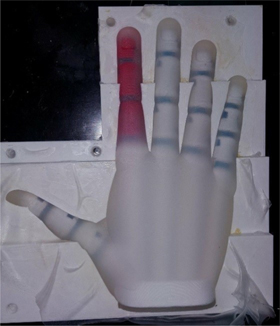
Figure 12. Cured hand in the bottom mold.
Download figure:
Standard image High-resolution imageThe forearm components were also 3D printed and assembled as in figure 4. The palm was connected to the wrist attachment and the forearm central plate using screws whose nuts are placed in cavities in the palm structure, as shown in figure 9(B). The SMA wires were then looped around the two spools as mentioned earlier (check figure 5) and screwed to the terminal block at the end of the forearm central plate. Crimps were then used to connect the SMA wires to the steel wires coming out of the palm. The fan was then installed in its seat in the forearm outer shell. All electric wirings were then connected and both outer shells were assembled to the forearm central plate to complete the assembly. The overall weight of the arm, designed for an average male size, without the battery, was 589 g. Future work will focus on reducing the thickness of the silicone flesh around the hand and perform further optimization studies to reduce the overall weight.
The whole assembled model of MataPro-1 is in figure 13 shaking hands with a person. A video of this test is available online at stacks.iop.org/ERX/2/035041/mmedia. Notice that the person in the middle figure is squeezing MataPro-1 model, which was as flexible as a real human hand would be. When MataPro-1 was actuated with a 'Grip' command, it was powerful enough to overcome the person's squeezing force and hold it properly the same way a human hand would do. During testing, a power supply was used, but a rechargeable Lectron Pro LiPo battery that supplies 11.1 Volts (5200 mAh) can be used instead. The weight of this battery is 350 g, and its dimensions are 13.3 × 4.2 × 2.7 cm, so it can be placed in a small backpack to be carried by the user. SMA-based devices, such as this proposed model, would highly benefit from advancement in Li-ion battery technology that reduces the size and weight of such batteries.
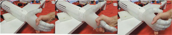
Figure 13. Fully assembled MataPro-1 shaking hands with a person.
Download figure:
Standard image High-resolution image5. Control
The proposed MataPro-1 prosthetic arm offers two non-invasive options for control. The first uses a custom-made application to allow modern, commercially available voice recognition software to fully control the prosthesis, while the second uses Insight Brainwear® (EMOTIV, USA), which is an electroencephalogram (EEG) headset that monitors brainwaves and facial expressions. Both devices interface with the MataPro-1 via a custom-built circuit that ensures 4 amps of current applied to the respective SMA wires in a sequence of electric pulses. Figure 14 shows a simplified schematic of the control circuit flow diagram. Any input signal from the two controllers (EMOTIV Insight headset or the voice recognition phone App) will be sent to the ARDUINO UNO microprocessor that will activate the grip that corresponds to the input signal. The ARDUINO activates the circuit that sends 4 Amp pulses of current to the SMA wires corresponding to the required grip. Five-volt relays (ISO 9002), which acted as switches, were used to control the pulse time accurately without losing voltage. Operational amplifiers (OPA549) were used to ensure the current applied to the SMA wires is non-fluctuating. Upon testing, a pulse time of two seconds was selected at 50% duty cycle. A pulse width modulated (PWM) fan was used, rather than an on/off fan, so that the cubic feet per minute (CFM) and sound intensity could be optimized based on the need of the SMA wires. The selected fan was ultra-speed dual-ball bearing PWM fan, with airflow ranging between 10 to 30 CFM, and noise level between 20 to 42 dBA. This fan requires 12 volts to operate, hence a buck converter was used to reduce the 24 volts supplied from the power source used in testing to 12 volts being applied to the fan. Simone et al [25] used a pulse width modulated (PWM) voltage controller to prescribe a command power to SMA wires. They preferred power control to current/voltage control, because the power affects the equation governing SMA temperature evolution proportionally, while current/voltage enter in the same equation in a nonlinear way. A similar system would be used in future work, but for the sake of testing this proposed design, the aforementioned control system was good enough. If a locking mechanism is introduced to the system as was mentioned earlier, only an initial pulse will be required to actuate the fingers, and then the locking mechanism will lock them in place until a new command triggers the mechanism.

Figure 14. Simplified schematic of the control circuit.
Download figure:
Standard image High-resolution imageThe phone app used Google's speech recognition software to send commands over Bluetooth. Available grips were 'Grip' (all five fingers rotate), 'Tripod' (thumb, index and middle fingers only rotate), 'Pinch' (thumb and index only) and 'Relax' (relax all fingers). The ARDUINO received these commands as numbers, via an HC-05 Bluetooth shield. Using this App, nearly 100% command success was achieved with any user's voice and required no training prior to use. The phone app was designed using MIT APPInventor 2 for Android operating system.
Emokey, a program designed for the EMOTIV Insight headset, was used to convert the facial and mental commands to numbers, which are sent to the ARDUINO. After training one of the authors for about ten hours, the success rate of the different mental commands was between 60% and 70%, while that of the facial expressions ranged between 40% and 100%. It should be noted that control using facial expressions is easier than using mental thoughts and was found to be less affected by external distractions. However, care should be given during the selection of facial expressions for each command, because some facial expressions have similar eye and eyebrow movements, so they might not be interpreted correctly.
6. Testing
6.1. Fingertip force testing
An experimental setup, shown in figure 15, was built to measure the amount of force generated at the fingertip of each finger of MataPro-1. The setup resembles the one used in [24]. The maximum force that could be generated by individual fingers in the proposed design ranged from 7.5 and 7.8 N for the pinky and middle fingers, respectively (since both are actuated using a single SMA wire) to 23.7 N for the thumb as shown in figure 16.

Figure 15. Experimental setup to measure fingertip force.
Download figure:
Standard image High-resolution image
Figure 16. Force produced by each finger.
Download figure:
Standard image High-resolution imageThe total overall applied force is 71.8 N. The measured fingertip forces decrease as the fingers rotate. Most activities of daily living (ADLs) require low grip force. However, tasks that require high grip force and low speeds occur often enough that a prosthetic hand must enable the user to perform such tasks. The grip force exerted by a hand on an object is largely a function of the hand posture, object geometry, and transmission method. Prosthetic hands exhibit different grasp forces depending on the size of the object. The necessary grasp force to maintain an object within a particular grasp is also difficult to predict because it is largely dependent on the friction between the fingers of the hand and the object, the number of contact points, the relative locations of contact, and the object geometry and mass properties [3]. In a precision grasp, the human hand can exert an average of 95.6 N of force [34]. In power grasps, the forces can reach up to 400 N [34]. According to Heckathorne [35], a grip force of only 68 N is required to carry out ADLs. Vinet et al [36] suggested a minimum grip force of 45 N for prosthetic hands for practical use. However, many prosthetic hand designs reported in the literature had grip forces less than 20 N [3]. Although grip force of the proposed design is less than the maximum human grip force, it is enough to grip many daily objects as will be presented in the next subsection.
6.2. Gripping test
Finger angular rotations were measured from pictures taken at full actuation of the proposed model. The five fingers were able to achieve angles of 64°–75° for the MCP joint, 52°–60° for the PIP joint, and 51°–59° for the DIP joint. These angles are close to the average angles made by human hand in daily life. When fully actuated, the fingers do not come to full contact with the palm. Figure 17 shows MataPro-1 gripping different objects of different shapes, sizes and weights using 'grip', 'tripod' and 'pinch' grip patterns. The objects that were tested are water bottle filled with water, orange, staple remover, Styrofoam cup, metallic water bottle, 3D printed airfoil rib, putty knife, tape, alcohol container, metallic plier, cell phone, calculator, compass, vacuum cleaner crevice nozzle attachment, and a spray bottle. Actuation took a fraction of a second, and retraction took 4–5 seconds with the fan operating at maximum power to accelerate the SMA cooling process. The restoring force, enabled by the flexible joints and silicone flesh, also contributed to this relatively small retraction time.

Figure 17. MataPro-1 gripping different objects.
Download figure:
Standard image High-resolution image
7. Summary and conclusions
This paper presented a first concept of a biomimetic prosthetic arm design, called MataPro-1, that uses shape memory alloy muscle wires spooled in the forearm space and cooled during the finger restoration process using a fan. The SMA wires are not routed through the fingers but are connected to steel wires that extends through the finger phalanges. The finger and palm bone structures are 3D printed of PLA while the elastic joints that connect the phalanges are 3D printed of TPU. The whole hand skeleton is covered by silicone flesh to protect the internal components, improve gripping abilities, provide restoring force and make the hand look like a human hand. Control of MataPro-1was achieved using voice recognition phone App or EEG headset that was trained to identify specific mental commands or facial expressions. This dual control system ensures better functionality, reliability and comfort compared to traditional myoelectric controllers. The paper detailed all aspects of the design and manufacturing. Testing proved that the proposed MataPro-1 prosthetic arm design can apply a grip strength comparable to that applied by a human when picking up different household objects.
Future work will focus on customizing the design to different sizes (male and female), reducing the overall weight and power of the design, studying the effects of all geometric and material properties of the skin and elastic joints on the finger stiffness, rotation and restoring force and time. Future work will also improve the testing setup, so that finger rotation and force can be measured, along with SMA wire temperature and applied current, throughout the grasping action. A locking mechanism will also be introduced to lock the fingers at any grip configuration without the need to supply electric current to SMA wires, thus saving energy.
Acknowledgments
This work was conducted as part of the research-based 'Smart Prosthetics' senior design project founded by the first author. The support of the Mechanical Engineering Department, the Instructionally Related Activities (IRA) grant, and the Student Travel and Academic Research (STAR) grant at California State University, Northridge (CSUN) are acknowledged. The following members are also acknowledged: Timothy J. Alejandro, Laura-Ashley Maeda, Cindy Saldana, Brian Richter, Ayden Hairabedian, Emily Molen, Jennifer Fernandez, Utsavkumar Swami, Abdullah Baig, Sean Houston and Chelsey Fryer.
Supplementary data 1 Ring and Pinky_No_Fan-1.
Supplementary data 2 Shake hands with a Smart Prosthetic-1.