
Abstract
Amid the growing interest in triboelectric nanogenerators (TENGs) as novel energy-harvesting devices, several studies have focused on direct current (DC) TENGs to generate a stable DC output for operating electronic devices. However, owing to the working mechanisms of conventional DC TENGs, generating a stable DC output from reciprocating motion remains a challenge. Accordingly, we propose a bidirectional rotating DC TENG (BiR-TENG), which can generate DC outputs, regardless of the direction of rotation, from reciprocating motions. The distinct design of the BiR-TENG enables the mechanical rectification of the alternating current output into a rotational-direction-dependent DC output. Furthermore, it allows the conversion of the rotational-direction-dependent DC output into a unidirectional DC output by adapting the configurations depending on the rotational direction. Owing to these tailored design strategies and subsequent optimizations, the BiR-TENG could generate an effective unidirectional DC output. Applications of the BiR-TENG for the reciprocating motions of swinging doors and waves were demonstrated by harnessing this output. This study demonstrates the potential of the BiR-TENG design strategy as an effective and versatile solution for energy harvesting from reciprocating motions, highlighting the suitability of DC outputs as an energy source for electronic devices.
Highlights
A mechanical rectification based direct-current triboelectric nanogenerator is developed.
The system can generate a unidirectional output regardless of direction of rotation.
A self-adaptive mechanical design is implemented.
Applications for harvesting abundant ambient reciprocating motion are introduced.
Export citation and abstract BibTeX RIS

Original content from this work may be used under the terms of the Creative Commons Attribution 4.0 license. Any further distribution of this work must maintain attribution to the author(s) and the title of the work, journal citation and DOI.
1. Introduction
Owing to increasing environmental pollution and looming energy crises resulting from rapid industrialization and urban development, the demand for energy-harvesting systems capable of harvesting discarded mechanical energy has increased significantly [1–3]. Among such devices, triboelectric nanogenerators (TENGs), which are innovative energy-harvesting devices capable of effectively harvesting subtle movements, have garnered significant attention [4–7]. TENGs, which are founded on the principles of contact electrification and electrostatic induction, offer various advantages, such as design flexibility, diverse material options, simplicity, and cost-effectiveness [8–12]. Leveraging these advantages, TENGs have been developed to harvest various forms of mechanical energy [13–22]. Particularly, as TENGs have the advantage of versatile designs tailored to the mechanical characteristics of ambient energy sources, they have significant potential for harvesting energy from diverse forms of reciprocating motions, such as biomechanical movements, vibrations, and waves [19, 20, 22–24].
However, conventional TENGs inherently produce an alternating current (AC) output according to the periodic physical contact and separation between two dissimilar materials [25–35]. This necessitates a rectification process to transform the AC output into a direct current (DC) for practical electrical use, considering that most electric devices use a DC input [36]. While AC output rectification commonly employs an electrical rectifier composed of diodes, these rectifiers have been reported to increase system complexity and contribute to power losses [37–40]. To mitigate these issues, some studies on DC TENGs that use a mechanical rectification mechanism instead of an electrical mechanism have been reported, emphasizing the mechanical design of the system [41–43]. However, mechanical rectifiers generally encounter difficulty maintaining the DC output upon a change in the rotational direction, primarily because the polarities of the DC outputs of most DC TENGs with mechanical rectifiers are switched during reverse rotation. Thus, DC TENGs that generate a consistent unidirectional DC output regardless of the rotational direction of the rotor are urgently required to ensure effective energy harvesting for the operation of electrical devices.
In this paper, we propose a bidirectional rotating DC TENG (BiR-TENG) that can generate a unidirectional DC output even from reciprocating motion energies, based on its mechanically intelligent design. This design strategy is intended for two salient mechanisms: the mechanical rectification of the AC output and the mechanical switching of the system configuration. A mechanical rectification mechanism that rectifies the AC output was realized by incorporating an electrical brush into the rotational TENG system. However, structures that include an electrical brush are subject to the limitation that the polarity of the rectified DC output reverses with the direction of rotation. Consequently, we introduced a self-adaptable system design based on a mechanical switching mechanism that automatically adjusts the system configuration depending on the direction of rotation.
We also performed system optimization to enhance the performances of both mechanical rectification and mechanical switching. To enhance the synchronization of the rectification process, we meticulously refined the design of the films, which are essential contact materials for contact electrification. Furthermore, to minimize the waste of rotational energy during each direction reversal, we optimized the design of the slot, which is crucial for mechanical switching. In addition, the applicability of the BiR-TENG was demonstrated by its ability to power emergency alarm systems and thermohygrometers, harvesting the movement of swinging doors and the swash and backwash on seashores, thus eliminating the need for external power sources.
The outcomes of our study provide a new perspective on energy harvesting and present a feasible solution for capturing energy from low-frequency, high-amplitude reciprocating motions that are prevalent but largely untapped. This study is also expected to serve as a cornerstone in the realm of innovative energy-harvesting devices and pave the way for the broader application and commercialization of the TENG technology.
2. Result and discussion
2.1. Design and fabrication of BiR-TENG
Figure 1(a) shows the overall configuration of the BiR-TENG. The components of the BiR-TENG can be divided into three parts based on their structural classification: inner rotator, outer rotator, and stator, as shown in figure 1(b). The rotator is divided into inner and outer rotators, with a special design for adjusting the configuration immediately after a change in the direction of rotation. The inner rotator, including the rotational shaft, operates within the outer rotator and shares the same axis of rotation with the outer rotator and stator. The inner rotator has two power transmission rods on the side surface, each engaged with slanted slots on the outer rotator. The outer rotator is designed as a hollow cylinder with two interdigital aluminum plates on its outer surface, which serve as electrodes. The rotation of the outer rotator is driven by torque from the power transmission rods. The stator, the outermost part, supports the rotation of the shaft without axial movement. The stator is also designed as a hollow cylinder with several fluorinated ethylene propylene (FEP) films on the inner surface at regular intervals, with both ends sealed. In addition, for mechanical rectification, two pairs of aluminum electrical brushes are positioned at the top and bottom of the stator on the inner side. These brushes are held in close contact with the electrodes on the outer rotator owing to the elasticity of the spring in each electrical brush module.
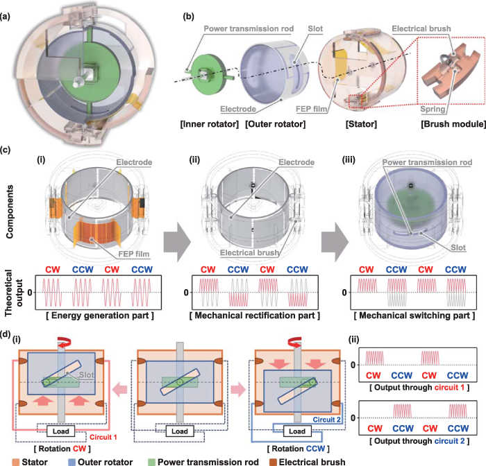
Figure 1. Schematic and theoretical output behavior of the BiR-TENG. (a) Partial cross-sectional schematic of the overall assembly. (b) Components classified by structure. (c) Components classified by function and their corresponding theoretical outputs: (i) energy generation part, (ii) mechanical rectification part, and (iii) mechanical switching part. (d) Mechanical switching mechanism: (i) schematics of configuration depending on rotational direction. (ii) Resultant theoretical output.
Download figure:
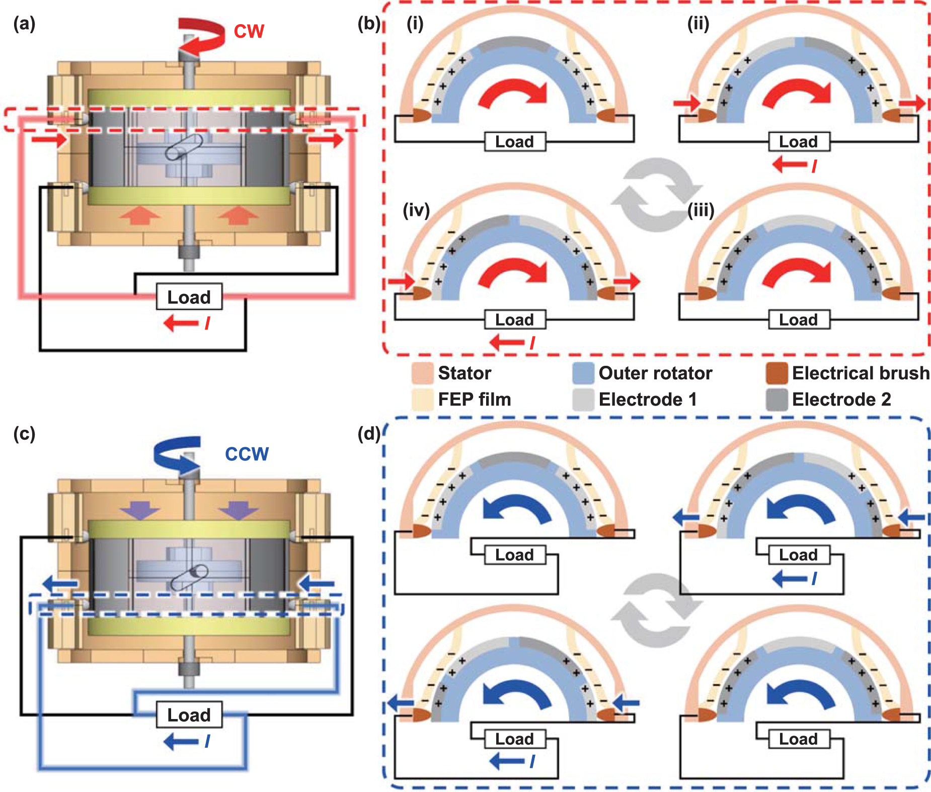
Standard image High-resolution imageBeyond their structural classification, the BiR-TENG components have specific functional classifications, such as energy generation, mechanical rectification, and mechanical switching parts, as shown in figure 1(c). First, the energy generation part shown in figure 1(c-i), which includes the electrodes of the outer rotator and the FEP films of the stator, directly participates in energy generation. The rotation of the outer rotator leads to continuous friction between the FEP films and the electrodes. Therefore, the mechanical energy is converted into electrical energy via contact electrification and electrostatic induction. This process, which is common in most rotational TENGs, generates an AC output. The mechanical rectification part in figure 1(c-ii), including the electrodes of the outer rotator and the electrical brushes of the stator, rectifies the output current through the mechanical rectification mechanism. This part is designed to shift the electrical brush to the other electrode repeatedly when the current direction changes, considering the phase of the produced AC output. Consequently, the AC output is rectified to the DC output. This rectification mechanism is typical of several conventional TENGs that employ mechanical rectification [41, 42]. However, challenges arise when the direction of rotation changes. The DC output polarity also changes because of the system configuration, resulting in a rotation-dependent DC output. Therefore, to ensure that the unidirectional DC output is independent of the rotational direction, a mechanical switching part was integrated into this study. The mechanical switching part in figure 1(c-iii), including the slots of the outer rotator and the power transmission rods of the inner rotator, allows the system to adjust its configuration based on the rotational direction of the shaft without external manipulation. Therefore, when the rotational direction changes, the pair of electrical brushes responsible for the current flow is replaced with another pair connected to a different pair of electric wires. Owing to the combination of mechanical configuration adaptation and a specially designed circuit, the incomplete DC output, which is dependent on the rotational direction, can be completely rectified into a unidirectional DC output irrespective of the rotational direction. This switching is feasible because the position of the outer rotator is adjusted according to the rotational direction by the interaction between the slot and the power transmission rod, as shown in figure 1(d-i). After a reversal in the rotational direction of the shaft, the transmission rod does not immediately induce rotation in the outer rotator but instead slides along the path of the slot. The rotational energy is fully utilized to rotate the outer rotator only after the transmission rod reaches the slot end. Consequently, the slant in the slot causes the unanchored outer rotator to move axially. Thus, when the shaft rotates clockwise, the outer rotator moves upward along the shaft before its rotation, allowing the forward DC output to flow through the upper brush pair. Conversely, during the counterclockwise shaft rotation, the outer rotator descends, directing the reversed DC output through the lower brush pair. Each brush pair is connected to separate circuits, and each circuit is attached to the load in opposing directions. Therefore, the reversed DC output generated during counterclockwise rotation flows through the lower brush pair, which connects in the opposite direction to the load, ensuring that the load only receives a forward DC output. Consequently, as shown in figure 1(d-ii), during clockwise rotation, the forward DC output flows through Circuit 1, whereas during counterclockwise rotation, it flows through Circuit 2. Thus, by altering the circuit according to the current direction, our system ensures that only the forward current reaches the load. This self-adaptive mechanical switching operates autonomously, allowing the BiR-TENG to adjust based on the rotational direction of the shaft, resulting in consistent unidirectional DC energy generation.
2.2. Working mechanism of energy generation
Figure 2 shows the detailed working mechanism for producing the electricity output. Given that the BiR-TENG harvests electrical energy via distinct circuits contingent on the rotational direction, the operating mechanism is explained for each direction. Figure 2(a) shows the system configuration and current flow during clockwise shaft rotation. Under these conditions, current flows through the upper electrical brush pair. The current direction is delineated in stages, as shown in figure 2(b). Considering their triboelectric characteristics, FEP films, which are known for their high electron affinity, are affixed to the inner surface of the stator [44]. These FEP films are in contact with the aluminum electrodes. As the rotator rotates, the FEP films accumulate a substantial negative charge through contact electrification with the electrode (figure 2(b-i)). As the rotation continues, the contact area with the FEP film gradually shifts from electrode 1 to electrode 2 (figure 2(b-ii)). Throughout this transition, the induced positive charges on electrode 1 are transferred to electrode 2, consequently generating a current in the direction illustrated in the schematic. When the contact area between the FEP film and electrode 2 is maximized, the induced positive charge on the surface of electrode 2 is also maximized (figure 2(b-iii)). Subsequently, as the FEP film shifts from electrode 2 to electrode 1, positive charges are transferred from electrode 2 to electrode 1 (figure 2(b-iv)). Even at this step, a current is produced in the same direction as that shown in figure 2(b-ii). Thus, by alternating the contacts between the electrical brushes and the electrodes in response to the current flow, a current in a consistent direction can be generated during rotation. Similarly, figure 2(c) shows the configuration and current flow when the shaft is rotated counterclockwise. Under these conditions, a lower electrical brush pair is used for current flow. Figure 2(d) shows the working mechanism, demonstrating the current flowing through the lower electrical brush. Although counterclockwise rotation employs a working mechanism analogous to that in the clockwise direction, the direction of the current at the electrical brush is the opposite. However, by establishing an inverse connection between the electrical brush and the load, the current direction at the load remains consistent, matching the clockwise rotation condition. Thus, the innovative system and circuitry design of the BiR-TENG ensure the derivation of a unidirectional DC output regardless of the bidirectional rotation.
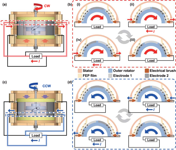
Figure 2. Working mechanism of the BiR-TENG. (a) Schematic of the system configuration in a clockwise rotation. (b) Schematics of the working mechanism in a clockwise rotation. (c) Schematic of the system configuration in a counterclockwise rotation. (d) Schematics of the working mechanism in a counterclockwise rotation.
Download figure:
Standard image High-resolution image2.3. System design optimization
For a unidirectional DC output, we emphasized two primary areas of optimization: optimizing the film attachment to eliminate the reverse current during the mechanical rectification phase and refining the slot shape for potent output generation during the mechanical switching process. Initially, we delineated the process of film attachment optimization using figures 3(a)–(f). The mechanical rectification phase involves the shifting of the electrical brush to another electrode when the output current reaches zero. Therefore, it is imperative to synchronize the output behavior with the shift in the electrical brush. However, the flexible nature of the FEP film makes it susceptible to deformation owing to friction, potentially disrupting the synchronization. In particular, the drag arising from friction against the opposing material is prevalent in film-based TENGs. Although a TENG system designed to harness unidirectional rotation can address this issue by simply adjusting the position of the electrical brush, the BiR-TENG requires synchronization in both directions of rotation. Hence, we adopted a strategy to minimize film deformation.
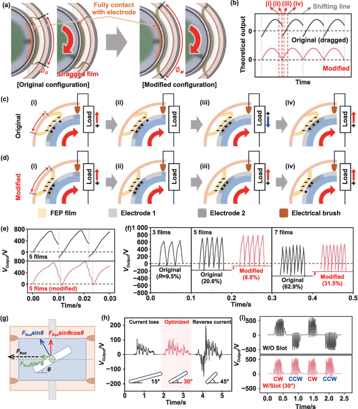
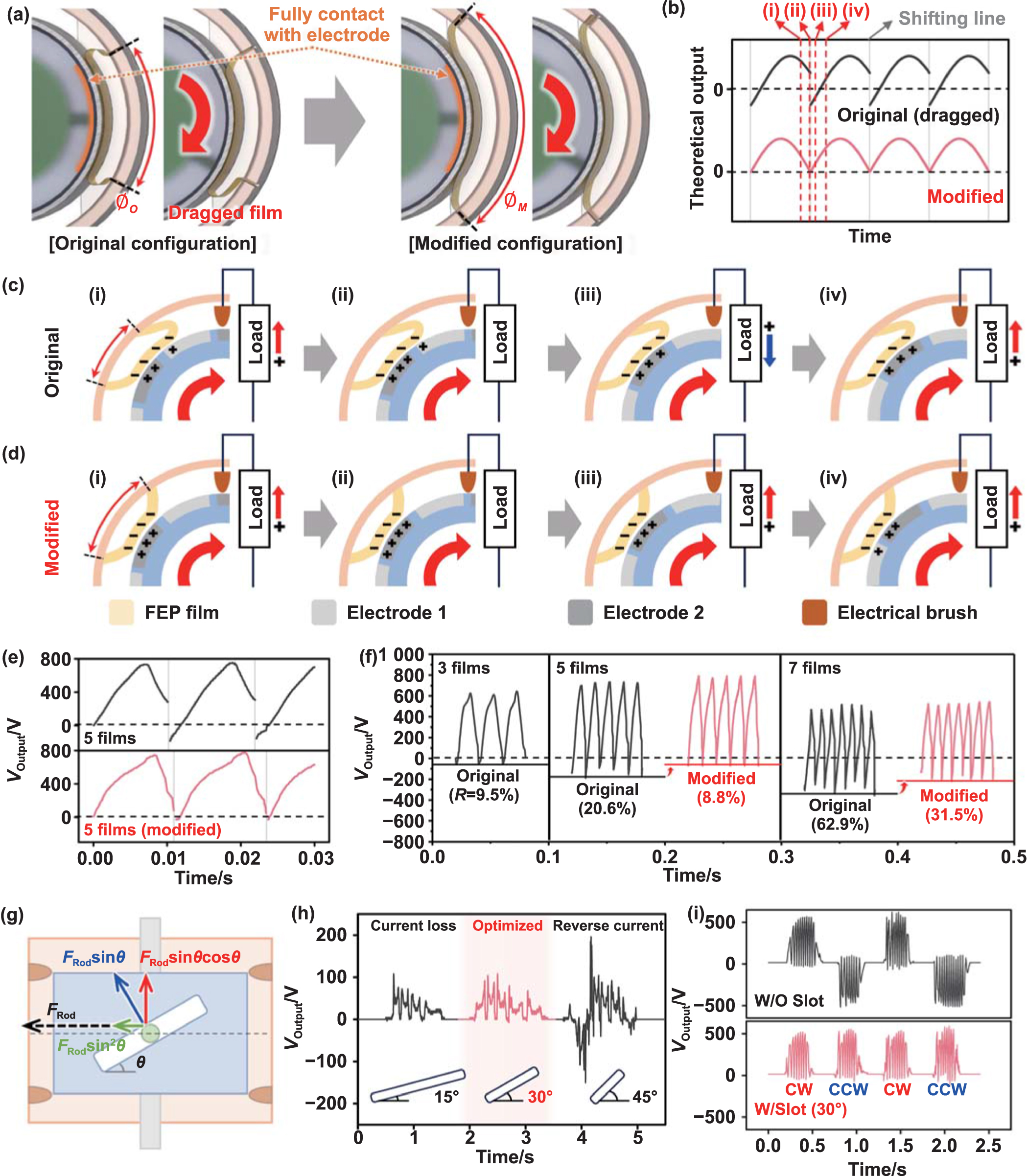
Figure 3. System optimizations to improve (a)–(f) mechanical rectification and (g)–(i) mechanical switching. (a) Schematics of the FEP film shape in the original and modified configurations. (b) Resultant theoretical output. Schematics of the working mechanism (c) in the original configuration and (d) in the modified configuration. (e) Experimental output voltages in both configurations. (f) Output voltages in both configurations with three, five, and seven films at 500 rpm. (g) Free-body diagram of the interaction between the power transmission rod and the outer rotator. (h) Output voltages during a half rotation with various angles of the slot. (i) Resultant output of the optimized BiR-TENG.
Download figure:
Standard image High-resolution imageFigure 3(a) shows a schematic comparison of the original and modified configurations. To maximize the output generated by electrostatic induction, the FEP film is designed to be in full contact with the electrode in both configurations. In the original configuration, given uniformly spaced supports for attaching each end of the FEP film, the angle between the ends of a single FEP film ( ) is relatively narrow. Consequently, loose FEP films are predisposed to dragging owing to friction. In addition, the drag of the film delays the output behavior, causing a shift in the electrical brush before the output reaches zero. This misalignment results in a reversed output immediately after the shifting line, as shown in the theoretical output graph in figure 3(b). For better comprehension, figure 3(c) shows the schematics of charge movements in the original configuration of each step in the shifting phase, as shown in figure 3(d). During the sliding of the FEP film from electrode 1 to electrode 2, a forward current flows through the load (Step i). However, before the FEP film fully covers electrode 2, the electrical brush shifts from electrode 2 to electrode 1, thus reversing the charge flow (Step ii). Consequently, a reverse current is produced until the FEP film moves completely to electrode 2 (Step iii). Subsequently, as the FEP film slides from electrode 2 to electrode 1, a forward current is generated (Step iv).
By contrast, in the modified configuration, an increased angle between the ends of a single film ( ) minimizes the drag of the FEP film. This ensures that no reverse current occurs during the shifting process (figures 3(b) and (d)). Consequently, the actual output voltage (VOutput) graph, as shown in figure 3(e), shows that the reverse voltage evident in the original configuration with five films is considerably reduced in the modified configuration. Figure 3(f) shows the VOutput for both configurations depending on the number of FEP films at 500 rpm. As the electrical brushes can face each other only when the number of films is odd, we set the film counts to three, five, and seven. To evaluate the effectiveness of system modifications, we introduce the reverse voltage ratio (R) as follows:

where VMin and VMax are the peak values of the reverse and forward voltages, respectively. Therefore, a lower R value indicates better synchronization between the output behavior and the shifting of the electrical brush. To determine the optimal system, we compared VMax and R for each condition. Considering that the values of VMax are 643 V, 756 V, and 540 V for the systems with three, five, and seven films, respectively, the system with five films is superior. The VMax of the system with five films was higher than that of the system with three films because of the increased movement of charges within the same duration owing to the increased frequency. Conversely, the reduced output in the system with seven films is thought to be due to film deformation, because the sum of the contact area decreases as the electrodes and FEP films become more segmented. Furthermore, with an R of 8.8%, the modified configuration with five films demonstrates efficient rectification. The system with seven films struggles to mitigate film deformation significantly owing to limitations in the increase in  caused by structural constraints. There is still room to reduce the R value, and future studies can further optimize it by enhancing system stability during high-speed rotations. The VMax and R values for each configuration are plotted in figure S1. For a more quantitative comparison of the output results, transferred charges (Q) in modified systems with five and seven films each at a rotational speed of 500 rpm are measured as shown in figure S2. Based on these findings, we chose a modified configuration with five films as the optimal system for the subsequent experiments. The strategy of minimizing the film deformation represents a universal optimization procedure that can be applied to most DC TENGs employing mechanical rectification, where the precise timing of rectification is imperative. Beyond the adjustments of film attachment positions proposed in this study, it is anticipated that film deformation can be reduced through various methods, including the modulation of film thickness, the alteration of film attachment angles, and the adjustment of the diameter of the rotator or stator.
Figures 3(g) and (h) show the optimization of the slot design, which plays a pivotal role in mechanical switching. Figure 3(g) illustrates a free-body diagram detailing the interaction between the power transmission rod and the outer rotator during the mechanical switching process. With the slot slanted at a specific angle ( ), owing to the force in the rotational direction of the power transmission rod (
 ), a force perpendicular to the slot (
 ) is applied on the outer rotator. Consequently, owing to the axial component (
 ) of this force, the outer rotator experiences axial movement while the power transmission rod reaches the end of the slot. Hence, precision in setting
  for this mechanical switching process is crucial. An excessively small
  necessitates a longer slot to allow the outer rotator sufficient movement, which indicates that a significant portion of the rotation of the inner rotator is consumed in the switching process, causing a delayed onset of the rotation of the outer rotator. In contrast, an excessively large
  magnifies the rotational force on the outer rotator (
 ) during the mechanical switching process. This results in the rotation of the outer rotator before the switch is completed, leading to the generation of a reverse current. Figure 3(h) shows the VOutput during a half rotation (180°) following the direction reversal of the shaft in systems with a
  of 15°, 30°, and 45°. Given that the system incorporates five films, an ideal scenario yields five output cycles. In the case of
  = 15°, the elongated slot wasted the rotation of the inner rotator, resulting in four output cycles, which indicates a loss in current generation. At
  = 45°, the rotation of the outer rotator immediately after the direction reversal of the shaft caused a reverse current. However, at
  = 30°, five output cycles were achieved without the emergence of a reverse current. In addition, we directly compared the output results at each
  depending on the rotation speed to confirm the influence of the rotation speed on the tendency of the output. Consequently, although the magnitude of the output voltage increased with increasing rotational speed, it still generated four output cycles at 15° and a reverse current at 45°, as shown in figure S3. Therefore, the BiR-TENG adopts a
  of 30° to minimize the rotational energy dissipation and ensure the generation of a unidirectional DC output. Consequently, it can be observed that the mechanical switching is conducted by consuming minimal rotation of the inner rotator, as shown in supporting video 1. In addition, following the collision between the transmission rod and slot, the rotation of the outer rotator proceeds naturally. Through these optimization processes, the BiR-TENG was equipped to reliably generate a unidirectional DC output from reciprocating movements, as illustrated in figure 3(i). The results are noteworthy in that they demonstrate that only through the mechanical design of the system can the limitations of an electrical rectifier be overcome, achieving the effective rectification of the AC output. In addition, the simplicity of the slot structure suggests its straightforward application in other rotational TENG systems.
2.4. Output performances
Figure 4 shows the output performance of the BiR-TENG with an optimized configuration that employs five FEP films and a 30° slot. Specifically, figures 4(a)–(c) illustrate the VOutput, output current (IOutput), and Q of the BiR-TENG at the rotation speeds of 100 rpm, 300 rpm, 500 rpm, and 700 rpm. VOutput exhibited a saturation trend as the rotation speed increased, reaching 850 V at 700 rpm. Furthermore, IOutput increased depending on the rotation speed, peaking at 11.8 μA at 700 rpm. Accordingly, as shown in figure 4(c), Q demonstrated a value of 2.17 μC over a duration of 0.3 s at 700 rpm. As the rotation speeds increase, the IOutput continues to rise, but the VOutput exhibits convergence at a certain value. This tendency can be explained through the intrinsic characteristics of the generation principle of the TENG. TENG makes current through the movement of induced charges, which are induced by triboelectric charges from contact between the contact materials. In addition, once the system configuration is determined, the maximum amount of charge generated by the contact is also established. Consequently, there exists a theoretical limit to the output voltage, which can be confirmed by measuring the open-circuit voltage. The open-circuit voltage is a constant value, irrespective of frequency, as evidenced in several TENG studies [4, 42]. In our research, we have indirectly confirmed the open-circuit voltage by demonstrating the output voltage convergence around 880 V, as shown in figure S4. Figure 4(d) shows the relationship between the output power (POutput) and VOutput of the BiR-TENG at the rotation speed of 300 rpm under the influence of an external loading resistance ranging from 100 kΩ to 10 GΩ. POutput is calculated using VOutput as follows:
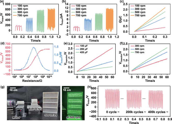
Figure 4. Electrical output performances of the BiR-TENG. Output results at the rotation speeds of 100 rpm, 300 rpm, 500 rpm, and 700 rpm: (a) output voltages, (b) output currents, and (c) transferred charges. (d) Curves of output voltage and power with different loads. Charging performances with varying (e) capacitances and (f) rotation speeds. (g) Photographs of the experimental setup of the BiR-TENG with a motor to light LEDs. (h) Long-term output result of the BiR-TENG.
Download figure:
Standard image High-resolution imagewhere R denotes the external loading resistance. At an external resistance of 100 kΩ, VOutput approached zero. As the resistance increased, VOutput correspondingly increased and eventually saturated at 560 V at 10 GΩ. Based on calculations using equation (2), the maximum POutput of 1.48 μW was achieved at an external resistance of 50 MΩ. Furthermore, to evaluate the electric energy output performance comprehensively, the BiR-TENG was employed to charge capacitors with varying capacitances at a rotation speed of 300 rpm, as shown in figure 4(e). The voltages across the capacitor (VCapacitor) reached the values of 2.57 V, 1.15 V, and 0.56 V within a minute for the capacitances of 100 μF, 200 μF, and 420 μF, respectively. Additionally, the charging results of a 200 μF capacitor over the duration of a minute, with varying rotation speeds, are shown in figure 4(f). The BiR-TENG, under an effective DC output at 500 rpm, could brightly illuminate 500 LEDs connected in series, as shown in figure 4(g). Figure 4(h) shows the VOutput of the BiR-TENG during long-term operation at 500 rpm. Owing to the film-type design that ensures minimal wear, the BiR-TENG retained approximately 95% of its output even after 400k cycles, indicating remarkable durability, as shown in figure 4(h).
2.5. Applications
The BiR-TENG can harvest reciprocating energy to charge energy storage devices owing to its stable unidirectional DC output. Furthermore, it can directly power electronic devices without requiring electrical rectifiers. In this section, we verify the applicability of the BiR-TENG by harvesting reciprocating energy sources commonly found in the surroundings and powering electronic devices.
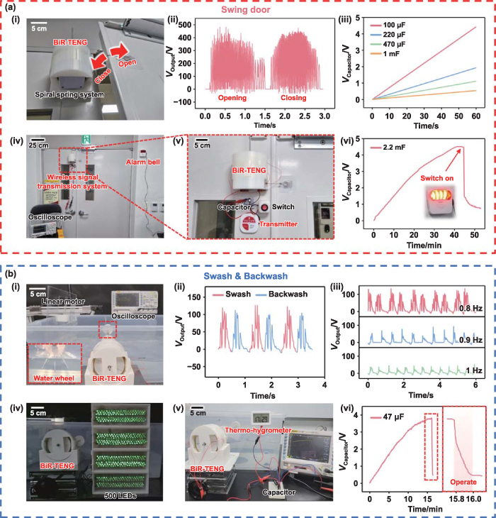
Figure 5(a) shows an application that harvests the mechanical energy of swing doors, which are ubiquitous fixtures in most buildings. As shown in figure 5(a-i), a spiral spring system, where a wire is wound around its shaft, is integrated with the BiR-TENG, sharing their shaft. The integrated system and the end of the wire are attached to the left and right swing doors, respectively. Thus, when the swing door is opened, the wire is pulled, unwinding the wire and causing the shaft to rotate numerous times in a clockwise direction. Subsequently, when the swing door is closed, the restoring force of the spiral spring induces an equal number of rotations in the counterclockwise direction. Through this mechanism, each opening and closing of the door allows the BiR-TENG to generate approximately 70 peaks of DC output ranging from 300 V to 400 V, as illustrated in figure 5(a-ii). Owing to the DC output, which is suitable for energy storage, the BiR-TENG can effectively charge capacitors of varying capacitances from the swing-door motion, as shown in figure 5(a-iii). Figure 5(a-iv) shows the emergency alarm system built based on the BiR-TENG. The emergency alarm system, which consists of a wireless signal transmission system and an alarm bell, monitors the charging and discharging voltages of the capacitors via a connected oscilloscope. The magnified views in figure 5(a-v) show the wireless signal transmission system, which consists of the BiR-TENG, capacitor, switch, and transmitter. In this configuration, after charging the capacitor by harvesting the motion energy of the swinging door and turning on the switch, the transmitter sends a wireless signal to activate the alarm bell. As demonstrated in figure 5(a-vi), the alarm bell was successfully powered by charging a 2.2 mF capacitor to 4.5 V. A detailed demonstration of the emergency alarm system is provided in supporting video 2.
Figure 5. Applications of the BiR-TENG. (a) Application in the swing door: (i) photograph of the BiR-TENG with a spiral spring system, attached to the swing door. (ii) Output voltages when opening and closing the swing door. (iii) Charging performances with varying capacitances. (iv) and (v) Photograph of the experimental setup for operating a wireless signal transmission system. (vi) Curve of voltage while charging and discharging a capacitor. (b) Application in the swash and backwash: (i) photograph of the BiR-TENG for harvesting swash and backwash motions. (ii) Output voltages from swashes and backwashes. (iii) Output voltages depending on the frequency of the linear motor. (iv) Photograph of LEDs illuminated by harvesting swash and backwash motions. (v) Photograph of the experimental setup for operating a thermohygrometer. (vi) Curve of voltage while charging and discharging the capacitor.
Download figure:
Standard image High-resolution image
Figure 5(b) shows the application of the BiR-TENG for harvesting mechanical energy from the commonly observed swash and backwash motions at seashores. As the swash and backwash created when a wave breaks on the seashores travel long distances and occur continuously, they hold significant potential as energy-harvesting sources. Therefore, through the following experimental results, we examined the feasibility of applying the BiR-TENG to the swash and backwash. Figure 5(b-i) and supporting video 3 show the experimental setup used to simulate the motions of the swash and backwash. The setup includes an acrylic plate attached to a linear motor to mimic the pushing and pulling of water within a tank. In addition, a water wheel was coupled to the shaft of the BiR-TENG, converting the motion of the water into reciprocating rotation. Figure 5(b-ii) shows VOutput when generating a 0.8 Hz frequency swash and backwash moving over 15 cm of the acrylic plate. Under these conditions, each swash and backwash produced approximately three cycles of VOutput, each exceeding 50 V. As shown in figure 5(b-iii), a comparison at the frequencies of 0.8 Hz, 0.9 Hz, and 1 Hz reveals the highest VOutput at 0.8 Hz. This indicates that the water wheel rotates at a more significant angle at lower frequencies. While experiments at even lower frequencies were not conducted owing to lab-scale constraints, we anticipate that higher outputs would be generated in real seashore conditions with lower frequencies and longer travel distances of the swash and backwash. Consequently, we illuminated 500 LEDs, as shown in figure 5(b-iv) and in supporting video 4. Moreover, a thermohygrometer was powered using the experimental setup in figure 5(b-v). As shown in figure 5(b-vi) and supporting video 5, a capacitor of 47 μF could be charged to 3.8 V in 15 min, and upon discharging, it could operate the thermohygrometer for 10 s. Consequently, the applicability of the BiR-TENG was demonstrated through its effective conversion of various forms of reciprocating motion energy into DC electrical energy. Additionally, for applications in high-humidity environments such as the seashore, it is necessary to consider the impact of humidity on output. Therefore, figure S5 presents the results of the output voltage under various humidity conditions. The results indicate a sharp decrease in VOutput with increasing humidity. These findings experimentally confirm that, for applications of TENGs in high-humidity environments, packaging to maintain low internal humidity is essential.
3. Conclusion
We designed a BiR-TENG, an innovative system that can produce a unidirectional DC output from a reciprocating motion. Our design strategy focused on mechanical rectification and mechanical switching. Additionally, to enhance the effectiveness of the BiR-TENG, we meticulously optimized the film attachment design for effective mechanical rectification and the slot design for effective mechanical switching. Consequently, the BiR-TENG could effectively harvest energy from the reciprocating movements of swing doors, and swashes and backwashes, demonstrating its practicality by successfully powering devices, including a wireless signal transmission system and thermohygrometer.
The significance of this study lies in its capacity to overcome structural challenges and thereby considerably expand the potential applications of TENGs by generating a stable DC output from reciprocating motions. Furthermore, the ability of the BiR-TENG to harvest energy effectively from common reciprocating energy sources underscores its practical viability as an energy-harvesting device. While the primary aim of this study was to propose a novel mechanical design strategy, future studies could adopt this strategy to develop diverse harvesting systems, further enhancing the applicability and practicality of TENGs. In conclusion, our study is expected to pave the way for the broader applications and commercialization of TENGs, serving as a cornerstone in the realm of innovative energy-harvesting devices.
4. Experimental section
4.1. Fabrication of BiR-TENG
The BiR-TENG (dimensions: 10 cm (diameter) × 7 cm (height)) consisted of three main parts: an inner rotator, an outer rotator, and a stator. The parts were fabricated using a 3D printer (A15CR, CUBICON) with polylactic acid filament. An aluminum shaft (diameter: 4 mm) was fixed to the inner rotator using a lock nut. Interdigitally shaped aluminum plates (thickness: 0.5 mm) were attached to the outside of the outer rotator as electrodes. FEP films (dimensions: 30 mm × 80 mm × 125 µm) were attached inside the stator at regular intervals. The 3D-printed brush module included a spring and a convex aluminum plate.
4.2. Electrical measurement
The output voltage was measured using an oscilloscope (DS1074z, Rigol) connected to a high-voltage probe (DP-50, Pintek). The resistances of the oscilloscope and high-voltage probe were 1 MΩ and 15 MΩ, respectively. A low-noise current preamplifier (SR570, Stanford Research Systems) was used to measure the current and connect to the oscilloscope. A tachometer (GM8905, Benetech Inc.) was also used. All the electrical measurements were conducted at room temperature (25 °C) at a relative humidity of 30%.
4.3. Applications
To harvest the mechanical energy of a swinging door, the BiR-TENG was installed on the swing door and coupled with a commercial wire door. As the wire door was closer, the movement of the swing door was converted into the rotation of the shaft. To simulate artificial swashes and backwashes, an acrylic plate coupled with a linear motor (PSA4510, i-ROBO Co., Ltd) was used in the water tank (dimensions: 70 cm (width) × 40 cm (depth) × 25 cm (height)). The water wheel was fabricated with a 3D-printed body and acrylic plates.
Acknowledgments
This work was supported by the National Research Foundation of Korea (NRF) grant funded by the Korea government (MSIT) (No. 2022R1C1C1008831).
This work was also supported by the Human Resources Development of the Korea Institute of Energy Technology Evaluation and Planning (KETEP) grant funded by the Ministry of Trade, Industry and Energy of Korea (No. RS-2023-00244330).
S J P was supported by Basic Research Program through the National Research Foundation of Korea (NRF) funded by the Ministry of Education (No. 2018R1A6A1A03025526).
Supplementary data (0.4 MB PDF)
Supplementary data (5.5 MB MP4)
Supplementary data (7.7 MB MP4)
Supplementary data (8.4 MB MP4)
Supplementary data (8.9 MB MP4)
Supplementary data (15.3 MB MP4)