
Abstract
The flat plane of small surface roughness below 0.1 µm average roughness was obtained for monocrystalline diamond by nanosecond pulsed laser irradiation of 1060 nm and post-process acid cleaning, at a laser fluence around the material removal threshold value. The glossy and flat plane at the bottom of the micro-groove was parallel to the top surface of the specimen, although the round beam of Gaussian mode was irradiated in the direction perpendicular to the top surface of specimen. The square beam of top-hat mode produced a shallower micro-groove with a wider, flatter bottom compared with the round beam in Gaussian mode. The creation method of the flat plane with small surface roughness was discussed in the arrangement strategy of linear micro-grooving by the square beam of top-hat mode. Normal side-by-side repetition of linear micro-grooving did not create a flat plane with constant depth. Therefore, a two-step scanning method was proposed in order to overcome the problem in the normal side-by-side repetition of liner micro-grooving. Non-removal areas were partly retained between the processing lines in the first step, and the laser scanning was conducted on the retained area in the second step. The newly proposed two-step scanning method was practical and useful to create a widely flat plane with small surface roughness, and the two-step scanning method provided superior control over the micro-groove depth. This proposed method can reduce the surface roughness in addition to the shape creation of monocrystalline diamond, and it can be used as a high-quality micro-shape fabrication method of monocrystalline diamond.
Highlights
The flat plane of small surface roughness below 0.1 µm average roughness was obtained for monocrystalline diamond by nanosecond pulsed laser irradiation of 1060 nm and post-process acid cleaning at a laser fluence around the material removal threshold value.
In the micro-grooving process of monocrystalline diamond, a flat and smooth surface perpendicular to a beam axis was obtained by combining normal nanosecond laser and acid cleaning at a laser fluence around the threshold value of material removal.
Normal repetition of linear micro-grooving side by side could not create a flat plane with a constant depth, but the newly proposed two-step scanning method created a wide, flat plane with low surface roughness.
Export citation and abstract BibTeX RIS

Original content from this work may be used under the terms of the Creative Commons Attribution 3.0 license. Any further distribution of this work must maintain attribution to the author(s) and the title of the work, journal citation and DOI.
1. Introduction
Diamond has been widely used in cutting tools because of its excellent properties, such as high strength and hardness with high thermal conductivity and low thermal expansion [1, 2]. Diamond is not only used in cutting tools, but also as a semiconductor material for high power devices [3, 4]. Diamond has attracted attention for applications that require high-quality micro-shape creation. However, diamond micro-structures are difficult to create due to its high strength and hardness. The mechanical machining method can create diamond micro-structures, but the large tool wear results in long processing times. In recent years, laser beam machining has been used as a processing method for diamond due to highly efficient processing without mechanical contact [5].
Synthetic diamonds are mainly classified into four types (Ia, Ib, IIa, IIb) [6] according to the amount and remaining ratio of impurities, such as nitrogen and boron, and type Ib is widely used for industrial applications. Type Ib has a yellow color and highly transparent in the visible wavelength. The near-infrared laser of 1 μm wavelength has been widely used as a laser source for the processing of diamond, and the transmittance ratio of diamond Ib is approximately 70% around 1 μm wavelength [7]. Although diamond has high optical transparency for near-infrared and visible wavelengths, diamonds can absorb pulsed lasers with high peak power. Normally, the energy of the laser beam is absorbed at defects and/or surface in laser beam processing of diamond, and diamond is removed by the combination of ablation phenomena, graphitization and oxidization [8]. However, in the shape creation process of diamond, several polishing steps are necessary to achieve the required low surface roughness before the finishing process, in which abrasive diamond powder grains are commonly used. It takes quite a long time to finish the polishing processes and requires many polishing steps, which results in high production cost. Therefore, in addition to the shape creation, the surface roughness of the processed area must be reduced to effectively lower, which leads to the reduction of production cost and total processing time of laser beam machining diamonds. Our previous study clarified that a picosecond pulsed laser of 12.5 ps created a flat and smooth plane of monocrystalline diamond at the plane perpendicular to the beam axis, although a round beam of Gaussian mode was used [9]. However, the processing widow to achieve smooth and flat surface was limited. Precise control of the process is necessary because this process is mainly performed by crack propagation. If a similar process to achieve a smooth and flat plane can be performed in the micro-processing of monocrystalline diamond by commonly used nanosecond pulsed laser, a more affordable process with a simple processing setup can be expected for micro-fabrication of monocrystalline diamond.
The removal process of monocrystalline diamond by the nanosecond pulsed laser was also discussed, and some researchers reported that there was smooth surface at the bottom of V-shaped micro-grooves [10, 11]. However, the smooth area is limited to the tip of the micro-groove, and a flat surface could not be obtained for a wide area. The effects of the beam intensity distribution characteristics on the fabrication of smooth surfaces had not been discussed, and the creation method of flat and smooth areas by the combination of linear micro-grooving has not been clarified. It might be possible to obtain a smooth and flat surface in the micro-machining of monocrystalline diamond by nanosecond pulsed laser, but the processing requirements for such a smooth surface have not been sufficiently discussed.
Therefore, a high-quality micro-processing method of monocrystalline diamond was experimentally investigated to obtain a low surface roughness in addition to the shape creation process by the nanosecond pulsed laser. The influence of intensity distribution on removal characteristics was discussed using the round beam of Gaussian mode and the square beam of top-hat mode. Furthermore, the creation method of a flat, wide area through the combination of linear micro-grooving was investigated.
2. Experimental methods
2.1. Laser irradiation method
A nanosecond pulsed laser was used in this experiment, and its pulse duration and wavelength were 200 ns and 1060 nm, respectively. Figure 1 shows two optical setups for two types of laser beams. Figure 1(a) illustrates the setup for the round beam of Gaussian mode, and a circular spot with a diameter of 45 µm was obtained by focusing a laser beam of 10 mm in diameter through a focusing lens of 100 mm focal length. On the other hand, the square beam of top-hat mode was obtained by using an optical fiber with a square core, as shown in figure 1(b). A laser beam of 10 mm in diameter was put into an optical fiber with a 50 µm square core using a focusing lens of 100 mm focal length, and a square spot of 25 µm inside was obtained using a focusing lens of 30 mm focal length. In both optical setups, the surface of the monocrystalline diamond was set 20 µm below the focusing point. For single line processing, the laser irradiation experiments were carried out in air without an assist gas. Only in the case of wide area formation, compressed air was supplied as an assist gas at 90 l min−1 from a nozzle with an inner diameter of 6.5 mm, which was located at the upper side of the scanning line. The angle between the laser axis and nozzle one was set to 60°, and the tip of nozzle was set 10 mm away from the irradiation point.

Figure 1. Schematic diagram of optical setups and intensity distributions at the focusing points of (a) round beam of Gaussian mode and (b) square beam of top-hat mode.
Download figure:
Standard image High-resolution imageTable 1 shows the experimental conditions used in this study. Shot number and laser fluence were varied at a constant pulse repetition rate of 50 kHz. Shot number was defined as the number of laser pulses irradiated within the spot sizes of 45 µm in diameter for round shape and 25 µm in square shape. The shot number defined in this paper corresponds to the overlap rate, as shown in table 2. The overlap rate varied from 97.15% for 35 shots to 99.98% for 5000 shots.
Table 1. Main experimental conditions.
| Beam type | Round beam of Gaussian mode | Square beam of top-hat mode |
|---|---|---|
| Wavelength | 1060 nm | |
| Polarization | Random | |
| Pulse duration | 200 ns | |
| Pulse repetition rate | 50 kHz | |
| Collimation lens | — | f 100 mm |
| Focusing lens | f 100 mm | f 30 mm |
| Spot diameter | 45 µm | 25 µm |
Table 2. Relationship between shot number and overlap rate.
| Shot number | 35 shots | 100 shots | 500 shots | 1000 shots | 2000 shots | 5000 shots |
| Overlap rate | 97.15% | 99.00% | 99.80% | 99.90% | 99.95% | 99.99% |
The surface roughness and the cross-sectional shape of the processed micro-groove were measured by a white light interference microscope, and the processed areas were observed by scanning electron microscope (SEM). After the laser irradiation experiments, the specimens were cleaned in an acid of 60% nitric acid and 98% sulfuric acid with a ratio of 1:3, and the processed specimens were kept in this mixed liquid for 1 h at 300 °C.
2.2. Specimen
The specimen was a type Ib monocrystalline diamond synthesized by the high-pressure high-temperature synthesis method, in which carbon materials are heated to about 1500 °C and pressurized to 5–6 GPa [12]. The specimen was 1.8 mm wide and 0.6 mm thick. The monocrystalline diamond had a crystallographic orientation [13], and the laser beam was irradiated in the direction perpendicular to the (111) plane.
3. Effect of beam intensity distribution on micro-shape fabrication
3.1. Processing characteristics by round beam of Gaussian mode
The characteristics of the linear micro-grooving process were investigated using the round beam of Gaussian mode. The linear micro-grooving experiment by the round beam of Gaussian was conducted at 3.1 J cm−2 laser fluence and a shot number of 1000 (99.90% overlap rate), and the laser irradiation from the right to left stopped instantly. A micro-groove that appeared before acid cleaning is shown in the optical microscope and SEM images in the upper part of figure 2. The cross sections of the micro-groove before and after acid cleaning are indicated by blue and red lines in the lower part of figure 2. A black area became radial in front of the irradiation point, and a continuous black belt was observed along the scanning line. The black area became extremely bright around the irradiation point compared with other areas, as shown in the optical microscope and SEM images, and the cross-sectional shapes of the micro-groove at the irradiation point were equivalent before and after the acid cleaning. Thus, it is considered that the black layer behind the irradiation point was mainly generated by deposition of debris.
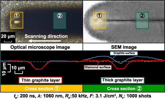
Figure 2. Appearance of a micro-groove before acid cleaning when linear scanning by round beam of Gaussian mode stopped instantly. Cross section of micro-groove before and after acid cleaning (blue cross section: before acid cleaning, red cross section: after acid cleaning).
Download figure:
Standard image High-resolution imageFigure 3 shows the appearance of a processed micro-groove behind the irradiation point, before and after acid cleaning, when the round beam of Gaussian mode was scanned at 3.1 J cm−2 laser fluence and a shot number of 100 (99.00% overlap rate). A black area was observed on both sides of the scanning line in the optical microscope image. This black area was analyzed by Raman spectroscopy, and two peaks with broad bands appeared around 1333 cm−1 and 1581 cm−1, as shown in figure 4. This Raman spectrum indicated that the black part was a graphite layer. The graphite layer was a few micrometers thick when the shapes of micro-grooves were measured before and after acid cleaning, as shown in figure 2. On the other hand, only one peak appeared at 1333 cm−1 after acid cleaning. Generally, a processed micro-groove that is covered with a lot of carbon particles is considered a low quality product. Acid cleaning can successfully remove graphite particles deposited on the surface of diamond. As can be seen in the optical microscope image after acid cleaning, the bottom of micro-groove appeared glossy, and the Raman spectroscopy analysis clarified that the micro-groove area showed the diamond crystal structure. The SEM image after acid cleaning confirmed that the bottom of the micro-groove had a low surface roughness compared with the top one, and there was no change in the pristine surface of the diamond before and after acid cleaning. Furthermore, the bottom of the micro-groove was a very flat plane perpendicular to the irradiation axis, in spite of Gaussian intensity distribution.
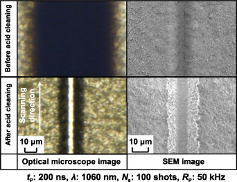
Figure 3. Optical microscope and SEM images of diamond surface after linear micro-grooving at 100 shots and 3.1 J cm−2 laser fluence by round beam of Gaussian mode.
Download figure:
Standard image High-resolution image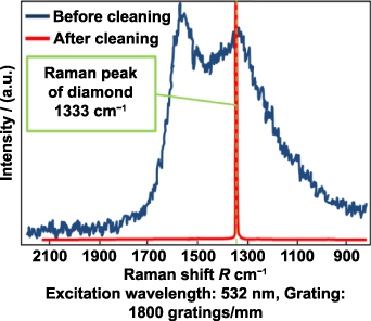
Figure 4. Raman spectra of diamond surface after linear micro-grooving at 100 shots and 3.1 J cm−2 laser fluence by round beam of Gaussian mode.
Download figure:
Standard image High-resolution imageFigure 5 shows the appearance of a micro-groove after acid cleaning for various laser fluences, when the linear micro-grooving experiments were conducted by the round beam of Gaussian mode at the same shot number of 100 shots (99.00% overlap rate). The shape of the micro-groove approached a V-shape with increased laser fluence, but a flat surface formed on the bottom plane of the processed micro-groove except at a laser fluence of 7.5 J cm−2.
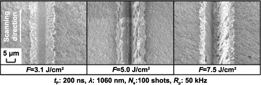
Figure 5. Appearance of micro-groove after acid cleaning for various laser fluences at 100 shots by round beam of Gaussian mode.
Download figure:
Standard image High-resolution imageFigure 6 shows the depth of the micro-groove after acid cleaning for various laser fluence. The depth of the micro-groove changed linearly with the variation of the laser fluence, and the laser fluence exhibited good control over the depth of the micro-groove. The depth of the micro-groove decreased as the laser fluence decreased. It was impossible to create a micro-groove at less than ∼2.5 J cm−2. Next, the surface roughness at the bottom of micro-groove after acid cleaning was measured by a white light interference microscope, as shown figure 7, when the line scanning experiments were carried out by the round beam of Gaussian mode at 100 shots (99.00% overlap rate) for various laser fluences. The surface roughness at the bottom of micro-groove increased as the laser fluence increased, and the most effective reduction of surface roughness occurred around the laser fluence of the removal threshold. The value of the surface roughness dropped to less than half of initial value, and the smallest surface roughness, less than 0.1 µm, was observed around the laser fluence of the removal threshold.
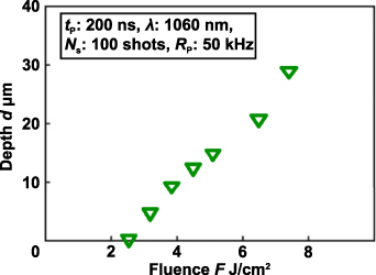
Figure 6. Depth of micro-groove for various laser fluences at 100 shots by round beam of Gaussian mode.
Download figure:
Standard image High-resolution image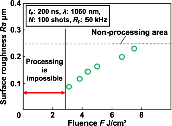
Figure 7. Variation of average surface roughness at bottom of micro-groove with laser fluence under 100 shots by round beam of Gaussian mode.
Download figure:
Standard image High-resolution imageFigure 8 shows SEM and optical microscope images of the processing front, when the laser beam irradiation of 3.1 J cm−2 laser fluence and shot number of 1000 (99.90% overlap rate) stopped instantly. The center SEM and the right optical microscope images are the same location, and the left SEM image is a highly magnified version of the center SEM image. As shown in the optical microscope image, the reflection of light was obvious at the bottom of processing front, although other areas showed low light reflection. In the magnified SEM image, the slope of the processing front seemed to be roughened, but an almost flat surface can be observed at the bottom of the processing front. The slope and bottom areas of the processing front were analyzed by Raman spectroscopy, as shown in figure 9. A g-band around 1600 cm−1 and d-band at 1333 cm−1 appeared in both areas, which are similar spectra to glassy carbon or diamond like carbon. As shown in figure 8, the surface roughness was lower at the bottom of the processing front than at the slope of the processing front. Although the material was the same, the intensity of reflected light differed by surface roughness. Hoffman et al explored the effect of laser wavelength on the ablation rate of carbon using a 10 ns pulsed laser of 355 nm, 532 nm, and 1064 nm wavelengths [14]. The laser irradiation resulted in the loss of the graphite crystalline structure, and laser beam interacted with carbon in the liquid phase at lower laser fluence. It was also mentioned that the absorption coefficient of carbon decreased at longer wavelengths in the liquid phase. Thus, it is assumed that the lower laser fluence around the removal threshold lowered the surface roughness due to the transition from thermal ablation to phase explosion, and the intensity of reflected light at the bottom of processing front became strong compared to other areas due to its small surface roughness. High reflection and low laser fluence conditions contributed to the creation of the flat bottom plane, and a continuously flat surface could be obtained around the removal threshold of diamond by near-infrared wavelength even in the case of linear micro-grooving.

Figure 8. SEM and optical microscope images of processing front at 1000 shots and 3.1 J cm−2 laser fluence by round beam of Gaussian mode.
Download figure:
Standard image High-resolution image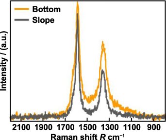
Figure 9. Raman spectra of processing front at 1000 shots and 3.1 J cm−2 laser fluence by round beam of Gaussian mode.
Download figure:
Standard image High-resolution imageOn the other hand, a V-shaped micro-groove was obtained by the reflection of the laser beam inside the micro-groove in normal laser processing of diamond [5]. A higher laser fluence would continue to removal process in the depth direction, although the reflection of the bottom plane was high. Thus, the shape of the micro-groove varied from U-shape to V-shape with increasing laser fluence, as shown in figure 5.
Figure 10 shows the SEM images and cross-sectional shapes of the micro-groove after acid cleaning for various shot numbers, when the round beam of Gaussian mode was irradiated at a laser fluence of 3.1 J cm−2. A flat bottom was obtained at all shot numbers, but the width of bottom decreased as the shot number increased. It is considered that too many shots result in a V-shaped micro-groove, and the appropriate shot number is necessary to create the flat and wide bottom of the micro-groove.

Figure 10. SEM and cross-sectional images of micro-groove after acid cleaning for various shot numbers at 3.1 J cm−2 laser fluence by round beam of Gaussian mode.
Download figure:
Standard image High-resolution imageFigure 11 shows the depth of the micro-groove after acid cleaning for various shot numbers. Around the removal threshold, the depth of the micro-groove increased drastically. At more than the removal threshold, the depth of micro-groove increased linearly up to 1000 shots (99.90% overlap rate), and it approached a constant value at more than a few thousands laser shots. Thus, efficient and controllable removal can be expected in the vicinity of the removal threshold.
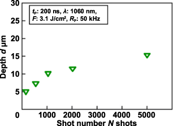
Figure 11. Depth of micro-groove for various shot numbers at 3.1 J cm−2 laser fluence by round beam of Gaussian mode.
Download figure:
Standard image High-resolution imageFigure 12 shows the variation of the average surface roughness at the bottom of the micro-groove for various shot numbers, when linear micro-grooving experiments were carried out by the round beam of Gaussian mode at a laser fluence of 3.1 J cm−2. The shape of the micro-groove approached a V-shape with increasing shot numbers, and a shallow, wide area with a flat and smooth surface could be obtained at less than 100 shots (99.00% overlap rate). It was possible to reduce the average surface roughness at the bottom of the processed micro-groove compared with the initial average surface roughness at all shot numbers, and the average surface roughness at the bottom of micro-groove was constant regardless of shot number. This indicates that lower laser fluence is a very important factor to create the flat and smooth bottom of micro-groove. It was possible to create a micro-groove with a smooth and flat surface parallel to the top surface of the specimen, although the round beam of Gaussian mode was scanned on the specimen surface perpendicular to the beam axis. Thus, the combination of nanosecond pulsed laser and acid cleaning is an effective micro-fabrication method to reduce surface roughness in addition to shaping monocrystalline diamond.

Figure 12. Variation of average surface roughness at bottom of micro-groove at various shot numbers under 3.1 J cm−2 laser fluence condition by round beam of Gaussian mode.
Download figure:
Standard image High-resolution image3.2. Processing characteristics by square beam of top-hat mode
As mentioned before, although the round beam of Gaussian mode was used, a flat and smooth surface was obtained on the perpendicular plane to the irradiation axis. However, in order to identify the most efficient creation method of a flat and smooth surface, a square beam of top-hat mode was considered instead of the round beam of Gaussian mode, as shown in figure 1(b). The main processing conditions and the definition of shot number were the same as the experiments that used the round beam of Gaussian mode, and the micro-grooves processed by the square beam of top-hat mode were evaluated.
Figure 13 shows the SEM images of a micro-groove processed by single line scanning after acid cleaning. The shot number was set to 100 shots (99.00% overlap rate), and the laser fluence varied from 7.5 to15 J cm−2. A smooth and flat area formed at the bottom of the processed micro-groove. The slope areas at both sides of the processed micro-groove increased as the laser fluence increased, while the wide area of the flat bottom was obtained at a lower laser fluence of 7.5 J cm−2. The effective creation of a wide flat surface on the bottom plane of the micro-groove was possible at a lower laser fluence.
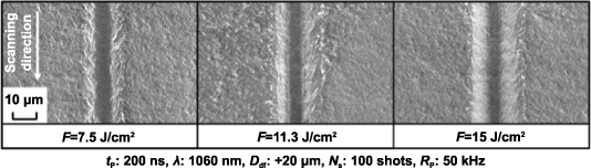
Figure 13. SEM images of diamond surface after acid cleaning for various laser fluences at 100 shots by square beam of top-hat mode.
Download figure:
Standard image High-resolution imageFigure 14 shows the variation of average surface roughness at the bottom of the micro-groove after acid cleaning, when the laser fluences were varied at a shot number of 100 (99.00% overlap rate) in the scanning experiment by the square beam of top-hat mode. The average surface roughness decreased below approximately half of the initial value, and it was possible to reduce the average surface roughness at the bottom of micro-groove around the laser fluence of removal threshold, in the same phenomena as the round beam of Gaussian mode. The square beam of top-hat mode required higher laser fluence to produce the flat plane due to the different beam mode, but the processing window (above 7 J cm−2) to achieve the most effective reduction of surface roughness was wider than that of the round beam of Gaussian mode (less than 1 J cm−2).

Figure 14. Variation of average surface roughness at bottom of micro-groove with various laser fluences under 100 shots by square beam of top-hat mode.
Download figure:
Standard image High-resolution image3.3. Comparison of micro-groove shape around fluence of removal threshold
The micro-groove shapes processed by the round beam of Gaussian mode and the square beam of top-hat mode were compared, when the wide, flat surface was effectively created at the bottom of micro-groove. The width to depth aspect ratio of the micro-groove was obtained by measuring the bottom width and the depth of the micro-groove. In addition, the generating ratio of bottom flat surface to the spot diameter was calculated by the equation (1), and the ratio of the bottom width to the top width were calculated by the equation (2):
In the case of the square beam of top-hat mode, the side of the square beam was used as the spot diameter size in the equation (1).
The calculation results of these three evaluation factors are shown in figure 15. The aspect ratio of the square beam of top-hat mode was smaller than that of the round beam of Gaussian mode, which means that a wide, flat surface can be formed at the bottom of the micro-groove against the laser spot. In addition, the square beam of top-hat mode had larger values of both the generating ratio of the bottom surface and the ratio of bottom to top widths. Thus, it can be said that the square beam of top-hat mode can obtain a shallow and straight U-shaped micro-groove with a wide, flat bottom The ratio of the bottom width to the spot size was larger in than the round beam of Gaussian mode. Moreover, robust processing can be expected with a wide processing window of laser fluence.

Figure 15. Comparison of micro-groove shapes around removal threshold at each beam mode.
Download figure:
Standard image High-resolution image4. Formation of a wide, flat area with a smooth surface by repeating linear micro-grooving with the square beam of top-hat mode
Area formation was investigated by repeating the linear micro-grooving with the square beam of top-hat mode, and the shape of the processed micro-groove is schematically shown in figure 16(a). When the liner micro-grooving experiment was carried out at the laser fluence of 7.5 J cm−2 and a shot number of 100 (99.00% overlap rate), the top width, bottom width, and depth of the processed line were 20 µm, 5.3 µm, and 5.2 µm, respectively. Figure 16(b) shows a schematic illustration of the micro-groove shape in the case of side-by-side line scanning at a pitch distance of 5.0 μm when the number of scanning lines increased in the left direction from the right side. The green hatched section indicates the removal region in the second line scanning, when the same removal region by the first line scanning is assumed. A 5.0 µm pitch distance is enough to continue the bottom of the micro-groove for to form a wide, flat area under this processing conditions.

Figure 16. Formation of micro-groove shape in the case of side-by-side line scanning. (a) Shape of micro-groove by the first line scanning. (b) Assumed removal region by the second line scanning.
Download figure:
Standard image High-resolution imageFigure 17 shows the cross-sectional shapes of the irradiation area in the case of side-by-side line scanning at pitch distances of 5.0 μm and 10 μm, when linear micro-grooving was repeated five times from the right to left side at 7.5 J cm−2 fluence and 100 shots. As mentioned in the experimental procedures, compressed air was supplied from the left side of the figure to remove deposits of graphite debris from the next processing line. As shown in the SEM images and cross-sectional shapes, the depth of the processed line increased as the number of lines increased compared with the first line, at the pitch distance of 5.0 μm, which was shorter than the bottom width of one processed line. When the pitch distance of 10 µm is longer than the bottom width of one processed line, a linearly convex region remained between the processed lines. As mentioned in the figure 16(b), the assumed removal region of the second scanning line partially overlapped the removal region of the first line, and the height level of the irradiation surface in the second scanning line was smaller than that of the first one. Thus, it is difficult to avoid increasing the depth of subsequent line when increasing the number of lines, when the linearly convex regions between processed lines were not formed. The normal side-by-side repetition of linear micro-grooving cannot create a wide, flat area with a smooth surface. Next, a two-step scanning method was discussed to obtain the constant removal depth for the wide area.
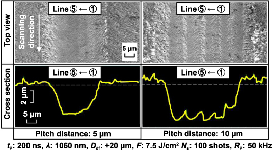
Figure 17. Appearance and cross-sectional shapes of irradiation area in the case of side-by-side line scanning at 7.5 J cm−2 laser fluence and 100 shots at pitch distance of 5.0 μm and 10 μm.
Download figure:
Standard image High-resolution imageIn order to overcome the problems of the normal side-by-side repetition of linear micro-grooving, a new two-step scanning method was proposed. It is necessary that the removal depth should be similar in all processing lines to obtain a flat surface, and the subsequent micro-grooving should be conducted on the specimen surface at a similar height to the first processing line. Figure 18 schematically shows the location of the scanning line and the shape of the micro-groove in the two-step scanning method of 5 lines. As shown in figure 18(a), linear micro-grooving experiments were conducted at the location of 1, 3, and 5 lines in the first step, and three comb-shaped micro-grooves were obtained. After the first step, the non-removal surface retained its initial height level at the regions between the processed lines. In the second step, linear micro-grooving was carried out at lines 2 and 4, as shown in figure 18(b). Non-removal areas were partially retained between the processing lines in the first step, and laser scanning was conducted in the retained area in the second step. Then, a wide, flat area formed on the bottom plane of the processed area.
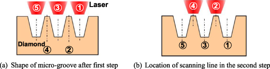
Figure 18. Location of scanning line and shape of micro-groove in two-step scanning method of 5 lines. (a) Shape of micro-groove after the first step. (b) Location of scanning line in the second step.
Download figure:
Standard image High-resolution imageIn order to determine the processing conditions, the top width, bottom width, and depth of the micro-groove were investigated by changing the laser fluence and shot number. Then, the laser fluence and shot number in the first step were set to 7.5 J cm−2 and 35 shots (97.15% Overlap rate) at a pitch distance of 16 μm. The irradiation conditions of the second step were set to 6.0 J cm−2 laser fluence and 35 shots (97.15% overlap rate). As shown in figure 18, the first step created three micro-grooves, and the non-removal areas of the initial surface remained between the linear micro-grooves. The positions of the processing lines in the second step were set at the centers of the retained areas from the first step, and the second step was conducted. After the second step, a continuous flat area with small convexities below 50 nm step was successfully formed, as shown in figure 19. The newly proposed two-step scanning method by square beam of top-hat mode was practical and useful to create a wide, flat plane with low surface roughness, and it improved the controllability of the micro-groove depth. This proposed method can reduce the surface roughness in addition to the shape creation of monocrystalline diamond, and it can be used as a high-quality micro-shape fabrication method of monocrystalline diamond.

Figure 19. Appearance and cross-sectional shapes of irradiation area by two-step scanning method at 16 μm pitch distance.
Download figure:
Standard image High-resolution image
5. Conclusions
In this study, a high-quality micro-processing method of monocrystalline diamond was experimentally investigated to obtain low surface roughness in addition to the shape creation process by the nanosecond pulsed laser, and the influence of intensity distribution on the removal characteristics of monocrystalline diamond was discussed. Furthermore, the creation method of a flat, wide area by the arrangement strategy of linear micro-grooving was investigated. The conclusions are as follows:
- (a)A flat plane with low surface roughness, below 0.1 µm average roughness, was obtained for monocrystalline diamond by nanosecond pulsed laser irradiation of 1060 nm and post-process acid cleaning, at a laser fluence around the threshold value of material removal.
- (b)Square beam of top-hat mode produced a micro-groove with a low aspect ratio and flat bottom. This method has a wider processing window for the most effective reduction of surface roughness compared with round beam of Gaussian mode.
- (c)It is important to maintain an equal removal depth of subsequent micro-grooving in the shape creation process of a wide area. Using the proposed two-step scanning method for repeated linear micro-grooving maintained the removal height in each scanning step, which effectively created a wide, flat plane with low surface.
Acknowledgments
The authors would like to express their sincere thanks to Dr. Togo Shinonaga and Mr. Koji Tabuchi, Nontraditional Machining Laboratory, Okayama University for their contribution to the experiments. This work was partially supported by Osawa Scientific Studies Grants Foundation.