

Abstract
Diabetes mellitus is a disorder in which the body does not produce enough or respond normally to insulin; consequently, blood glucose levels increase to become abnormally high. Accordingly, the primary treatment of diabetes is to control glycemic levels continuously. To continuously control glycemic levels, several medical devices have been developed to monitor blood glucose levels, represented by sensors and monitors for the self-monitoring of blood glucose. The ultimate goal for those engaged in research to develop medical devices is to develop implantable biodevices, namely self-powered autonomously operated artificial pancreas systems. One of the most challenging issues in realizing an implantable artificial pancreas is the long-term continuous supply of electricity, which is currently dependent on rechargeable batteries, requiring periodical replacement. In this work, we report the development of a direct electron transfer type enzyme-based miniaturized self-powered glucose sensor based on the BioCapacitor principle with a micro-sized enzyme anode area (0.15 mm × 0.75 mm), which has only 0.1 mm2 of electrode surface. As a result, a BioCapacitor utilizing a biofuel cell with a micro-sized enzyme anode was operated by self-power. In addition, the glucose concentration was detected within the range from 13 mM to 100 mM based on the frequency of charge/discharge cycles of the BioCapacitor. Although further improvement of the current density of the micro-sized anode is necessary to monitor a glucose concentration range lower than 13 mM, this self-powered glucose sensor with a micro-sized electrode based on the BioCapacitor principle was operated continuously for 6.6 h at 37 °C in 100 mM potassium phosphate buffer (pH 7.0). Our success indicates the potential to realize self-powered, autonomous, and implantable sensing modules for bio devices such as glucose-sensing systems for an artificial pancreas.
Export citation and abstract BibTeX RIS

Original content from this work may be used under the terms of the Creative Commons Attribution 4.0 license. Any further distribution of this work must maintain attribution to the author(s) and the title of the work, journal citation and DOI.
1. Introduction
Diabetes mellitus is a disorder in which the body does not produce enough or respond normally to insulin; consequently, blood glucose levels increase to become abnormally high. Accordingly, the primary treatment of diabetes is to control glycemic levels continuously. The current gold standard for controlling glycemic levels is the continuous glucose monitoring (CGM), which measures glucose concentration in the interstitial fluid, continuously, allowing for real-time therapy. This began with the first 'Professional' CGM, which was approved by the US Food and Drug Administration in 1999. This first wave of CGMs were lacking in accuracy and stability, but over the years have greatly improved due to various innovations [1]. Currently, most commercially available CGM systems employ enzyme electrochemical sensing principles, and can continuously monitor glycemic levels in interstitial fluid for 7–14 days. Recently, a fluorescence-based CGM system was approved and can be used for up to 90 days in the US and 180 days in Europe.
With the advancement of CGM accuracy, stability, and reproducibility, the idea of a CGM being the core component in the realization of an artificial pancreas has arisen. Since the first concept of an implantable artificial pancreas comprising a glucose monitoring device, transmitter and insulin syringe was established by Professor E Perry McCullagh in 1959, the bedside-type artificial endocrine pancreas was developed [2–9]. The bedside-type artificial endocrine pancreas was extremely useful as a research tool and for therapeutic treatment; however, patients had a restriction on movement during treatment due to the size of the system. A recent method using a CGM is the sensor augmented insulin pump control. In 2016, the US Food and Drug Administration approved a hybrid closed-loop system consisting of a CGM calibrated by self-monitoring of blood glucose, a control algorithm, and an insulin pump as the first generation of an artificial pancreas device system. This system made it possible to control blood glucose levels continuously and automatically.
So what should be the next step for an artificial pancreas system? For those involved or engaged in such research, the longstanding goal is to develop an implantable biodevice [10–13]. Like the modern pacemaker, this device would integrate mechanical, electrical, telecommunication, control and computer systems into a single elegant device. This type of system is also the next goal for the artificial pancreas, integrating a CGM, insulin infusion system, and control algorithms into a single implantable biodevice. Thanks to recent advances in both CGMs and control algorithms, hybrid closed-loop systems that integrate insulin delivery and glucose monitoring are now available to patients. However, there has been very little headway made in the development of an implantable device, as all the current systems are worn outside the body. In parallel to improvements in CGMs, research in developing implantable reservoirs and micropumps has also been reported [14, 15]. This suggests that with further research and improvements, an implantable biodevice for blood glucose control could potentially be developed.
One of the challenging issues in realizing an implantable artificial pancreas is finding a method to support long-term continuous supply of electricity, which currently depends on a rechargeable battery, requiring periodical replacement. The advanced development of low-power consumption equipment, potentiostats and actuators has been reported. For example, a stepping motor, such as a quartz watch stepping motor used for a watch (e.g. Super 2035 movement (CITIZEN WATCH CO. LTD, Tokyo, Japan)), which has 0.83 nAh of average current consumption, was used as an actuator for a micro-infusion pump such as iPRECIO® (Primetech Corp., Tokyo, Japan). These innovations have made it possible to extend the lifetime of biodevices; however, regular external battery replacement is still inevitable. To avoid regular external battery replacement, an alternative electricity supply system should be developed to realize autonomously operated implantable biodevices.
Enzyme fuel cells, which generate electrical power from biological substances, such as glucose, lactate, alcohol etc, have received attention as an attractive alternative energy source, particularly for self-powered autonomous implantable biosensors. Enzyme-based fuel cells use immobilized enzymes as electrocatalysts on the surface of both the anode and cathode electrodes. However, enzyme fuel cells have the inherent drawback that the theoretical voltage of a single enzyme fuel cell is low because the voltage of the biofuel cell depends on the redox potential of cofactors and mediators. Unlike current, which is relatively easy to increase by electrode surface modification with carbon and conductive materials, the voltage is much more difficult to increase. In particular, considering that most electrical devices usually require over 1.8 V to successfully operate, the most crucial issue when a biofuel cell operates an electrical device is the lack of enough voltage. To improve the voltage output, researchers have tried approaches such as placing several biofuel cells in series [16]. Abreu et al successfully demonstrated this principle by placing two biofuel cells in series, producing 1.35 V and 1.82 ± 0.09 mW of power. Although this approach can generate higher voltage and power, the biofuel cell can get larger and more complex, which is not suitable for implantable biodevices. To overcome this enzyme fuel cell limitation, we reported a novel principle for a biosensor termed 'BioCapacitor', which connects an enzyme fuel cell to a capacitor via a charge pump [17–21]. In the BioCapacitor, the charge pump steps up the voltage, and the power generated from the enzyme fuel cell is charged in a capacitor. When the voltage of the capacitor reaches the discharge start voltage (∼1.8 V), the charge pump switches the circuit and discharges the capacitor. After discharge, the charge pump switches the circuit and begins recharging the capacitor. By repeating charge and discharge cycles, a high voltage with enough temporary power can be generated by a single enzyme fuel cell. The BioCapacitor concept allows the entire structure of biofuel cells to be much smaller and simpler compared to stacking multiple biofuel cells in series. Starting from the first report introducing the principle of BioCapacitor, BioCapacitor has been widely applied for many researches developing self-powered biodevices based on enzyme fuel cells [17, 22, 23], and it is one of the representative and essential technologies in the field [24]. Furthermore, BioCapacitor has been motivated to develop other hybrid electric power devices such as Biosupercapacitor [25–30]. Using the BioCapacitor principle, we also reported an autonomous and self-powered wireless glucose-sensing system [18–20], actuator (stepper motor) [21] and microcontroller [31] using glucose as a sole energy source.
Our previous reports have shown the potential for development of those modules corresponding to a self-powered autonomous sensor module, actuator module and control module, and we expect that it will finally lead to the development of an implantable artificial pancreas device system operated autonomously and self-powered.
To apply the BioCapacitor principle to an implantable artificial pancreas device, the biofuel cell must be miniaturized. However, due to power and current being dependent on the electrode surface area, the improvement of power and current may be limited by micro-sized electrodes. Therefore, it is necessary to develop a miniaturized biofuel cell that can generate sufficiently high current and power in order to operate a BioCapacitor circuit. In this work, we report the development of a self-powered glucose sensor based on the BioCapacitor principle with a micro-sized enzyme anode which has only 0.1 mm2 of electrode surface area (0.15 mm × 0.75 mm). To achieve a micro-size enzyme anode that can generate sufficient power to operate a BioCapacitor circuit, we applied multiple enzyme layers combining our original enzyme, direct electron transfer (DET) type flavin adenine dinucleotide (FAD) dependent glucose dehydrogenase (FADGDH), derived from Burkholderia cepacia [32–37] and carbon black. We then attempted to detect various glucose concentrations with a self-powered glucose sensor based on the BioCapacitor principle with a micro-sized enzyme anode. Finally, we demonstrated continuous operation of the system.
2. Methods
2.1. Materials
In this study, bacterial FADGDH was used, which is capable of DET. FADGDH comprises three subunits, namely the catalytic subunit, the cytochrome c subunit, and the small subunit. A recombinant FADGDH complex was prepared using the expression vectors pTrc99A, containing the structural genes for the FADGDH complex, and pAYCYC184, containing the structural genes for cytochrome c maturation (pEC86); the vectors were transformed into E. coli strain BL21 (DE3) and cultivated as previously described [32]. The FADGDH complex has an activity of 365 U mg−1. Bilirubin oxidase (BOD) was kindly donated by Amano Enzyme Inc. (Aichi, Japan). Ketjen black, ECP600JD (Brunauer–Emmett–Teller surface area: 1270 m2 g−1) was purchased from Mitsubishi Chemical Corporation (Tokyo, Japan). The micro-sized gold electrode with the length and width of the gold electrode surface window is 0.15 mm and 0.75 mm, with electrode surface area: 0.1 mm2, which was fabricated by gold sputtering coating and covered by insulator except for the electrode surface area. Ag/AgCl reference electrodes were purchased from BAS Inc. (Tokyo, Japan). Further, 25% (w/v) glutaraldehyde solution was purchased from Wako Pure Chemical Industries, Ltd (Osaka, Japan), and Triton X-100 was purchased from Kanto Chemical (Tokyo, Japan). Carbon cloth, SYCC18-00000-00, was provided from Toho Tenax (Tokyo, Japan).
2.2. Preparation of enzyme anode and cathode
The enzyme anode was prepared using FADGDH complex immobilized Ketjen black, which is highly electro-conductive carbon black, as follows. About 0.4 µg of Ketjen black particles were mixed with 19.4 mg ml−1 FADGDH complex and then the enzyme solution was incubated for 1 h at 25 °C. Next, 2% sucrose and 20 mM Sorensen's phosphate buffer (pH 5.8) were added to the enzyme solution. A total of 0.05 µl of enzyme solution was dropped onto the micro-sized gold sputtered electrode (0.1 mm2) and the electrode was dried for 30 min at 25 °C. We carried out this procedure three more times so that we were able to prepare the microneedle electrode-immobilized four layers of enzyme . The electrode was cross-linked in 25% glutaraldehyde vapor for 1 h and washed with 10 mM Tris–HCl buffer (pH 7.0). The enzyme anode was then stored in 100 mM potassium phosphate buffer (PPB; pH 7.0) until use.
The enzyme cathode was prepared using BOD immobilized Ketjen black, as follows. Ketjen black carbon ink was prepared by mixing 15 mg of Ketjen black with 670 μl of ultrapure water and 30 μl of Triton X-100. 200 μl of Ketjen black ink, 300 μl of 20 mg ml−1 BOD solution, and 500 μl of 100 mM PPB (pH 7.0) were mixed, and then 200 μl of this solution was dropped onto a carbon cloth (electrode surface: 4 cm2) which weaves carbon fiber. After the electrode was dried for 1 h, the electrode was cross-linked in 25% glutaraldehyde vapor for 1 h and washed with 10 mM Tris–HCl buffer (pH 7.0). The cathode was then stored in 100 mM PPB (pH 7.0) until use.
2.3. Electrochemical characterization of the enzyme anode
The output of the enzyme anode was evaluated by chronoamperometry. Chronoamperometric evaluation of the enzyme anode (+0.4 V vs Ag/AgCl) was conducted using a 10 ml water jacket cell. The constructed anode, Ag/AgCl, and Pt wire were used as a working electrode, a reference electrode, and a counter electrode, respectively, and then the current change was monitored in the presence of different glucose concentrations.
To evaluate the stability of the enzyme anode, continuous chronoamperometric measurements were carried out. Chronoamperometric evaluation of the enzyme anode (+0.4 V vs Ag/AgCl) was conducted using a 10 ml water jacket cell. The constructed anode, Ag/AgCl, and Pt wire were used as a working electrode, a reference electrode, and a counter electrode, respectively. The reaction buffer contained 20 mM glucose, and the generated current was monitored continuously for 20 h.
All electrochemical characterizations were performed at 37 °C in 100 mM PPB (pH 7.0)
2.4. Closed-circuit voltage and polarization curve measurement of the enzyme fuel cell
To construct the enzyme fuel cell, the enzyme anode and cathode were immersed in a 10 ml water jacket cell including 100 mM PPB (pH 7.0) as the reaction buffer. Next, the enzyme anode was connected to the enzyme cathode and the change of closed-circuit voltage was monitored under various glucose concentrations.
To investigate the polarization curve of the enzyme fuel cell, the enzyme anode and cathode were immersed in a 10 ml water jacket cell in the same way as closed-circuit voltage measurements. 100 mM PPB (pH 7.0) containing 20 mM glucose was used as the reaction solution. Next, the enzyme fuel cell was connected to an external variable-load resistance (100 Ω–1 MΩ) (model 278620; Yokogawa Electric Corporation, Tokyo, Japan), and the voltage generated by the enzyme fuel cell was measured. The polarization curve was measured by monitoring the current and voltage of the biofuel cell by changing resistances. All electrochemical characterizations were performed at 37 °C in 100 mM PPB (pH 7.0)
2.5. Glucose concentration monitoring of self-powered glucose sensor with micro-sized electrode based on BioCapacitor principle
To construct the enzyme fuel cell, an enzyme immobilized anode and cathode were immersed in a 10 ml water jacket cell including 100 mM PPB (pH 7.0) as the reaction buffer. Next, the enzyme fuel cell was connected in series with a 1 µF capacitor and charge pump integrated circuit (IC; S-882Z18M5T1G, Seiko Instruments, Chiba, Japan). The voltage of the enzyme fuel cell was increased in a stepwise manner by the charge pump, and the generated electricity was used to charge the 1 µF capacitor. The charge pump circuit was connected to a light-emitting diode (LED) to visually confirm the operation of the BioCapacitor. The charge/discharge frequency was calculated by monitoring the voltage over the 1 µF capacitor.
All electrochemical characterizations were performed at 37 °C in 100 mM PPB (pH 7.0)
2.6. Continuous operation utilizing self-powered glucose sensor with micro-sized electrode based on BioCapacitor principle
To construct the enzyme fuel cell, the enzyme immobilized anode and cathode were immersed in a 10 ml water jacket cell. 100 mM PPB (pH 7.0) containing 20 mM glucose was used as the reaction solution. Next, the enzyme fuel cell was connected in series with a 1 µF capacitor and charge pump IC (S-882Z18M5T1G, Seiko Instruments, Chiba, Japan). The voltage of the enzyme fuel cell was increased in a stepwise manner by the charge pump, and the generated electricity was charged into a 1 µF capacitor. The charge pump circuit was connected to the LED to visually confirm operation of the BioCapacitor. The charge/discharge cycles were monitored by continuous monitoring of the voltage over the 1 µF capacitor.
All electrochemical characterizations were performed at 37 °C in 100 mM PPB (pH 7.0)
3. Result and discussion
3.1. Electrochemical characterization of the enzyme anode and enzyme fuel cell
To achieve higher current density from a micro-sized enzyme anode, the FADGDH complex was immobilized onto Ketjen black particle directly and then the ink consisting of Ketjen black and enzyme was deposited onto the micro-sized electrode surface as four layers. Figure 1(A) shows the time course of chronoamperometric evaluation of the enzyme immobilized anode toward the glucose. An immediate current increase was observed with the addition of glucose due to DET from the enzyme to electrode surface. The increase in catalytic current due to DET of the enzyme was also confirmed using cyclic voltammograms (CVs) (supplementary information figure S1 (available online at stacks.iop.org/JPENERGY/3/034009/mmedia)). From CV of bovine serum albumin immobilized electrodes, no catalytic current increase was observed in the presence of glucose (supplemental information, figure 1(A)). In contrast, a clear catalytic current increase was observed in the DET type FADGDH immobilized electrode in the presence of glucose (supplemental information, figure 1(B)), confirming that the current increase is due to enzymatic reaction.
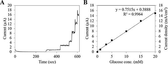
Figure 1. Chronoamperometric evaluation of micro-sized enzyme anode employing direct electron transfer FADGDH. (A) Representative time course of micro-sized enzyme anode employing direct electron transfer FADGDH in the presence of 1, 3, 5, 10, 15 and 20 mM glucose at +400 mV (vs Ag/AgCl) in 100 mM potassium phosphate buffer (pH 7.0), 37 °C. (B) Representative calibration curve of micro-sized enzyme anode employing direct electron transfer FADGDH in the presence of 1, 3, 5, 10, 15 and 20 mM glucose at +400 mV (vs Ag/AgCl) in 100 mM potassium phosphate buffer (pH 7.0), 37 °C.
Download figure:
Standard image High-resolution imageAn increase in the catalytic current was observed from around −0.2 V (vs Ag/AgCl), and the current was drastically increased within the range from −0.2 V to 0.4 V (vs Ag/AgCl). After that the current was gradually increased within the range from 0.4 V to 0.6 V (vs Ag/AgCl). Although 0.6 V (vs Ag/AgCl) can provide higher current than +0.4 V (vs Ag/AgCl), there is no big difference in current. Furthermore, a higher applied potential causes a high number of enzyme turnover, which may cause enzyme inactivation; therefore, we chose +0.4 V (vs Ag/AgCl), which showed sufficiently high current and may be less harmful for enzyme than +0.6 V (vs Ag/AgCl). Furthermore, the enzyme electrode with Ketjen black showed a larger CV response (supplementary information figure S1(C)), representing high capacitance of the electrode with Ketjen black. Thanks to the high capacitance behavior of the enzyme immobilized electrode with Ketjen black, high maximum power and current density can be achieved. Additionally, since the DET FADGDH immobilized Ketjen black modified electrode showed a larger CV response compared with the enzyme immobilized electrode without Ketjen black, the increase in capacitance behavior may be attributed to the addition of Ketjen black. The micro-sized enzyme immobilized anode exhibited a high current (15 µA) and high current density (15 mA cm−2) in the presence of 20 mM glucose, and showed a linear correlation between current and glucose concentration (figure 1(B)).
The stability of the micro-sized enzyme electrode was then investigated in the presence of 20 mM glucose at 37 °C. Figure 2 shows the time course of continuous operation of the micro-sized enzyme anode. Although the current decreased during the initial 5 h of operation, the micro-sized enzyme anode was able to retain approximately 9.2 µA (9 mA cm−2) after 20 h of continuous operation at 37 °C. These results demonstrated that the multiple layers consisting of Ketjen black and enzyme were stably maintained on the micro-sized electrode surface.

Figure 2. Chronoamperometric evaluation of the stability of micro-sized enzyme anode employing direct electron transfer type FADGDH. Representative time course of micro-sized enzyme anode employing direct electron transfer type FADGDH for 20 h. Current was monitored continuously at glucose at +400 mV (vs Ag/AgCl) in 100 mM potassium phosphate buffer (pH 7.0) containing 20 mM glucose, 37 °C.
Download figure:
Standard image High-resolution imageNext, the glucose biofuel cell was constructed with a micro-sized enzyme immobilized anode employing DET type FADGDH. Figure 3 shows the representative polarization curve of the enzyme fuel cell with a micro-sized anode. The dependence of the power and current on the cell voltage revealed that the open-circuit voltage was 658 mV and the maximum current density and maximum power density were 18 mA cm−2 and 3.5 mW cm−2, respectively. This maximum current and power density are among the highest performance compared with currently reported biofuel cells [38–40]. Shitanda et al reported a lactate-based enzyme fuel cell which achieved 4.3 mW cm−2 of maximum power density with the lactate concentration at 300 mM [41]. This lactate concentration will not be observed in in vivo (blood or interstitial fluid) samples, but probably will under some specific conditions such as accumulated urine and lactate in diapers.

Figure 3. Electrochemical evaluation of biofuel cell with micro-sized enzyme anode employing direct electron transfer type FADGDH. Representative polarization curve of an enzyme fuel cell with micro-sized enzyme anode employing direct electron transfer type FADGDH. The electrochemical evaluation was carried out in the 100 mM potassium phosphate buffer (pH 7.0) containing 20 mM glucose at 37 °C. Filled squares show the dependence of current density on cell voltage and open squares show the dependence of power density on cell voltage.
Download figure:
Standard image High-resolution imageConsidering that the charge pump IC circuit is used in this study, the voltage of the enzyme fuel cell is boosted up from 300 mV to 1.8 V. In other words, the minimum input voltage must be higher than 300 mV to operate the charge pump IC equipped with the BioCapacitor circuit. To confirm whether the micro-sized biofuel cell using an enzyme immobilized anode produced sufficient voltage to operate the charge pump IC, a closed-circuit biofuel cell was investigated. Figure 4 shows that the closed-circuit voltage changes in the presence of various glucose concentrations. The closed-circuit voltage reached 369 mV in the presence of 0.2 mM glucose and gradually increased, reaching 461 mV in the presence of 20 mM glucose. Since the closed-circuit voltage already reached 369 mV in the presence of 0.2 mM glucose, it was determined that biofuel cell with a micro-sized enzyme anode can generate sufficient voltage to operate the charge pump IC even at 0.2 mM glucose.

Figure 4. Investigation of closed-circuit voltage of biofuel cell with micro-sized enzyme anode employing direct electron transfer type FADGDH. Representative closed-circuit voltage of an enzyme fuel cell with micro-sized enzyme anode employing direct electron transfer type FADGDH. The closed closed-circuit voltage was investigated in 100 mM potassium phosphate buffer (pH 7.0) containing 0, 0.2, 0.4, 1, 2, 3, 4, 5, 10, 15 and 20 mM glucose at 37 °C.
Download figure:
Standard image High-resolution image3.2. Glucose concentration monitoring utilizing self-powered glucose sensor with micro-sized electrode based on BioCapacitor principle
Next, a BioCapacitor utilizing biofuel cell with a micro-sized enzyme immobilized anode was operated. To confirm the operation of the BioCapacitor, the voltage of the capacitor was investigated in the presence of various glucose concentrations. The voltage of the capacitor was increased by adding glucose, and it reached 1 V with 5 mM of glucose. The voltage of the capacitor kept increasing up to 1.8 V in the presence of 11.4 mM glucose, and then the first discharge was observed. The repeated charge and discharge cycles were observed at concentrations higher than 13 mM glucose, and the BioCapacitor carried out charging and discharging the electricity from 1.1 V to 1.8 V repeatedly (figure 5(A)). Figure 5(B) shows the correlation between the frequency of charge/discharge cycles and glucose concentration. The frequency of charge/discharge cycles increased with increasing glucose concentration, and the glucose concentration was detected within the range from 13 mM to 100 mM based on the frequency of charge/discharge cycles of the BioCapacitor.

Figure 5. Investigation of the charge/discharge cycles of BioCapacitor connected to biofuel cell with micro-sized enzyme anode employing direct electron transfer FADGDH. (A) Representative time course of BioCapacitor operation with micro-sized enzyme anode employing direct electron transfer FADGDH. To confirm the operation of BioCapacitor, the voltage of the capacitor was investigated in 100 mM potassium phosphate buffer (pH 7.0) containing various glucose concentrations at 37 °C. Inset figure shows enlarged time course from 780 s to 800 s where the first repeated charge/discharge was repeatedly observed. (B) Representative correlation between the frequency of charge/discharge cycles and log(Glucose conc.(mM)). The correlation between the frequency of charge/discharge cycles and glucose concentration was investigated in 100 mM potassium phosphate buffer (pH 7.0) at 37 °C.
Download figure:
Standard image High-resolution imageThe detection limit of glucose measurement using the self-powered glucose sensor based on the BioCapacitor principle greatly depends on the generated voltage and power from the biofuel cell, because the charge/discharge cycle was observed only when the charge pump IC was operated by biofuel cell. Due to this limitation, at glucose concentrations lower than 11.4 mM, the power of the biofuel cell did not reach the minimum power consumption of the charge pump IC to switch the BioCapacitor circuit. As demonstrated in figure 4, the minimum input voltage (300 mV) is required to operate the charge pump IC. As the closed-circuit voltage of the biofuel cell reached 369 mV in the presence of 0.2 mM glucose concentration, the biofuel cell with the micro-sized enzyme immobilized anode was able to generate sufficient voltage to operate the charge pump IC even at the lower glucose concentration. However, the current generated by the micro-electrode would not be enough to initiate the charge/discharge cycle of the charge pump circuit IC. Considering the currently available technologies to increase the current density of biofuel cells by increasing the surface area and conductivity [42, 43], the tuning of the detection range of self-powered and miniaturized glucose sensors will be possible by additional combination of these technologies.
3.3. Continuous operation utilizing self-powered glucose sensor with micro-sized electrode based on BioCapacitor principle
Figure 6 shows the time course of the continuous operation of a self-powered glucose sensor with a micro-sized electrode based on the BioCapacitor in the presence of 20 mM glucose at 37 °C. A repeated charge/discharge cycle was observed for 6.6 h. After that, although the voltage of the capacitor was kept at 1.8 V, repeated discharge was not observed.

Figure 6. Continuous operation of self-powered glucose sensor with micro-sized enzyme anode employing direct electron transfer FADGDH. Representative time course of self-powered glucose sensor for 8 h. The continuous operation was carried out in 100 mM potassium phosphate buffer (pH 7.0) containing 20 mM glucose at 37 °C and the voltage of capacitor was monitored continuously.
Download figure:
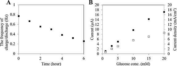
Standard image High-resolution imageFigure 7(A) shows the frequency change of the charge/discharge cycle during continuous operation of 6 h. The initial frequency of the charge/discharge cycle was 0.8 Hz, and it decreased linearly with time. Since the frequency of the charge/discharge cycle depends on the time required to charge the capacitor with biofuel cell, the observed decrease in the frequency revealed the decrease in the catalytic activity at either the anode or cathode reaction under the operation at constant glucose concentration. Figure 7(B) shows the comparison of the micro-sized enzyme immobilized anode before or after 8 h of continuous operation. Although the current from the micro-sized enzyme immobilized anode decreased after continuous operation, the micro-sized enzyme immobilized anode kept about 50% of current density (8.6 µA) compared with the initial status (17 µA) at glucose concentration of 20 mM, which was consistent with the results of continuous chronoamperometric operation (figure 2). The operational stability of the BioCapacitor with a micro-sized bioanode is similar compared with other reported self-powered devices (5–7 h), which generated electricity by repeating charge/discharge [44, 45]. Considering that the lifetime of current commercially available CGM sensors is 7–14 days, the further improvement of operational stability will be mandatory for use in vivo as an implantable device.
Figure 7. Investigation of the frequency of charge/discharge cycle during continuous operation and the performance of micro-sized enzyme anode before/after continuous operation. (A) Representative correlation between the frequency of charge/discharge and time during continuous operation. The frequency of the charge/discharge cycle was investigated in 100 mM potassium phosphate buffer (pH 7.0) containing 20 mM glucose at 37 °C. (B) Representative calibration curve of micro-sized enzyme anode employing direct electron transfer FADGDH in the presence of 1, 3, 5, 10, 15 and 20 mM glucose at +400 mV (vs Ag/AgCl) in 100 mM potassium phosphate buffer (pH 7.0), 37 °C. Closed squares show the calibration curve before starting continuous operation, and open squares show the calibration curve after 8 h continuous operation.
Download figure:
Standard image High-resolution image
Considering the discrepancy between the operational stability of the anode alone and those of the BioCapacitor configuration shown in figure 7(A), these results indicate that the stability of the cathode might determine the operational stability of the system. However, recent achievements in the improvement of enzyme cathode performances [46, 47] will be further utilized to enhance the operational stability of self-powered glucose sensors with micro-sized electrodes based on the BioCapacitor principle and will be greatly improved with further investigation and improvement of the enzyme cathode.
In summary, these results demonstrated that a miniaturized electrode-based BioCapacitor employing DET-type FADGDH can be constructed and operated continuously. We believe that our success in continuous operation of self-powered glucose sensors based on the BioCapacitor principle using micro-sized enzyme anodes indicates the potential to realize self-powered, autonomous and implantable sensing modules of bio devices such as glucose-sensing systems for an artificial pancreas.
4. Conclusions
In this study, we report the development of a self-powered glucose sensor based on the BioCapacitor principle using a micro-sized anode with only 0.1 mm2 of electrode surface area. A BioCapacitor utilizing biofuel cell with a micro-sized enzyme immobilized anode was operated without the need for an external battery, and the glucose concentration was detected within the range from 13 mM to 100 mM based on the frequency of charge/discharge cycles of BioCapacitor. This self-powered glucose sensor with micro-sized electrodes based on the BioCapacitor principle was operated continuously for 6.6 h at 37 °C. Although further investigation and improvement are required, our success indicates the potential to realize a self-powered, autonomous and implantable sensing module for bio-devices such as glucose-sensing systems for an artificial pancreas. Further improvement of the stability of the BioCapacitor with a micro-sized bioanode, together with the design of an electrode configuration suitable for insertion under the skin to monitor glucose concentration in the interstitial fluid will realize in vivo application of a BioCapacitor-based continuous glucose-sensing system.
Acknowledgments
This research was supported by the Japan Society for the Promotion of Science. The authors acknowledge Mr David Probst for kind English proofreading.
Data availability statement
All data that support the findings of this study are included within the article (and any supplementary files).