

Abstract
Li-ion batteries have revolutionized the portable electronics industry and empowered the electric vehicle (EV) revolution. Unfortunately, traditional Li-ion chemistry is approaching its physicochemical limit. The demand for higher density (longer range), high power (fast charging), and safer EVs has recently created a resurgence of interest in solid state batteries (SSB). Historically, research has focused on improving the ionic conductivity of solid electrolytes, yet ceramic solids now deliver sufficient ionic conductivity. The barriers lie within the interfaces between the electrolyte and the two electrodes, in the mechanical properties throughout the device, and in processing scalability. In 2017 the Faraday Institution, the UK's independent institute for electrochemical energy storage research, launched the SOLBAT (solid-state lithium metal anode battery) project, aimed at understanding the fundamental science underpinning the problems of SSBs, and recognising that the paucity of such understanding is the major barrier to progress. The purpose of this Roadmap is to present an overview of the fundamental challenges impeding the development of SSBs, the advances in science and technology necessary to understand the underlying science, and the multidisciplinary approach being taken by SOLBAT researchers in facing these challenges. It is our hope that this Roadmap will guide academia, industry, and funding agencies towards the further development of these batteries in the future.
Export citation and abstract BibTeX RIS

Original content from this work may be used under the terms of the Creative Commons Attribution 4.0 license. Any further distribution of this work must maintain attribution to the author(s) and the title of the work, journal citation and DOI.
1. Introduction
Mauro Pasta
Department of Materials, University of Oxford, Oxford OX1 3PH, United Kingdom
The Faraday Institution, Quad One, Harwell Campus, OX11 0RA, United Kingdom
The solid-state battery (SSB) is arguably the most important challenge in battery research and development today [1]. Advances in SSBs would enable step changes in the safety, driving range, charging time and longevity of electric vehicles (EVs) [2]. In contrast to work on Li-ion batteries, SSB research stands out as long-term and high-risk, but potentially high-reward. Historically, SSB research has focused on improving the ionic conductivity of solid-state electrolytes (SSE). Ceramic solids, including garnet oxides and several sulphides, are now sufficiently conductive, and electrolytes are no longer the biggest hurdle facing SSB development [3]. The current barriers arise at the electrode-electrolyte interfaces, in the mechanics throughout the cell, and in processing at scale (figure 1).

Figure 1. Schematic of the underlying scientific challenges hindering the development of solid-state batteries.
Download figure:
Standard image High-resolution imageIn response to this diverse set of challenges, the Faraday Institution, the UK's independent institute for electrochemical energy storage research, launched the SOLBAT (solid-state metal anode battery) project back in the spring of 2017 [1]. We have assembled a multidisciplinary team of experimentalists and modelers, having expertise in mechanics, metals, ceramics, polymers, and interfaces from both inside and outside the battery field. Our priority is to unravel the fundamental science underpinning the problems of SSBs, recognising that a scarcity of understanding is the major barrier to progress.
Here, we report an overview of the fundamental challenges impeding the development of SSBs, the advances in science and technology necessary to understand the underlying science, and the multidisciplinary approach being taken by SOLBAT researchers in facing these challenges. The resulting Roadmap can be broadly divided into four areas, as schematically depicted in figure 1.
We first introduce the challenges at the Li-metal/solid electrolyte interface, starting from the concept of critical current density and its connection to interfacial voids and lithium dendrites, the ultimate cause of failure in SSBs. We then discuss how voids and dendrites can be modelled mechanically: an accurate measurement of the mechanical properties of Li-metal, its wetting behaviour, and its visualisation by electron microscopy are all important factors contributing to an understanding of the root causes of their formation. The significance of a holistic electro-chemo-mechanical approach to both modelling and experiments in SSBs is then discussed. The characterization of the electrode-electrolyte interfaces will then be examined. We will discuss possible avenues to tackle the delamination and chemical degradation issues at the cathode/SSE interface, as well as the importance of solid-liquid, solid-polymer interfaces to their implementation. Strategies to synthesize and ameliorate the performance of the leading SSE materials to date (garnet oxides and sulphides) will then be introduced. A clear definition of the relevant key metrics in SSE is crucial, as is a novel approach to materials discovery. Finally, novel avenues for processing and manufacturing SSBs and the importance of x-ray imaging in characterizing their failure mechanisms will be considered.
It is our hope that this Roadmap will help guide academia, industry, and funding agencies towards the development of the solid-state batteries of the future.
2. Critical current density in solid-state batteries
Dominic Spencer Jolly and and Peter G Bruce
Department of Materials, University of Oxford, Oxford OX1 3PH, United Kingdom
The Faraday Institution, Quad One, Harwell Campus, OX11 0RA, United Kingdom
2.1. Status
The critical current density of a battery is commonly defined as the current density above which the battery will short-circuit due to Li dendrite penetration through the ceramic electrolyte, but below which the battery can cycle with long-term stability. The importance of increasing the critical current density of a solid-state battery (SSB) can hardly be overstated, as the current densities achievable today are far below those required to overcome the challenges of modern battery applications, such as fast charging for electric vehicles. Our recent work reveals that there are two separate critical current densities: the critical current on stripping (CCS), and the critical current on plating (CCP) [4, 5]. Li-metal dendrites are observed to initiate and grow when plating the Li-metal anode during charge. The CCP is defined as the current density on plating, above which the growth of dendrites initiates. Conversely, stripping Li-metal from the anode during discharge can lead to the formation of voids in the anode, resulting in a concentration of current at the remaining areas of contact. In such cases, the local current density can exceed CCP even when the global current density is lower. This can therefore lead to dendrite formation on the subsequent charge (figure 2). For solid electrolyte materials studied to date, CCS  CCP and it is in fact the current density on stripping which is the practical limitation to the rate of cycling. Understanding the critical current densities on plating and stripping is vital for any approach to increasing battery power. The two modes of failure, i.e. void formation on stripping, and dendrite formation on plating, occur by different mechanisms, and different parameters can therefore be changed to mitigate each. Understanding and manipulating the factors determining these critical current densities will facilitate the development of SSBs which are able to achieve practically useful rates on both charge and discharge.

Figure 2. Figure illustrating the failure of solid-state cells at current densities above the critical current on stripping. Voids form in the metal anode (grey) on stripping, leading to high local current densities and eventual dendrite penetration through the Li6PS5Cl ceramic (orange) on plating. Reprinted with permission from [1]. Copyright Nature Materials 2019.
Download figure:
Standard image High-resolution image2.2. Current and future challenges
2.2.1. Stripping critical current density
The critical current density on stripping is dependent primarily on mass transport toward and away from the interface with the solid electrolyte. For a morphologically stable interface to be maintained during cycling, the rate of Li diffusion/deformation to the interface must be greater than or equal to the rate of Li-ion transport away from the interface under the current load [4–7]. As such, the critical current density on stripping is dependent on two factors: the current density of discharge (i.e. the flux of Li-ions from the interface), and the rheological properties of the Li-metal anode (i.e. the rate of Li-metal transport to the interface). Therefore, if we desire to achieve a particular critical current density, we must choose conditions for the cell under which the Li-metal will diffuse/deform at a sufficient rate. The current challenge involves determining conditions that remain practically achievable for a commercial cell, whilst enabling high current densities.
2.2.2. Plating critical current density
Whilst the causes of failure on stripping are fairly well understood, the causes of dendrite penetration on plating are less so. There is no consensus in the literature on a mechanism by which low yield strength Li-metal could cause dendrite penetration through ceramics with high fracture toughnesses, although several theories based on stress-corrosion cracking [8] and pressure build-up [9] have been proposed. Therefore, the challenge in increasing plating critical current densities lies in reaching a fundamental understanding of how dendrite penetration occurs, so that the problem of dendrite penetration at high rates of charge can be overcome.
2.3. Advances in science and technology to meet challenges
2.3.1. Stripping critical current density
As noted above, the stripping rather than the plating current density is the factor limiting the maximum rate of cycling. To increase stripping critical current densities, the rate of mass transport of Li-metal to the interface must be increased. There are three possible modes of mass transport of Li-metal: self-diffusion, creep, and plastic deformation. Recent work has targeted increasing the rates of self-diffusion and creep to enable higher current densities. In recent work by Janek and co-authors, the maximum current density achievable in a Li/Li7La3Zr2O12(LLZO)/Li symmetric cell under no external pressure was determined to be 0.1 mA cm−2, meaning that self-diffusion alone was not able to transport Li to the interface at a sufficient rate to support higher power densities [10]. This result underlines the importance of pressure driven deformation in achieving targeted current densities of upwards of 5 mA cm−2 [2, 11]. It is therefore clear that to achieve higher critical current densities, solid-state batteries will require the application of stack-pressure. Under pressures of a few megapascals, lithium deforms by creep, which is rate dependant. Therefore, in order to facilitate higher CCSs, higher pressures are required to deform Li-metal to the interface at a high enough rate to prevent the formation of voids [4, 7, 10]. One approach taken to increase CCSs has been alloying Li-metal with 10% Mg. The alloyed anode exhibits higher rates of self-diffusion of Li, and therefore CCSs are found to be higher in cells under no pressure. However, whilst alloying increases the rate of self-diffusion, it has no positive impact on the rate of creep of the metal. It was therefore found that Li-Mg anodes had no impact on cells under pressure [6]. An alternative approach is to switch to Na metal anodes rather than Li, as the rates of both self-diffusion and creep are higher, despite the sacrifice in anodic energy density. The higher rate of creep in Na metal enables higher CCSs. In a Na/Na-ß"-alumina/Na cell, pressures of > 9 MPa enabled morphologically stable stripping at a high current density of 2.5 mA cm−2[5]. Going forward, to push CCS towards the ultimate limit of CCP, we may need to provide conditions such that the metal anode is not under rate-independent creep, but under rate-independent plastic deformation. Achieving this may still require higher pressures or even operating SSBs under higher temperatures. Is this feasible in practice?
2.3.2. Plating critical current density
As the relative mechanical properties of Li-metal and ceramic electrolytes lie at the heart of dendrite formation, an important avenue of research is to better understand the mechanical properties of solid electrolytes and Li-metal. A recent report, suggesting that micron-scale Li-metal has significantly higher yield strengths than the bulk metal, if confirmed, could have important implications for understanding interfacial mechanics under the operating conditions of a cell [12]. Many approaches to increasing plating critical current densities have focused on improving the fracture toughness of solid electrolytes to inhibit cracking and dendrite penetration. One approach is the use of a composite electrolyte, in which a structural polymer is introduced to increase fracture toughness and improve other mechanical properties of the electrolyte, thereby preventing electrolyte cracking. An example is shown in figure 3 [13]. The alternative approach for increasing CCP by decreasing the yield strength of Li has also been explored, with reports that operating cells at elevated temperatures can significantly improve current densities [14]. Taken to the extreme, the use of liquid sodium anodes in Na-S and ZEBRA batteries can enable current densities > 1 A cm−2.
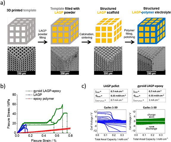
Figure 3. Experimental results showing that increasing the fracture toughness of a solid electrolyte increases critical current density on plating. Schematic and SEM images detailing the preparation of structured ceramics are shown in (a). Hybrid ceramics show a greater fracture toughness (b) and so do not fail at a current density of 0.7 mA cm−2 whereas non-hybrid ceramics mechanically fracture at this current density. Figure reprinted with permission from [11]. Copyright Energy & Environmental Science.
Download figure:
Standard image High-resolution image2.4. Concluding remarks
Increasing critical current densities is important if we are to achieve power densities for solid-state batteries that are competitive with Li-ion cells. While progress has been made in terms of understanding some of the factors limiting critical current densities, notably the critical stripping current, the challenge of understanding dendrite penetration into solid electrolytes remains. An improved fundamental understanding of the ceramic/lithium interface is needed to enable solid-state batteries capable of sufficient current densities for commercialisation.
Acknowledgments
The authors would like to acknowledge the financial support of the ISCF Faraday Challenge project SOLBAT [grant No. FIRG007], and the Henry Royce Institute (through UK Engineering and Physical Science Research Council grant EP/R010145/1) for capital equipment.
3. Mechanical modelling of dendrite and void formation
Norman Fleck1,3, Vikram Deshpande1 and Alan Cocks2
1 Department of Engineering, University of Cambridge, Cambridge CB2 1PZ, United Kingdom
2 Department of Engineering Science, University of Oxford, Oxford OX1 3PJ, United Kingdom
3 The Faraday Institution, Quad One, Harwell Campus, OX11 0RA, United Kingdom
3.1. Status
Ceramic electrolytes have potential in the field of solid-state batteries (SSBs). When combined with Lithium (Li) anodes, they can deliver enhanced safety and higher energy densities compared to liquid electrolyte Li-ion batteries. However, the charging of such cells at current densities greater than a critical value leads to Li-filled fissures, commonly referred to as 'dendrites'. These dendrites nucleate and grow from the Li-metal electrode across the electrolyte, and thereby short-circuit the cell. Dendrites can adopt a range of morphologies, from a 3D 'mossy' form, thought to originate from the filling of interconnected porosity, to planar fingers resulting in the fracture of the ceramic electrolyte. Characteristic features of this failure mechanism are now established through the recent work of Bruce and co-workers [4], and Sakamoto and co-workers [15]. For example: (i) the critical current required to short the cell increases with decreasing resistance to the flux of Li+ ions across the electrolyte/Li-metal electrode interface, and (ii) continued charging/discharging of the cell results in the formation of voids in the Li-metal at the interface with the electrolyte. Dendrites initiate and grow in the vicinity of the voids (see figure 4). The application of an external pressure shrinks the voids (by diffusional flow and power law creep), thereby elevating the critical current for dendrite formation within the electrolyte. A mechanistic understanding of these observations, in terms of both dendrite growth and void growth, remain elusive.
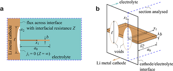
Figure 4. (a) Sketch of the 2D problem of a dendrite of length a0 emanating at right angles from the centre of a void of size l in the electrode along the electrolyte interface. The void is modelled as a patch of size l. (b) 3D sketch of the void along the interface, showing the electrical connection of the dendrite to the electrode.
Download figure:
Standard image High-resolution image3.2. Current and future challenges
Robust and rigorous models can provide insights into mitigation against failure modes in solid electrolyte cells, such as dendrite growth from voided-interfaces. However, such models are not yet available. A number of approximate calculations have been performed to predict the growth of a pre-existing dendrite. The usual assumption is that the dendrite behaves as a Li-filled crack, with crack advance driven mechanically by pressurised Li within the crack. This approach is problematic, however, as the magnitude of the pressure required to attain the fracture toughness of the electrolyte is sufficiently high that the Li will instead leak into the soft Li electrode, thereby relieving this pressure. Moreover, there is insufficient electrical energy available to provide the elastic energy in the electrolyte associated with a pressurized crack. Recently, it has been suggested that dendrites grow as parallel sided dislocation-like features, as this mode does not entail pressurisation of the dendrite at its mouth, and requires much less elastic energy storage within the stiff electrolyte. However, these calculations suggest that such dendrites are unlikely to grow without an electrical field concentration, as generated by the presence of voids in the Li along the electrode/electrolyte interface [16]. There is, therefore, a major challenge to understanding the reasons why voids develop within an Li electrode. Preliminary models suggest that void growth occurs during the stripping of Li from the electrode, and is associated with a high concentration of Li flux from the electrode into the electrolyte at the periphery of the void. However, the fundamental mechanism for this flux concentration needs to be understood, along the following lines: the product of ionic interface resistance Z and ionic conductivity ϰ within the electrolyte defines a characteristic material length scale, and the degree to which Li flux is concentrated at the periphery of the void increases with the ratio of void dimension to this length scale Zϰ. Typically, Zϰ ≈ 20 µm, and it is unclear why small voids (smaller than, say, 100 µm) are able to concentrate the Li flux and thereby induce void growth. While useful data and observations on macro-scale phenomena in such cells do exist, model validation and mechanistic understanding also requires high resolution observations. For example, observation of the initiation and growth of a dendrite in order to give insights into the mechanism of dendrite formation is challenging. The thickness of dendrites is on the order of 20 nm, so high-resolution methods are required. Such observations will help to resolve whether dendrites grow with a crack-like opening, or in a dislocation mode with parallel-sided flanks. Again, while there is a well-documented link between the measured value of interface ionic resistance Z (between Li electrode and the adjacent ceramic electrolyte) and the critical current density for dendrite formation, these Z values are averages over the entirety of electrode/electrolyte interfaces. It is clear that large variations in the flux along the interface can trigger void growth, but there is little information on the spatial distribution of Z along the interface. Do variations in Z along the interface explain the void growth observations?
3.3. Advances in science and technology to meet challenges
There is a clear need for increasing the resolution of x-ray computed tomography (XCT) methods and related microscopy, in order to resolve dendrites, and to follow their growth. The availability of such data for liquid electrolytes has spurred significant advances in understanding and model development. In parallel, there is an urgent need for the development of theoretical frameworks for modelling the processes within solid-state cells. In such cells there is a strong coupling between mechanical loading (e.g. the elastic straining of the electrolyte due to dendrite formation or power-law creep of the Li-metal electrode) and associated electrochemical processes. These couplings often render inappropriate a number of commonly used assumptions in the theory of electrochemical systems. For example, the Butler-Volmer equation is commonly expressed in terms of current density as a function of voltage jump across an interface. More accurately, the current density is a function of jump in electrochemical potential across an interface, and this jump in potential is related to jumps in stress state, strain state, vacancy content and so on, in addition to the jump in voltage. The development of appropriate new modelling approaches is expected to shed light onto some of the puzzles alluded to above.
3.4. Concluding remarks
SSBs offer significant benefits in terms of energy density and power density, but this can only be achieved when potential failure modes are eliminated. There is a need to develop quantitative models at the meso-scale that are consistent with the governing field equations. Such models require experimental validation, but have the potential to vector material developments by explaining the relationship between material properties and failure mechanisms. These problems are challenging, and require a grounding in both electrochemistry and solid mechanics.
Acknowledgments
This work was supported by the Faraday Institution [SOLBAT, grant No. FIRG007] and by the ERC project 'Multilat'. The authors are grateful to Peter Bruce, Clare Grey and Jeff Sakamoto for helpful discussions.
4. Mechanical properties of metallic lithium
Ed Darnbrough and David Armstrong
Department of Materials, University of Oxford, Oxford OX1 3PH, United Kingdom
The Faraday Institution, Quad One, Harwell Campus, OX11 0RA, United Kingdom
4.1. Status
The leap forward in energy density facilitated by solid-state batteries (SSBs) is thanks to the use of a metallic anode significantly increasing the number of possible charge carriers [17]. This gives rise to new challenges, as the historic lack of any structural application means that the mechanical properties of alkali metals are under-investigated. Recent work on metal anode systems for SSBs has demonstrated that applying an external pressure to cells has a beneficial effect [4, 5]. This is seen to reduce the formation of pernicious 'dendrites'. The cause of 'dendrites' is currently an unexplained phenomenon, where the 'soft' lithium penetrates the 'hard' ceramic electrolyte [18]. These issues have sparked recent interest to fully mechanically characterise metallic lithium. This has led to a number of recent papers looking to measure the tensile, compressive and time-dependent mechanical properties of lithium, with a spread of results [12, 19, 20]. However, this field is still in its infancy and requires more work, as developing a full understanding of the mechanisms behind the mechanical properties of lithium metal are a missing keystone in the new battery revolution.
4.2. Current and future challenges
4.2.1. Sample preparation
Li-metal is air sensitive, readily forming compounds with oxygen, water, carbon dioxide, and nitrogen. This means that the material must be kept in an atmosphere exempt from these common gases, and a chemical or mechanical method is required to remove any residual surface layers to create the smooth surface required for most characterisation techniques. The low hardness of Li-metal requires mechanical polishing via abrasion in order to remove any material causes of significant plastic deformation and geometric change to its surface. Chemical cleaning for standard metals utilises acids to etch, which would cause a violent reaction with lithium. The final alternative for surface preparation is through the use of an ion beam; however, this can lead to local heating/melting and suspected implantation of these ions into the material. There are concerns that legacy work on lithium (especially where the handling of samples was not reported) maybe affected by the formation of passivation layers, leading to uncertainties in this data.
4.2.2. Experimental testing
Standard mechanical testing requires high precision test rigs which combat compliance, thermal drift, and noise in displacement readings by being large (∼ 2 m tall). For air sensitive materials, smaller test set-ups, hosted within gloveboxes, are required, leading to a compromise in the reliability of the resulting data. Cutting or forming lithium test specimens can introduce large numbers of dislocations, which in turn lead to work hardening. The low yield stress relative to Young's modulus means that only a strain between 0.002 5% and 0.01% (dependent on orientation) is needed to lead to plasticity. These issues combine to make measuring a 'yield stress' in pure lithium difficult. This orientation dependence comes from the anisotropy of elastic moduli in the BCC crystal structure of Li-metal. This is significant in lithium due to its low melting point, leading to large grain microstructures in room temperature samples. The effect of texture is the suspected root cause of the variability in reported elastic properties [19, 20].
4.2.3. Understanding
The effect of low stress plasticity and the ease of plastic flow needs to be understood for localisation of plasticity relative to the application of force. It is possible that weak material at the surface will accommodate applied stress through plasticity, leading to the bulk of the material experiencing little to no stress. Additionally, the low melting point of lithium means that room temperature (∼ 0.6Tm) creep is likely, causing time-dependent plasticity. How the creep mechanism is affected by strain rate, temperature, and crystallography is still unknown, with little mechanistic understanding reported. All of this work is geared toward investigating Li-metal in isolation, but its true impact will become evident when observing the role of mechanical properties in a working cell, which will bring more challenges, both experimentally and cognitively.
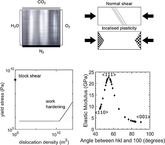
Figure 5. Challenges: Li-metal reacts to form a bi-product with atmospheric gases - understanding the localisation of plasticity, the role of work hardening, and the anisotropy of the elastic modulus.
Download figure:
Standard image High-resolution image4.3. Advances in science and technology to meet challenges
The ubiquity of gloveboxes of all shapes and sizes has allowed for an increased number of tabletop mechanical testing techniques to be utilised for Li-metal. These small-scale tensile and compression tests, combined with optical monitoring, have provided an enhanced insight into how lithium acts under stress [19, 20]. This has increased the amount of mechanical data on Li-metal,; however, some information on microstructure, which would allow for a comparison of the available literature, is still lacking, due to the anisotropy discussed above. Turning to smaller scale testing, using nanoindentation and pillar compression allows for the characterisation of pseudo single crystals, thus avoiding the effect of any preferential texture on recorded data [12]. The downside of these tests lies in controlling the volume of tested material, as this is unconstrained, leading to some questions relating to plasticity being left unanswered. The use of gallium and argon plasma focused ion beams (FIBs) in the future could allow for the testing of known volumes of material via cantilever or tensile tests on the microscopic scale. However, there are questions about the effect of such ions beams on materials' physical and electronic properties. This requires the joint technologies of cutting-edge microscopy/lithography, and the ability to perform such work at cryogenic temperatures so as to avoid the local melting referred to when discussing ion surface preparation. Further advancements could be made in conducting tests in situ using scanning electron microscopy (SEM), transmission electron microscopy (TEM), and x-ray diffraction (XRD) to characterise the plastic changes crystallographically in real time, which would conbtribute to a greater understanding of stress/strain evolution. Critical to this understanding is the interplay between dislocation nucleation and dislocation motion, the latter having huge consequences for the time-dependent plasticity referred to as creep. Comprehensive mechanical test data will help to unpick the fundamental character of Li-metal under stress, allowing for great advances in the modelling of the materials, and would also complement the wealth of knowledge on the other aspects of Li-metal. The pinnacle of understanding could be reached by realising in-operando tests allowing direct observation of how the mechanical properties of lithium change as it acts in battery cells.
4.4. Concluding remarks
Advancement in lithium mechanical property characterisation has not occurred in an intellectual vacuum; it has come as a necessity. As such, rapid advancements were made in terms of working with air-sensitive materials based on the current knowledge of the battery community; however, the next step change will be driven by the application of metallurgists and material scientists who have the language and the tools to understand the complex elastic and plastic nature of Li-metal. An understanding and application of the deformation modes of Li-metal will assist modellers, designers, and builders of high energy density battery technology far into the future.
Acknowledgments
The authors gratefully acknowledge the support of the ISCF Faraday Challenge project SOLBAT [grant No. FIRG007].
5. Wetting behaviour of Li-metal
Peiyu Chen and Martin R Castell
Department of Materials, University of Oxford, Oxford OX1 3PH, United Kingdom
The Faraday Institution, Quad One, Harwell Campus, OX11 0RA, United Kingdom
5.1. Status
In current commercial designs of Li-ion batteries, graphite anodes are almost at the limit of their theoretical specific capacity (372 mA h g−1) [21]. Li-metal anodes (LMAs) are considered the most promising alternative for future cells because of their high theoretical specific capacity (3860 mA g−1), low electrochemical redox potential (−3.04 V vs the standard hydrogen electrode), and low density (0.53 g cm−3)[22]. A major hurdle to be overcome for the successful commercial application of LMAs is the formation of needle-like Li dendrites during charging/discharging cycles. Once the Li dendrites detach from the bulk LMA, they become 'dead Li', i.e. they are no longer electrochemically active, reducing the Coulombic efficiency of the cell [23]. More crucially, sharp dendrites can penetrate the separator, creating a short circuit with associated overheating and even an explosion risk [24]. Solid electrolytes (SEs) have been shown to mechanically suppress dendrite growth [25] and are more inert towards metallic Li than their liquid counterparts. However, dendrites are still observed to grow from grain boundaries and other interfacial defects in SEs [26]. Another issue restricting the application of SEs is their high interfacial resistance; therefore, a high pressure is required to maintain close contact with the electrodes. Thus, an improved understanding of the binding or wetting between the LMA and the SE is also essential to the development of lower-resistance interfaces. Two possible scenarios are shown schematically in figure 6, which also includes the copper (Cu) current collector at the anode [27]. Ideally, we would like complete wetting to occur between both SE/Li and Li/Cu (figure 6(a)), to maximise the electrical contact. However, in practice partial wetting is likely, where Li grows into three-dimensional (3D) islands between the SE and the Cu (figure 6(b)). The aim of Li wetting studies is to find processing parameters that will allow the current collector, the LMA, the SE, and any interphases between these materials to have sufficiently low interfacial energies to enable thermodynamically favourable conditions for the formation of flat interfaces. This will hopefully act as a method for preventing Li dendrite formation, and increasing the ionic conductivity between the anode and the SE. The strategy is to investigate all these interfaces individually by forming them under ultrahigh vacuum (UHV) conditions, and to extract interfacial energies from these studies.
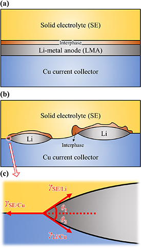
Figure 6. (a), (b) Schematic drawings of two possible interactions between the solid electrolyte (SE), Li-metal anode (LMA), and Cu current collector, and (c) the interfacial energies at a triple junction.
Download figure:
Standard image High-resolution image5.2. Current and future challenges
The degree of Li wetting is determined by the interfacial energies between the three materials, i.e.  ,
, , and
, and  , as labelled in red in figure 6(c). At the triple junction, the three interfacial energies are related by geometry at equilibrium:

Therefore, to achieve complete wetting (figure 6(a)), the θ angles have to be zero, and the following relationship needs to be satisfied:

The value of  can be worked out by depositing Li on the SE material and observing the behaviour of Li island growth. The other two interfacial energies,
  and
and  , can be found in a similar way, by depositing the relevant materials on top of each other. However, this type of physical vapour deposition (PVD) study of Li is rare [28]. Although Li wetting on ceramics has not been studied before, there are many reports on the interaction between other metals and ceramic substrates. For a single crystal ceramic substrate, the main mechanism by which it influences the morphology of the supported metal islands is via their interfacial energy (
 ) and the substrate surface energy (
 ). For example, figure 7 shows five different degrees of wetting of a supported platinum (Pt) crystal, from no wetting (first crystal), to partial wetting (middle three), to complete wetting (last crystal) [29]. Higher values of
  and lower values of
  encourage the crystal to wet. More interestingly, two-dimensional (2D) wetted islands of gold were also reported to coexist with gold crystals on various oxide substrates. For example, they are stabilised by the (2 × 1)-reconstructed (001) surface of strontium titanate (SrTiO3) [30]. Based on the above, for LMAs, the research question is to develop a fundamental understanding of the interface between Li and the electrolyte ceramic material. This will also include a study of the chemically distinct interphases that form at their interface.
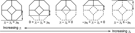
Figure 7. Winterbottom construction for a supported Pt crystal with various degrees of wetting. The grey line represents the substrate. Higher  leads to less wetting; higher
  leads to more wetting. Adapted with permission from [29].
Download figure:
Standard image High-resolution image5.3. Advances in science and technology to meet the challenges
The study of the SE/Li interface requires a combination of characterisation techniques. As an example, Li can be deposited by PVD in UHV onto a ceramic substrate. As a starting point, a model ceramic oxide can be used, whose surface structure must be well known, e.g. Nb-doped single crystals of SrTiO3 [30]. The wetting behaviour of Li can then be established at the atomic and microstructural length scales, by scanning tunnelling microscopy (STM) and scanning electron microscopy (SEM), respectively. The reactivity of Li with the substrate can be investigated using x-ray photoelectron spectroscopy (XPS), which provides information on the chemical environment of the buried Li-metal at the interface with the ceramic. STM results obtained from a similar system, gold on SrTiO3, clearly illustrate the morphologies of both 2D and 3D metallic islands [30]. The shapes of 3D nanocrystals can be measured accurately and used to calculate the interfacial energy  , according to the Winterbottom construction (figure 7). In reference [30], a square pattern of spots was also obtained on 2D gold islands under STM, possibly resulting from the frustrated commensurate epitaxy between gold and the substrate. These all demonstrate the potential of STM in investigating the SE/Li system. Similarly, STM characterisation of Cu deposited on SrTiO3, and Li deposited on Cu will provide values of
  and
and  , which together will establish the Li wetting scenario in the SrTiO3/Li/Cu system. Once the model experiments have been performed, the Li interface with technologically pertinent solid electrolyte and cathode materials can be studied. These include Li7La3Zr2O12 (LLZO), LiMn2O4 (LMO), LiCoO2 (LCO), LiNi0.8Co0.15Al0.05O2 (NCA), etc. An additional challenge is that for these insulating oxides to be characterised by STM, they need to be prepared in the form of ultra-thin-films as epitaxial overlayers on a conducting substrate, e.g. on Au(111). This can be achieved either through UHV evaporation and oxidation of the elemental materials, or via pulsed laser deposition of the target oxide. Again, interfacial energies (
 ,
,  , and
, and  ) can be obtained to study Li wetting. Special attention should also be paid to the effects of ceramic surface defects on the Li binding, which may play a role in Li dendrite propagation.
5.4. Concluding remarks
Ultimately, the techniques described above (STM, SEM, and XPS) will provide valuable insights into the fundamental processes taking place at the Li/electrolyte interface. In particular, the interfacial energies involved in the SE/Li/Cu setup will allow us to work out the degree of Li wetting and, in turn, identify SE materials with optimised electrode/electrolyte binding. In addition, study of the SE/Li interfacial processes can shed light on the origin and propagation of Li dendrites. We can then derive novel strategies to create more resilient ion-conductive ceramics for the best possible performance of a solid-state battery. The successful implementation of LMAs with SEs is a critical step for electric vehicle improvement, and will result in safer cars with batteries superior in performance to current Li-ion batteries.
Acknowledgments
This research is funded by the Faraday Institute (SOLBAT project). The authors would like to thank Chris Spencer (JEOL U.K.) for technical support.
6. Electron microscopy: imaging Li-metal
Weixin Song1,2, Emanuela Liberti1 and Peter D Nellist1,2
1 Department of Materials, University of Oxford, Oxford OX1 3PH, United Kingdom
2 The Faraday Institution, Quad One, Harwell Campus, OX11 0RA, United Kingdom
6.1. Status
Lithium (Li) is the key element in Li-ion batteries (LIBs) and is thus contained in the cathodes and (solid/liquid) electrolyte; there is significant potential for Li-metal to be used as a high-capacity anode for next-generation batteries. Techniques to image Li in battery materials therefore form an important part of the portfolio of battery material characterisation methods. In particular, imaging with a high spatial resolution will allow a deeper understanding of Li function in battery materials. Here, we discuss techniques of electron microscopy currently being developed and applied to study these materials. Early work applied transmission electron microscopy (TEM) to the study of the motion and interaction of dislocations in Li-metal, using the dark-field mode [31]. More recently, imaging has been used to understand the mechanical interactions at the electrode/electrolyte interface in a battery [12]. The imaging of Li can give an insight into the electrochemical reaction, leading to a greater understanding of its degradation mechanisms. In charged cathode materials, transition metal movement into the Li locations results in cation disorder degradation of the cathode [32]. Imaging of Li and transition metals in cathode materials reveals the new structures formed, and the defects responsible for the reduced reversibility. At the anode interface, Li dendrites grow during cycling and lead to safety issues. Scanning electron microscope (SEM) imaging of the dendrites has helped to elucidate the formation mechanism under different plating/stripping conditions [4], and validates the strategies to mitigate dendrite growth. Solid electrolytes (SEs) contain disordered structures and vacancies to ensure Li conduction. Scanning TEM (STEM) imaging of Li in SE has revealed the atomic arrangement of the existing Li-rich and Li-poor phases and vacancy clusters [33]. Li aggregation close to the vacancies has been suggested to enhance crystal distortion, and to affect the Li-ion migration pathways [33]. The solid electrolyte interphase (SEI) is a chemically-formed passivating film between electrolytes and electrode, critical to reversible battery operation. Imaging of Li in SEI has atomically resolved the Li arrangement at the bottom of the SEI layer, as well as Li-based nanocrystals in the film. The atomic structures of both the nanocrystals and Li dendrite nanowires on the layer illustrate tuneable SEI configurations arising from the change of electrolytes [34].
6.2. Current and future challenges
Direct imaging of the chemically reactive and beam sensitive Li-metal is challenging. Li is a light element, so the high-energy electrons used in TEM imaging are scattered weakly, and the primary effect is a small phase shift of the transmitted electron wave. The high-angle annular dark field (HAADF) images commonly used in STEM for atomic resolution imaging give contrast approximately as the square of Z, and so are insensitive to light elements, such as Li. Furthermore, the low contrast of Li tends to render it unobservable when in proximity to the heavier transition metals because the strong signal of heavy elements may swamp the signal from light elements. Coherent bright field (BF) STEM images and high-resolution TEM (HRTEM) images provide phase contrast of both light and heavy elements, but have restricted requirements regarding specimen thickness. Annular bright field (ABF) STEM images make use of the annular detector located in the BF region, and can simultaneously visualize both light and heavy elements over a wide range of specimen thickness. ABF images show a combination of weak Z-contrast and phase contrast imaging; however, the ABF setup requires well-aligned microscope optics and is challenging to use for quantitative measurements. Damageto Li is due to the high-energy electrons and radiation sensitivity of samples. The main damage mechanisms include knock-on, radiolysis, and possible sample heating. Metallic bonded Li-metal is rich in free electrons, and radiolysis can be rapidly quenched [36]. The low mass of Li and the low melting point of Li-metal make Li-metal particularly susceptible to damage from electron sputtering (knock-on) and heating. Beam damage to the Li-metal reduces the achievable resolution in imaging, and reduces the detectability of Li using spectroscopy. Electron energy loss spectroscopy (EELS) is challenging because of the small inelastic cross section (low signal) and low energy of Li K-edge. To increase the signal-to-noise ratio in EELS, a higher electron dose is needed, resulting in higher degree of damage. The Li K-edge is close to the plasmon region in the EELS spectrum, which can mask the Li K-edge. In thick specimens, multiple scattering is prevalent, and will further obscure the edge [36]. Li also has a low x-ray yield, resulting in poor detection efficiency for energy-dispersive x-ray spectroscopy (EDX). Characterizing x-rays of Li and mapping Li distribution can be challenging.
6.3. Advances in science and technology to meet challenges
Although imaging of Li has proved challenging, recent advances in electron microscope design, specimen-transfer holders, and imaging methods are now enabling reliable characterization of Li-metal. Radiation damage to the sample is highly dependent on the beam energy, and optimal selection of the accelerating voltage in the microscope can mitigate beam effects. Modern (S)TEM instruments can be operated over a wide range of accelerating voltages, and voltages below 100 kV can reduce the knock-on damage on Li [34]. Li and most Li-containing battery materials are air-sensitive; therefore, to avoid air contamination, air-free sample transfer to the microscope is needed. Vacuum-transfer holders are now available to mount the specimen and transfer it from an argon-flowing glove box to the microscope. Low electron-dose experimental conditions are necessary to lower the radiation damage. However, imaging at high-spatial resolution requires a relatively high electron energy and high dose rate, inevitably leading to increased sputtering and heating damage. Because of this, cooling the sample using a cryo-transfer holder has proven helpful in reducing beam damage to the Li, and preserving atomic resolution (figure 8) [35, 36]. It has also been suggested that the ice layer during cryogenic processing may protect the Li sample from air. Li K-edge EELS and mapping have also been used to analyse the composition of Li dendrites and electrochemically-deposited Li-metal in cryo-STEM [37]. Electron ptychography is a method for reconstructing the phase information from the complex specimen exit wave function, and has been shown to be a dose-efficient method. This technique makes use of direct electron detectors with a very high detection efficiency. High-efficiency phase reconstruction by ptychography allows the reduction of beam currents down to the sub-picoampere range, along with the post-acquisition correction of residual aberrations. Ptychographic phase reconstruction of the charged Li-rich cathode has demonstrated sensitivity to heavy and light elements simultaneously, with minimum beam damage [38] (figure 9).
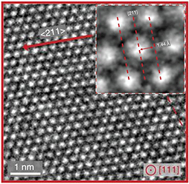
Figure 8. HRTEM image of Li-metal along a [111] zone axis obtained using cryo-electron microscopy [34]. Electron dose ≈ 30 000 eÅ−2. Image reproduced from reference [35] with permission from Elsevier, Copyright (2018).
Download figure:
Standard image High-resolution image
Figure 9. ABF-STEM micrographs (left) and ptychography reconstructed phase image (right) of a charged Li1.2Mn0.6Ni0.2O2 particle along the [010] direction taken with beam currents of (a) 6, (b) 2, and (c) 0.4 pA. Grayscale: (a) 0 to 0.98, (b) 0 to 1.48, and (c) 0 to 1.70 rad. Reproduced from reference [38]. with permission from American Chemical Society, Copyright (2018).
Download figure:
Standard image High-resolution image6.4. Concluding remarks
High spatial-resolution imaging of Li-metal is of increasing importance in terms of battery function and degradation, for example through the potential of Li-metal as a high-energy battery anode, despite the fact that the problems of dendrite growth and low coulombic efficiency are still unresolved. Imaging and spectroscopy of Li-metal are critical to the understanding of its physicochemical properties and the interface that forms with the electrolyte. Recent progress in direct electron detectors and data processing has greatly improved the dose efficiency and lowered the level of beam damage in imaging. This is a rapidly developing area, and forthcoming powerful detectors will create opportunities for further imaging and spectroscopy of Li-metal. A growing number of new capabilities (e.g. cryo-TEM) and low-dose imaging methods are being developed for biological materials, the concepts of which might be transferrable to the study of Li-metal, but trials will be needed to validate their applicability to battery materials. The results of imaging and spectroscopy of Li-metal will provide new information about Li-metal in batteries, and future characterization will be of great assistance in the fundamental study of Li-metal chemistry.
Acknowledgments
Support is gratefully acknowledged from the EPSRC (EP/K040375/1 'South of England Analytical Electron Microscope'), the Henry Royce Institute for Advanced Materials (EP/R00661X/1, EP/S019367/1, EP/R010145/1) and the Faraday Institution (FIRG007, FIRG008). We acknowledge the electron Physical Sciences Imaging Centre (No. MG22479) at the Diamond Light Source, UK, for access and support.
7. Electro-chemo-mechanics in solid electrolytes
Guanchen Li and Charles W Monroe
Department of Engineering Science, University of Oxford, Oxford OX1 3PJ, United Kingdom
The Faraday Institution, Quad One, Harwell Campus, OX11 0RA, United Kingdom
7.1. Status
The development of commercial electric vehicles requires safer batteries capable of achieving a specific energy of 235 W h kg−1 and an energy density of 500 W h l−1 at cell level, with a reduction of pack cost to $125/kWh [39]. Solid-state batteries using solid electrolytes are a next-generation system that may meet these requirements. Early research on solid electrolytes originated more than 40 years ago, with studies focused on the application of beta-alumina as a sodium-ion conductor, and on space-charge models to rationalize Donnan potentials in ionically conductive single-ion conductors [40]. Inorganic solid electrolytes with sufficiently high room-temperature conductivity for lithium-ion battery applications have only been widely available for the past decade [41, 42]. It is widely believed that these solid electrolytes could naturally mitigate many problems that place limitations on today's liquid-electrolyte lithium-ion batteries [43]. Solid electrolytes are generally non-toxic and not flammable, properties that would significantly improve battery safety. Solid ion conductors have exhibited a much wider viable range of working temperatures, and do not freeze at low temperatures or vaporize at high temperatures. Generally, solid electrolytes are single-ion conductors, which eliminates the voltage losses occurring due to concentration polarization when liquid electrolytes are operated at high power. The most popular examples are ceramics or ceramic glasses, either oxides or sulphides. Because they do not suffer from concentration polarization in the electrolyte domain, solid-state batteries can in principle include much thicker composite electrodes, which might enhance their energy density. Moreover, the huge stiffness of solid oxide or sulphide separator materials can suppress the nucleation of dendrites due to interfacial morphological instability at high currents. This stiffness advantage potentially enables the use of lithium-metal anodes. Solid electrolytes can block degradation mechanisms that accompany the interdiffusion of species between the electrodes of a battery: solid oxides may enable lithium/oxygen technology by preventing oxygen crossover to the lithium anode, and solid sulphides may resolve the issue of polysulphide shuttling in lithium/sulphur systems. In liquid-based batteries, the electro-chemo-mechanics of electrode materials has received substantial attention. It is already known that volume change during lithium intercalation causes particle or SEI cracking, both regarded as crucial sources of degradation in today's batteries. The growing interest in solid-state batteries has further fuelled the community's interest in solid-state electro-chemo-mechanics.
7.2. Current and future challenges
Stress accumulates in solid electrolytes. Interactions among electrical, chemical, and mechanical phenomena, especially near solid/solid interfaces, account for most of the major barriers to viable solid-state batteries (figure 10). Dendrite formation at the metal/electrolyte interface limits power density [26]. Mechanical failure - delamination, cracking, etc. - at the cathode-particle/electrolyte interface leads to active-material loss and consequent capacity fade [44].

Figure 10. (a) Lithium filament formed in Li7La3Zr2O12 garnet and its microstructure [26]. Reprinted from Electrochimica Acta, 223, Cheng et al, 85–91, Copyright (2017), with permission from Elsevier. (b) Contact loss in NCM-LiPS composite electrodes and (c) details at the NCM-LiPS interface [44]. Reprinted with permission from Chemistry of Materials, 29 (13), 5574-5582, Koerver et al, Copyright (2017), American Chemical Society.
Download figure:
Standard image High-resolution imageStiff solid electrolytes support stable cycling performance when currents are sufficiently low, while dendrites have been observed to form when cells are cycled above a 'critical current'. The mechanism of dendrite formation in ceramic electrolytes is still unclear, since solid electrolytes suppress both carrier polarization and morphological instability, which are the key reasons for dendrite nucleation in liquids [25]. Early experiments on sodium beta-alumina suggested that there are two modes of dendrite growth in solids: crack propagation from the edge, and bulk plating related to electron conduction [2]. Both modes have been observed in solid lithium-ion conductors. Griffith's cracking model implies that the propagation of pre-existing microcracks at the edge of an electrolyte will unavoidably lead to electrolyte failure [8]. Thus, research should focus on designing systems that impede dendrite nucleation altogether.
Cavities can form at the metal/solid electrolyte interface when lithium is being stripped, a problem that highlights the importance of transport in the metal, as well as in the electrolyte. The loss of interfacial contact during stripping decreases the critical current in subsequent plating steps. Application of a uniaxial stress to the electrode stack can slow cavity formation, perhaps by speeding up lithium diffusion or flow within the metal. The mechanical properties of lithium - especially those describing creep and plastic deformation at the nanoscale - are sparsely measured, a factor that has impeded the theoretical analysis of stripping critical currents at the metal/solid electrolyte interface. Volume expansion in intercalation materials is probably the most significant barrier to solid-state batteries. Solid electrolytes are generally stiff, and some are brittle. Such materials have a limited ability to accommodate the strain caused by the intercalation process. Deformation may not be purely elastic, so particles may not recover their initial shapes during delithiation, resulting in cracking or interfacial delamination. Furthermore, some solid electrolytes require coatings to remain stable in contact with intercalation materials, another factor that makes the chemo-mechanical analysis of composite electrodes more complex. Stress can affect open-circuit potentials, and therefore may impact interfacial reaction rates and lead to stress diffusion of lithium within particles, both factors affecting power capability. The complex interaction mechanics in composite, dual-solid cathodes are inevitably significant, and are still not well described by models.
7.3. Advances in science and technology to meet challenges
Understanding the impact of mechanical state on interfacial electrochemistry is crucial to improving solid-state battery performance. Interfaces exhibit a complex coupling among space-charge effects, electrochemical reactions, and multicarrier transport phenomena. State-of-the-art solid electrolytes exhibit critical currents around 0.1 mA cm−2 at room temperatures. However, as described in section two, a critical current density of 5 mA cm−2 is the desired target for practical application. Experiments have illustrated the central role of metal/electrolyte interfacial impedance and interfacial contact in the determination of critical currents. Many interfacial treatments have been exploited to reduce interfacial resistance, including heat treatment, alloy coating, the addition of liquid additives, etc. The microstructure of solid electrolytes, i.e. porosity and grain size, is also shown to impact greatly on power performance. The observation of bulk plating requires a better understanding of how solid electrolytes may contain and conduct free electrons. A recent model by the authors of a study on dendrite nucleation and bulk plating has shown that large mechanical forces can arise as a consequence of the dielectric properties of solid electrolytes and interfaces, which correlate with critical currents [45]. Dielectric properties have been largely ignored to date, and merit further study.
Solid-state batteries with thick cathodes have been built and cycled. It has been suggested that a proper volume ratio of electronic conductive active materials and ionic conductive solid electrolytes is required to provide good percolating conductive paths for both ions and electrons. Volume expansion induced by intercalation needs to be managed carefully to minimize the contact loss or mechanical failure of particles. Smaller particles are generally favoured to mitigate cracking. Theoretical study suggests that delamination may be suppressed by properly matching the mechanical properties of solid electrolytes and intercalation compounds.
7.4. Concluding remarks
The coupling of mechanics and electrochemistry in solid electrolytes and interfaces is critical to the performance of solid-state batteries. Phenomenological theories that elucidate solid electrolyte failure (especially the initiation stages of such failure) and degradation are desired to guide battery design. Despite the fact that working current densities have been significantly enhanced through the use of high-quality, dense solid electrolytes with various interfacial treatments, the origins of failure modes are still unclear. On the cathode side, although many electrode designs have achieved acceptable cycling performance, both theoretical and experimental efforts are still needed to reduce the susceptibility to mechanical degradation.
Acknowledgments
This work was supported by the Faraday Institution, within the SOLBAT challenge, grant Nos. FIRG003 and FIRG007, the UK EPSRC, under grant No. EP/P003532/1, and the ISCF Materials Research Hub for Energy Conversion, Capture, and Storage (M-RHEX), grant No. EP/R023581/1.
8. Characterisation of electrode-electrolyte interfaces in solid-state batteries
Yundong Zhou and Laurence J Hardwick
Stephenson Institute for Renewable Energy, Department of Chemistry, University of Liverpool, Liverpool L69 7ZD, United Kingdom
The Faraday Institution, Quad One, Harwell Campus, OX11 0RA, United Kingdom
8.1. Status
Within solid-state batteries (SSBs), numerous interfaces exist between electrode active materials and the solid electrolyte. For the practical application of an SSB, minimal impedances between interfacial layers are required. The buried nature of these interfaces presents certain challenges in order to characterise them with traditional surface characterisation techniques, whether ex-situ, in-situ or operando. To design solid-state batteries which optimise specific energy and longer life, it is important to understand the processes happening at the interface between the solid electrolytes and cathodes, and to adopt rational approaches to solve the problems causing cell degradation. Thus, the development and exploitation of new and existing methods of characterising the interface within solid-state batteries, at both anode and cathode, is critically important for guiding future development strategies.
The origin of cell failure is due to both chemical and electrochemical interfacial instability, as well as to mechanical robustness, where fracture will result in loss of contact between electrode and electrolyte [47]. As in the case of liquid electrolytes, solid-state electrolytes have an electrochemical stability window outside of the potential range of the majority of anodes and cathodes; thus, solid electrolyte interphase layers will form upon both electrodes, chemically and/or electrochemically, as shown in figure 11 [46]. The solid-solid contact between the solid electrolytes and cathodes can be lost due to volume change in the cathodes during cycling. Lithium (Li) metal creeping behaviour is also influenced by void formation at the interface between Li-metal and solid electrolytes [4]. Understanding the complex nature and interplay of these various buried interfacial regions as they evolve as a function of time, rate of charge/discharge and potential is a significant challenge, requiring a host of advanced characterisation techniques. Much work has already been carried out to develop novel characterisation methods and tools for the study of solid electrolyte-electrode interfaces, both ex-situ and in-situ/operando within SSBs, as summarised in figure 12, and within recent review articles [47, 48]. Below, recent progress in interface characterisation will be highlighted, and future challenges and strategies discussed.

Figure 11. Schematic illustration of open-circuit energy diagram for a solid-state Li-Solid Electrolyte-LixMyO2 battery. Reprinted with permission from reference [46].
Download figure:
Standard image High-resolution image
Figure 12. Schematic illustration of utilised ex-situ and in-situ/operando characterisation techniques for the interfaces within solid-state batteries. EIS, XPS, STEM, EELS, MRI, TEM, NMR stand for electrochemical impedance spectroscopy, x-ray photoelectron spectroscopy, scanning transmission electron microscopy, electron energy loss spectroscopy, magnetic resonance imaging, transmission electron microscopy, and nuclear magnetic resonance, respectively.
Download figure:
Standard image High-resolution image8.2. Current and future challenges
Compared to traditional lithium-ion cells containing liquid electrolytes, SSBs present new challenges regarding interfacial characterisation methods and tools. The surface/interface areas between the electrodes and electrolytes of cells made with liquid electrolytes can easily be exposed when the cells are disassembled and the separators are removed. In-situ or operando characterisation can also be performed by positioning an optical window at the appropriate point on the cell body. Due to the buried nature of the interfaces within SSBs, it is challenging to separate and characterise a clean interface between the solid electrolytes and electrodes, in particular after cycling. All sample handling should be carried out in an air-proof environment, due to the hygroscopic nature of most solid electrolytes and electrode materials, which provides another challenge relating to the development of sample transport tools and holders to be mounted onto various surface characterisation techniques. Ex-situ studies on the cathode/SE interface that highlight the complexity of the interfacial layers in SSB will now be discussed. Recently, Yildiz et al [49] reported detrimental interphase formation caused by Co and La inter-diffusion, and Li2CO3, La2Zr2O7, and LaCoO3 formation, at the interface between LiCoO2 and Li7La3Zr2O12 during the annealing process, which is a crucial step in the preparation of the oxide-based solid-state cell. To understand these phenomena, a variety of ex-situ techniques were used, including x-ray diffraction, x-ray photoelectron spectroscopy (XPS), secondary ion mass spectroscopy, x-ray absorption spectroscopy, and hard x-ray photoelectron spectroscopy (HAXPES). Wang et al [50] observed the interface between a deposited LiCoO2 cathode and a lithium phosphorus oxynitride (LiPON) solid electrolyte with in-situ scanning transmission electron microscopy (STEM), coupled with electron energy loss spectroscopy (EELS). A chemically-formed disordered interfacial layer was identified between LiCoO2 and LiPON, even within the pristine cell. This layer was found to evolve, forming Li2O and Li2O2 and causing high impedance at the interface and subsequent capacity decay.
8.3. Advances in science and technology to meet challenges
In-situ and operando characterisation tools are being developed to examine SSB's under real world working conditions to reflect actual processes, ensuring that the experimental conditions eliminate the interference and artefacts generated on the interface due to cell breakdown, sample handling, and transport. A reduction in the high-energy x-ray and electron beam damage effects in XPS and transmission and scanning tunnelling electron microscopy (TEM/STEM), and an improvement in the acquisition sensitivity and accuracy of these surface characterisation techniques is also anticipated. Furthermore, techniques to provide a spatial characterisation of interfaces, either in 2D or 3D, are being developed and exploited. Yamamoto et al [51] mapped the electric potential distribution across the interface between the pulsed laser deposited LiCoO2 and Li1 + x + yAlyTi2 − ySixP3 − xO12 solid electrolyte when the cell was cycled within a transmission electron microscope. Co3 + was found to be oxidised to Co4 + at the cathode side during charging. 3D 7Li magnetic resonance imaging (MRI) was employed by Chien et al [52] to examine the Li+ concentration at the Li10GeP2S12 / Li interface in a Li / Li10GeP2S12 / Li symmetrical cell. Li depletion at the interface caused a potential barrier and an electric double-layer effect, and was found to be mitigated via a poly(ethylene oxide) coating at the interface. The interphase formation also matched with the impedance growth of the cell monitored by in-situ time-resolved electrochemical impedance measurements.
Concentrating on the Li-metal /SSE interface, an in-situ XPS cell was designed by Janek et al [53] to study the Li10GeP2S12 surface during Li deposition. Here, Li3P, Li2S, and LiGe alloy were observed to form at the Li10GeP2S12 / Li interface. Optical techniques such as Raman or infrared have not yet been fully exploited in SSB research. In-situ Raman spectroscopy was used to evaluate potential-dependent changes in a sulphide-based solid electrolyte/Au interface during Li deposition and stripping [54]. Raman technique could be further improved via use of shell-isolated nanoparticles for enhanced Raman spectroscopy (SHINERS) to enhance the Raman signal to detect weakly scattering interfacial species. This technique has been used to study the interfacial reactions at the electrode interfaces in metal-air batteries [55]. Raman can also be exploited as an imaging technique; this is particularly relevant in the case of in-situ Raman imaging for the direct chemical visualisation of the evolution of electrode-solid electrolyte interface under potential control.
8.4. Concluding remarks
Much progress has already been made in the characterisation and understanding of the complex electrode-solid electrolyte interfaces within SSBs, although significate challenges remain, particularly in relation to understanding longer term interfacial changes within cells. Numerous interfacial degradation products and Li depletion at the interface phenomena have been identified and correlated with observed severe interfacial impedance growth, cell decay, and eventual failure. This has been achieved using traditional ex-situ and in-situ materials and surface characterisation techniques, such as STEM, XPS, EELS, and MRI, while alternative advanced spectroscopic techniques are being explored and developed. The detection and identification of gas release during cycling is an area of interest in order to fully categorise all side reaction products, and initial studies in this direction have been reported [56]. The knowledge achieved so far has been valuable, with design strategies to mitigate, and the removal or prevention of, unwanted interfacial reactions, such as coating the cathode with particle or polymer coatings or atomic layer deposition, and an Li-metal surface protective layer to aid progress towards practical future SSBs.
Acknowledgments
We acknowledge the support of the ISCF Faraday Challenge project: 'SOLBAT - The Solid-State (Li or Na) Metal-Anode Battery' under grant No. EP/R042047/1.
9. Hybrid solid-liquid electrolytes: the importance of the solid-liquid electrolyte interphase
Zachary L. Brown, Hyeon Jeong Lee and Mauro Pasta
Department of Materials, University of Oxford, Oxford OX1 3PH, United Kingdom
The Faraday Institution, Quad One, Harwell Campus, OX11 0RA, United Kingdom
9.1. Status
A relatively recent concept is a battery based on a hybrid solid-liquid electrolyte. In this format, a solid electrolyte-based layer is used to enable the reversible cycling of Li-metal anodes, thanks to its superior mechanical properties, close to the unity transference number, and stable solid electrolyte interface. A liquid electrolyte is employed to prevent solid electrolyte shortcomings on the cathode side: it guarantees intimate contact and wetting with the thick porous cathode electrode upon cycling, high oxidative stability, high lithium-ion, and low electronic conductivity. Unfortunately, a large impedance at the solid-liquid interface is generated, limiting practical application of this concept.
9.2. Current and future challenges
A schematic of a protected lithium metal anode in a hybrid solid-liquid electrolyte cell is illustrated in figure 13. The solid electrolyte layer is employed as a protective barrier between lithium metal anode and reactive liquid electrolyte. Abe et al investigated the resistances present in these hybrid solid-liquid electrolytes [57]. The well-characterized resistances due to charge-transfer (RCT), bulk solid electrolyte (RSE,bulk), grain boundaries in the solid electrolyte (RSE,gb), and bulk liquid electrolyte (RLE) are present. However, a new resistance was attributed to the solid electrolyte-liquid electrolyte interface, RSE/LE, with corresponding activation energies (Ea) ranging from 30–100 kJ mol−1, derived for several hybrid electrolytes. In follow up papers, Abe et al demonstrated that RSE/LE is influenced by the concentration, and solvent composition, of the liquid electrolyte [58, 59]. In this work, the large Ea was attributed to ion-ion interactions in lithium salts and desolvation of lithium cations in the liquid electrolyte.
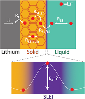
Figure 13. Schematic of interfacial phenomena for a protected lithium metal anode in a solid-liquid hybrid electrolyte cell.
Download figure:
Standard image High-resolution imageJanek et al provided new insight into the origin of RSE/LE by observing the formation of a solid-liquid electrolyte interphase (SLEI) at this solid electrolyte-liquid electrolyte interface [60]. That is, the liquid electrolyte can react with the solid electrolyte to form an interphase layer between the solid electrolyte and liquid electrolyte. This SLEI can have a profound influence on the performance of the battery, as the transport of lithium ions through the SLEI is not well understood. For example, Ea derived from RSE/LE were highest compared to Ea's derived from RSE,bulk, RSE,gb, and RLE in this work. Recent work has provided more insight into the complex nature of the SLEI and its impact on performance of hybrid solid-liquid electrolyte based batteries [61–64]. These studies observed that the SLEI originated from chemical and electrochemical reactions of the liquid electrolyte on the surface of the solid electrolyte and, depending on the solid electrolyte and liquid electrolyte, high RSE/LE values of 100–1000 Ω cm−1 were measured. Resistances of this magnitude cause large potential drops across the SE/LE interface, significantly decreasing the rate capability of hybrid solid-liquid electrolyte batteries. Similarly to the heavily investigated Solid Electrolyte Interphase (SEI) [65], these SLEIs predominately contain Li2CO3, with Li2O, LiF, and other decomposition products of the liquid electrolyte. Therefore, engineering the composition and morphology of the SEI should also be applicable to the engineering of the SLEI. A major challenge for the future will be designing and synthesizing an SLEI with high lithium-ion conductivity, low electronic conductivity, good wettability of both solid and liquid electrolytes, and which is also stable over a large temperature range and wide voltage window.
9.3. Advances in science and technology to meet challenges
Electrochemical and structural characterization of lithium ion battery materials has advanced significantly since the inception of commercial lithium ion batteries in the 1990's [66]. High precision potentiostats are readily available to probe the electrochemistry of these materials and can be coupled with a variety of characterization techniques. For example, microscopic and spectroscopic techniques with high spatial resolution are capable of resolving features at the atomic scale. Coupling these techniques will enable a reliable characterization of the SLEI. The application of a four-probe (4P) electrochemical impedance spectroscopy (EIS) measurement is vital for accurately determining the magnitude of RSE/LE, as shown by Abe et al, and Janek et al [58, 60]. The key advantage with 4P EIS is its ability to exclude resistance contributions from the counter electrodes during measurement, providing an accurate quantification of RSE/LE. Using electrode materials possessing minimal reactivity with the liquid electrolyte, such as LiFePO4 [63], will further improve quantification. Furthermore, two-probe and three-probe EIS, potentiostatic, and galvanostatic methods will continue to play an important role in evaluating the performance of hybrid solid-liquid electrolyte batteries. The composition of the SLEI can be determined by the many spectroscopic techniques used to characterize the SEI. For example, x-ray photoelectron spectroscopy (XPS) can be used to determine elemental composition and oxidation states of surface species, with an analysis depth on the order of tens of angstroms [67]. Coupling XPS with techniques such as Infrared Spectroscopy (IR) can help to identify specific molecules, which is especially useful for organic/polymeric species that may play a key role in the function of the SLEI. Other techniques, for example Nuclear Magnetic Resonance (NMR) Spectroscopy, Raman Spectroscopy, Gas Chromatography-Mass Spectrometry (GC-MS), etc can be used to identify liquid and gaseous products formed from the decomposition of electrolyte species, allowing for the complete SLEI reaction to be characterized. In situ analogues of these techniques are under current development, and will investigate these reactions in real time [66]. There is also opportunity to understand the morphology of the SLEI with microscopic methods. This includes in particular, but is not limited to: Transmission Electron Microscopy (TEM), Atomic Force Microscopy (AFM), and Scanning Electron Microscopy (SEM), which could all potentially be used to investigate important interfaces in battery technology [66]. Perhaps TEM is the most versatile of these, as it can be used to provide structural information with Selected Area Electron Diffraction (SAED), and compositional information with spectroscopic techniques such as Electron Energy Loss Spectroscopy (EELS) and Energy Dispersive Spectroscopy (EDS), with atomic resolution. Interestingly, AFM can not only image the surface with high precision, but can also be used to extract information on the mechanical properties of the SLEI, which has been recently demonstrated for the SEI [68]. In situ analogues of these techniques are also being developed [66], which can reveal nucleation and growth mechanisms during electrochemical reactions, applicable to growth/nucleation of the SLEI.
9.4. Concluding remarks
Hybrid battery concepts based on solid-liquid electrolytes are an exciting technology for enabling the fabrication of next generation high energy density batteries. A promising route in particular would be through the development of protected lithium metal anodes. With this new technology there are novel opportunities for exploring fundamental science, such as exploring the design and construction of the SLEI in order to minimize RSE/LE. A suite of analytical techniques will be required for complete electrochemical and structural characterization of the SLEI, providing the possibility for interdisciplinary work. In general, research regarding these solid-liquid interfaces will be valuable for improving the performance of energy storage technology, and providing insight into fundamental surface science.
Acknowledgments
The authors would like to acknowledge the financial support of the ISCF Faraday Challenge project SOLBAT [grant No. FIRG007] and the Henry Royce Institute (through UK Engineering and Physical Science Research Council grant EP/R010145/1) for capital equipment.
10. Polymer and composite solid electrolytes: role of polymers in solid-state batteries
Georgina L Gregory and Charlotte K Williams
Department of Chemistry, University of Oxford, Oxford OX1 3TA, United Kingdom
The Faraday Institution, Quad One, Harwell Campus, OX11 0RA, United Kingdom
10.1. Status
Polymers have many attractive properties for application in solid-state batteries. For example, their flexibility improves interfacial contact with electrode materials, as well as enhancing the stability of electrode volume changes upon cycling. They show lower flammability compared to liquid electrolytes, which ensures safer performance. Potential low cost and light-weight polymers, coupled with facile processability, are promising in terms of the realisation of scale-up and the fabrication of thin, flexible batteries with increased energy density. Polymers could play a focal role as bulk solid polymer electrolytes, connecting anode and cathode, or as crucial interface modifiers between an electrode and inorganic solid-state electrolyte, as well as functional (conductive or elastomeric) polymeric binders or coatings in composite materials. Dating back nearly 50 years to the initial discovery of lithium-ion conductivity of poly(ethylene oxide) (PEO), PEO and its derivatives still remain the dominant polymer class used in battery applications. This is attributed to the high Li-ion conductivity at temperatures > 60°C (10−3–10−4 S cm−1) owing to its low glass transition temperature, coupled with high oxygen density. Extensive research has focused on addressing the limiting room temperature ionic conductivity of PEO (10−7–10−8 S cm−1), a result of its high crystallinity as well as imparting desirable mechanical properties, overcoming the low lithium-ion transference number (0.2–0.3), and widening the electrochemical stability window, which is limited to 4 V. Various strategies have been used to improve upon the properties of PEO/salt electrolytes, including: copolymerisation, crosslinking, blending with other polymers, composites with inorganic materials, and modification to yield polymer single- ion conductors [69, 70]. Polymers other than polyethers have been investigated, including (but in no way exhaustive) polyalcohols, polyamines, polynitriles, polysiloxanes and polycarbonates [71, 72]. As yet, these materials show insufficient room temperature ionic conductivity and/or poor mechanical stability, highlighting the importance of continued research efforts within the field. Polycarbonates are of particular focus in this work for application in next-generation batteries, owing to their enhanced oxidative stability (4.5-5 V), which could enable the use of high-voltage cathode materials. Generally, higher lithium ion transference numbers (≥ 0.5) are also reported, and are important for improving cell performance.
10.2. Current and future challenges
A challenge in the design of polymers for battery applications is the simultaneous optimisation of both ionic conductivity and mechanical properties. Synthesis of well-defined block copolymers is an effective approach to decoupling ionic conductivity and mechanical properties. Microphase-separation of block copolymers into soft ion-solvating segments (e.g. PEO) and hard, mechanically rigid domains (e.g. polystyrene, PS) leads to enhanced mechanical stability whilst retaining the soft phase for ion transport. Typically, the reinforcement block for mechanical stability is non-conductive, but recently Cao et al investigated the introduction of conducting poly(propylene monothiocarbonate) (PPMTC) as an additional solvating block in block copolymers with PEO [73]. The double conductive phases in PPMTC-b-PEO/LiTFSI gave higher lithium-ion conductivities (2 × 10⁻⁴ S cm−1 at 25°C compared to PS-b-PEO/LiTFSI electrolytes with a single conductive phase (∼ 10−5–10−7 S cm−1 at 25°C), and storage moduli (G') up to 4 times greater than neat PEO/LiTFSI systems. A future direction may be to introduce a more rigid second conductive phase, as the G' was lower than PS-b-PEO/salt electrolytes due to the softer nature of PPMTC compared to PS. Another recent example of the utility of block copolymers in forming mechanically robust polymer electrolytes is the incorporation of random copolymers of trimethylene carbonate and ε-caprolactone as soft amorphous blocks in hard-soft diblock copolymers, employing poly(benzyl methacrylate) hard blocks. With 17 wt% LiTFSI, an ionic conductivity of 9.1 × 10⁻⁶ S cm−1at 30°C was reached, with a storage modulus (E') of 0.2 GPa, comparable to polystyrene. The solid polymer electrolytes showed oxidative stability up to ∼ 5 V, and an apparent transference number of 0.64 [74]. Single-ion conductors consisting of a weakly coordinating anion anchored to the polymer backbone is a common strategy to achieve cation transport numbers close to unity, and to prevent concentration gradients during cell operation. The current issue limiting their practical application is their low ionic conductivity, particularly compared to the corresponding polymer/salt systems. Tethering of the weakly coordinating anion trifluoromethanesulfonylimide (TFSI) to the polymer chain has been widely studied. Recently, single-ion poly(ethylene oxide carbonates) were investigated by Meccerreyes and coworkers, who were aiming to combine into one material three successful components of polymer electrolytes: ethylene oxide units, carbonate groups, and lithium-sulfonimide. The copolymers were synthesised by polycondensation between polyethylene glycol, dimethyl carbonate, and a functional diol bearing a pendant sulphonimide anionic group and lithium cation. The optimised copolymer had an ionic conductivity of 1.2 × 10⁻⁴ S cm−1 at 70°C, with 0.89 transference number [75]. This is comparable to the previously reported best electrochemical performance for these types of systems, which were based on PEO and methacrylic sulphonamide blocks [76]. In contrast, earlier work with similar UV-cross-linked poly(ethylene oxide carbonates) and LiTFSI salt (dual-ion conductors) gave higher ionic conductivities of 1.3 × 10⁻³ S cm−1 at 70°C. The optimised copolymer, comprised of PEO linked by polycarbonate segments with 10 wt% UV cross-linkable methacrylic pendant groups to form free-standing polymer films, also showed a high lithium transference number of 0.59 [77]. In contrast to polycondensation routes for the synthesis of polymer electrolytes, living ring-opening polymerisation strategies require less energy intensive reaction conditions and offer better control over polymer properties such as molecular weight, molecular weight distribution, and end-group fidelity. Particularly attractive, from a raw materials availability consideration for next generation batteries, are those prepared by the controlled ring-opening copolymerisation of CO2 and epoxides. For example, Meng and coworkers prepared functional CO2-based polymers by terpolymerisation of propylene oxide, allyl glycidyl ether and CO2 catalysed by zinc glutarate. Efficient, facile post-functionalisation with a lithium carboxylate yielded stand-alone polymer films exhibiting electrochemical stability up to 4.3 V vs. Li+/Li, and a high lithium transference number of 0.86 (though with moderate ionic conductivity) [78]. Poly(propylene carbonate) synthesised by the alternating copolymerisation of CO2 and commercially relevant propylene oxide has attracted a lot of interest. Deng et al developed composite electrolytes with poly(propylene carbonate) and LLZTO, showing oxidative stability up to 4.6 V, ambient ionic conductivity of 5.2 × 10⁻⁴ S cm−1, a high ionic transference number (0.75), and reasonable mechanical strength (6.8 MPa) [79].
10.3. Advances in science and technology to meet challenges
Advances in our understanding of the behaviour of polymers within the battery environment is critical to designing polymers for solid-state batteries that meet the combined requirements of high ionic conductivity, high cation transference number, excellent mechanical properties, and electrochemical stability. This includes a deeper consideration of the structure-property relationships of polymer-based materials, in particular polymer degradation mechanisms. With this aim in view, Oyaizu and co-workers recently compiled a large database of lithium-ion conducting polymers (104 entries) containing information about chemical structure and conductivity. Machine learning models suggested unexpectedly that more glassy polymers, rather than the more traditionally focused upon rubbery polymer electrolytes, could offer improvements in ionic conductivity, and decoupled from polymer chain segmental motion [80]. DFT studies were carried out to investigate the interface between various solid polymer electrolytes and lithium. Calculated absorption energies indicated the stronger adhesion of ester, carbonate and nitrile polymer functional groups to lithium metal, as compared to PEO and poly(vinyl alcohol). However, a higher reactivity was predicted for polycarbonates and polyesters to form CO and alkoxide products [81]. Experimentally, end-capping of poly(ethylene carbonate) based electrolytes with acetate groups led to improved oxidative tolerance (5.4 V vs. Li+/Li) with 120 mol% LiTFSI compared to the non-end-capped (hydroxyl-terminated) polymer (∼ 5.0 V). This implies that alkoxide backbiting could accelerate polymer degradation under oxidative conditions, and can be inhibited by a simple modification of the polymer chain end-group [82].
10.4. Concluding remarks
Polymers present several opportunities for solid-state batteries. Extensive research has focused on their role as solid polymer electrolytes, and improving ionic conductivity alongside mechanical robustness. Several approaches have demonstrated great strides towards this goal; for example, the design of phase separated block copolymer electrolytes and anionic polymer backbones. Nevertheless, the potential role of polymers as binders in modifying the interface between inorganic solid-state electrolytes and electrode materials is often overlooked. For example, the development of new polymer binders with elasticity or self-healing properties could deliver improvements to cycling stability. Polymer design for applications in solid-state batteries should draw upon controlled polymer synthesis strategies that provide well-defined polymers to facilitate a systematic study of structure-property relationships. The ring-opening copolymerisation of CO2 and epoxides is one example of a controlled polymerisation methodology, and offers potential advantages in terms of raw material availability and the formation of polycarbonates with good electrochemical stability.
Acknowledgments
This work was supported by The Faraday Institution [challenge SOLBAT, grant No. FIRG007].
11. Garnet solid electrolytes
Hany El-Shinawi1,3, Innes McClelland1,3, Edmund J Cussen1,2,3 and Serena A Corr1,2,3
1 Department of Chemical and Biological Engineering, University of Sheffield, Sheffield S1 3JD, United Kingdom
2 Department of Materials Science and Engineering, The University of Sheffield, Sheffield, S1 3JD, United Kingdom
3 The Faraday Institution, Quad One, Harwell Campus, OX11 0RA, United Kingdom
11.1. Status
The garnet stoichiometry of A3B2C3O12 presents an exciting playground for the crystal chemist investigating dopant or vacancy effects on conductivity properties in these promising candidate solid ceramic electrolytes [83–86]. The capacity for incorporating a wide range of cations into various sites in the garnet structure, as shown in figures 14 (a) and (b), has afforded a wealth of compositional variability, recently captured in a review by Thangadurai and co-workers [87]. The promise of garnets lies in their high ionic conductivities (∼ 10−3–10−4 S cm−1 at room temperature) as well as their apparent lack of reactivity with lithium metal, although recent reports challenge us to reconsider the basis for this stability. Opportunities for further development remain, specifically in the scaled-up synthesis of high-performance materials, that potentially afford compositional and microstructural control, in realising the chemical stability of these materials under ambient conditions, and in understanding and manipulating local interfacial structure to improve transport properties and avoid degradation. Visualising and fine-tuning the ion mobility in lithium-stuffed garnet frameworks LixLn3M2O12 (where Ln is a lanthanide and x> 3) demands an detailed assessment of cation distribution. It is well-established that the zirconium-based Li7La3Zr2O12 (LLZO) garnet can adopt two polymorphs: the high ionic-conducting cubic phase, stabilised at room temperature through aliovalent substitution (e.g. with Al3 + or Ga3 + ), and the tetragonal phase, whose ionic conductivity is lower owing to the absence of disorder which facilitates lithium hopping. Lithium occupational disorder may also be induced by substitution of Ta5 + or Nb5 + for Zr4 + in LLZO, giving rise to high bulk conductivities on the order of ∼ 1 mS cm−1 (table 1).

Figure 14. Crystal structure representations of (a), (b) Al-doped LLZO garnet and (c–e) Li6PS5X (X = Cl, Br) solid state electrolytes. The cubic phase garnet in (a) is represented by Zr ions (purple, with polyhedra shown), La ions in blue, lithium ions in green, and oxygen in orange. (b) shows the distribution of lithium ions in tetrahedral (polyhedra shown) and distorted octahedral positions in the cubic garnet framework, viewed along the [110] direction. The argyrodite phase Li6PS5Br is shown in (c), where white spheres represent lithium ions, yellow represent sulphur, purple spheres are phosphorus ions, maroon spheres represent 4a sites where Br/S anion site disorder is observed, and blue spheres represent 4d disordered Br/S sites. The lithium site disorder for the Li6PS5Br phase is shown in (e), in contrast to the chloride analogue (d) where lithium is found only on the 48 h site.
Download figure:
Standard image High-resolution imageTable 1. Physicochemical properties of garnet and argyrodite candidate solid electrolytes.
| Garnet Family | Argyrodite Family | |
|---|---|---|
| Ionic conductivity (mS cm−1) | ≈ 10−3–1 | ≈ 10−7–10 |
| Activation energy (eV) | ≈ 0.19-0.58 eV | ≈ 0.16-0.68 eV |
| Electronic conductivity (S cm−1) | LLZO, ≈ 10−8–10−7 | Li6PS5Cl, ≈ 10−9–10−8 |
| Practical upper voltage windowa | LLZO, ≈ 3.6 V vs. Li+/Li | Li6PS5Cl, ≈ 2.2 V vs. Li+/Li |
| Shear modulus | LLZO, ≈ 60 GPa | Li6PS5Cl, ≈ 8 GPa |
| Stability in ambient conditions | Store under dry conditions to avoid Li+/H+ exchange which can promote Li2CO3 formaion. | Require dry atmosphere due to propensity for hydrolysis reactions. |
aPractical upper voltage windows are based on redox activity of the solid electrolyte during (de)lithiation [88].
Thermodynamic interface stability is highly dependent on the nature of the dopant introduced [89, 90]. The stability of doped variants against lithium metal is a property which continues to necessitate careful assessment, as the dopants themselves may be susceptible to oxidation state changes, which has implications for any interphase formed. With the advent of machine learning techniques and high throughput screening, it is possible to investigate this cation dopant effect on interfacial stability and, on the basis of this, predict new potential structures which warrant further investigation [91].
11.2. Current and future challenges
To assess interphase formation and to determine critical parameters such as ionic conductivities, highly dense pellets of the parent powder are needed for which the primary particle size is a crucial determining factor. Typically, high sintering temperatures and prolonged reaction times are applied to densify garnet powders, yet these run the risk of lithium loss or the formation of impurity phases, both of which result in lower ionic conductivities. Spark plasma sintering (SPS) presents an approach which allows densification at lower temperatures and shorter times, but specialist equipment and expertise are needed. There are considerable opportunities, therefore, for developing synthetic strategies which permit microstructural control, as well as surface chemistry manipulation to avoid surface contaminants. Chemical stability and handling of garnet electrolytes in ambient conditions is another pertinent challenge. Reaction with moisture and CO2 can lead to a surface layer of Li2CO3 driven by Li+/H+ exchange, which has a deleterious effect on interfacial contact and the resulting ionic conductivity, since Li2CO3 will preferentially grow along grain boundaries [92]. Understanding and mitigating this surface effect demands further study. For example, faster cooling rates after calcination could prevent Li2CO3 formation, and alternative heat treatments such as microwave methods may enable this [93]. The primary grain size may also play a role, where smaller grains may be less prone to Li2CO3 formation, although the nature of this effect remains unclear. Hand-in-hand with crystal structure optimisation must come particle processing and microstructural tuning, whereby greater control over the interfacial resistances may be possible through architectural manipulation of particle surfaces and subsequent control over interphases. Alternatively, additives could be sought which promote stability, as exemplified by the recent work of Goodenough and co-workers [94], who have demonstrated stabilisation at the interface in Ta-doped LLZO by the addition of 2 wt% LiF. While the majority focus has been on elevating the ionic conductivity of garnet, recent work [95] has undertaken a closer inspection of the role played by electronic conductivity in the evolution of lithium dendrites (table 1). This observation, using operando neutron depth profiling, of lithium dendrite formation in LLZO-based electrolytes highlights the need for established boundary conditions for electronic conductivities in candidate solid electrolytes.
11.3. Advances in science and technology to meet challenges
Synthetic advances affording microstructural and primary particle size control could provide rational insights into how densification and interfacial properties could be governed. For example, reducing the Al-doped LLZO particle size has been shown to decrease the densification temperature for attaining free-standing thin films with fewer grain boundaries [96]. Our own efforts [97, 98] at developing sol-gel based chemistries have resulted in shorter calcination times to access Al-doped LLZO, where densification is aided by the in situ formation of LiAlO2. Such routes have also seen dense sol-gel derived electrolytes, which display total conductivities comparable to SPS-treated materials. The application of advanced microscopy methods has enabled a finer inquiry into LLZO-interface formation. In an elegant examination by aberration-corrected scanning transmission microscopy, Chi and co-workers [99] have shown that the immediate surface (up to five unit cells) of Al-doped LLZO is reduced on contact with lithium metal to form the lithium-rich tetragonal LLZO phase. While the tetragonal phase is the low ionic-conducting polymorph, its presence here is favourable, as it limits further interfacial reactivity. The reported ionic conductivities of ceramic solid electrolytes can vary considerably. The adoption of a synthetic approach may give rise to compositional or microstructural variability, inducing changes in lithium concentration or grain boundary surface area which would inevitably be reflected in the measured ionic conductivity. The measurement technique itself may introduce user-based differences, since comprehensive universally-agreed procedures do not exist, for example for standard impedance analysis. Interestingly, this idea of interlaboratory reproducibility has been investigated by a team led by Zeier,who demonstrate the considerable deviation in total ionic conductivities and activation energies for identical samples measured across multiple laboratories [100]. Such a call to the community for rigorous measurement methodologies and established testing criteria is well-timed. Advances in applying local dynamic tools such as muon spectroscopy to interrogate self-diffusion properties, as well as operando measurements, will overcome the sensitivities of grain boundaries or surface effects [101]. Developing large-scale processing techniques remains a crucial bottleneck to be overcome in the realisation of solid-state batteries. The inherent challenge here is to scale-up without compromising ionic conductivity. Recently, Rupp and co-workers [102] have developed a multilayer-based technique using PLD, which employs Li3N as a lithium reservoir capable of reducing the stabilisation temperature of Al-doped LLZO by several hundred degrees. What is particularly exciting about this development is its general applicability, which allows precise control over the lithium concentration, as well as lower processing temperatures.
11.4. Concluding remarks
Extensive efforts have been made in enhancing ionic conductivities in garnet materials through compositional control, and research continues in optimising particle morphology. Considerable gains can be made in engineering tailored garnet surfaces which stabilise the electrode-electrolyte interface without detriment to its ionic conductivity. Whether the greatest benefit comes from designer interfaces, or coatings introduced post-synthesis, or via a coating formed in situ during cycling remains to be seen. The recent interest in probing garnet electronic conductivity opens this up as a potential diagnostic tool for predicting lithium dendrite formation. Finally, engineering the scaled-up production of ceramic electrolytes for solid-state batteries will require some novel thinking, such as smart multilayers, targeted morphologies for optimal packing, or symbiotic electrolyte composites.
Acknowledgments
The authors gratefully acknowledge the support of the ISCF Faraday Challenge project SOLBAT [grant No. FIRG007], the EPSRC [EP/N001982/2], the University of Sheffield for support and the ISIS Neutron and Muon Facility through the award of a Facility Development Studentship for IMC.
12. Sulphide solid electrolytes
Christopher I. Thomas2,3, Serena A Corr1,2,3 and Edmund J Cussen1,2,3
1 Department of Chemical and Biological Engineering, University of Sheffield, Sheffield S1 3JD, United Kingdom
2 Department of Materials Science and Engineering, The University of Sheffield, Sheffield, S1 3JD, United Kingdom
3 The Faraday Institution, Quad One, Harwell Campus, OX11 0RA, United Kingdom
12.1. Status
The search for new solid electrolytes is being driven by the desirability of metallic lithium anodes, and the associated increase in volumetric energy storage, obviating the need for graphitic anodes. Sulphides have some general advantages over oxide materials: the more polarisable sulphide anion should provide a lower electrostatic barrier to ion migration, weaker bonding leads to materials that densify at lower temperatures, and softer materials may be more forgiving of the changes in electrode volume during battery cycling. Key parameters are summarised in table 2. Fast Li+ conduction has been observed in a number of glassy sulphides based on tetrahedral PS and di-tetrahedral P2S
 units that also show variable thermal stability [103]. The glass-forming nature of these systems is a challenge, and sulphide electrolytes have generated a surge in interest following reports of fast Li+ conduction in related crystalline phases such as Li10GeP2S12 and Li6PS5Cl [104, 105]. The dependence of charge transport on chemical composition can be highly non-linear, and extensive characterisation is necessary to avoid situations such as have arisen in Li7La3Zr2O12 (LLZO) and 'beta-alumina', where the initial chemical composition omitted the key enabling elements (Al and Na, respectively) for the delivery of electrolyte properties. In the case of potentially glass-forming systems such as thiophosphates, it is crucial that a crystalline structure derived from Bragg scattering is a meaningful approximation of the whole sample, and advances in pair distribution analysis have provided great insight here [106]. A common component across fast ion conducting systems is a disordered crystal structure; in argyrodites, Li distribution and anion ordering can be manipulated by compositional adjustments of the halide, or by the replacement of P5 + with Si4 + , Ge4 + , or Sb5 + to tune electrolyte performance [106, 107].
Table 2. Physicochemical properties of garnet and argyrodite candidate solid electrolytes.
| Garnet Family | Argyrodite Family | |
|---|---|---|
| Ionic conductivity (mS cm−1) | ≈ 10−3–1 | ≈ 10−7–10 |
| Activation energy (eV) | ≈ 0.19-0.58 eV | 0.16-0.68 eV |
| Electronic conductivity (S cm−1) | LLZO, ≈ 10−8–10−7 | Li6PS5Cl, ≈ 10−9–10−8 |
| Practical upper voltage windowa | LLZO, ≈ 3.6 V vs. Li/Li+ | Li6PS5Cl, ≈ 2.2 V vs. Li/Li+ |
| Shear modulus | LLZO, ≈ 60 GPa | Li6PS5Cl,≈ 8 GPa |
| Stability in ambient conditions | Store under dry conditions to avoid Li+/H+ exchange which can promote Li2CO3 formaion. | Require dry atmosphere due to propensity for hydrolysis reactions. |
aPractical upper voltage windows are based on redox activity of the solid electrolyte during (de)lithiation [88].
12.2. Current and future challenges
The major challenges facing sulphide electrolyte materials arise in chemistry, preparation, stability, and interface management. Understanding chemical stability and solid electrolyte behaviour requires a detailed appreciation of the chemistry of the host lattice and its interactions with the mobile Li+. The argyrodite structure contains a face-centred cubic (fcc) anion lattice with PS4 − occupying the octahedral interstices. In Li6PS5I, the relatively large size difference between S2 − (1.84Å) and I− (2.20Å) drives complete anion-ordering, with iodide on the fcc sites, and sulphide filling half of the tetrahedral interstices. Decreasing the halide size leads to partial anion mixing for bromide and sulphide. For Li6PS5Cl, the smaller radius of Cl− (1.81Å) leads to an enrichment of the fcc sites with sulphur, with the chloride being the majority occupant of the tetrahedral interstitial sites. This change in anion distribution has a profound effect on the lithium arrangement, with Cl− having a 50% occupied 48 h site, and Br− and I− having a more disordered arrangement of Li+ over two sites in the structure. Compared to Li6PS5Cl, the increasing lithium disorder and larger lattice parameter associated with bromide materials results in a slight decrease in the activation barrier for Li+ mobility [106]. Conductivity falls away rapidly with the introduction of larger iodide, which drives the anions into a fully-ordered arrangement. The lithium electrolyte performance of argyrodites is also manipulated via the replacement of P5 + with isovalent Sb5 + or tetravalent Si4 + or Ge4 + , affording a solid solution such as Li6 + xSixSb1 − xS5I [107]. The lower conductivity associated with the complete ordering of the I−/S2 − ions is more than offset by the increased disorder in the lithium, with the additional Li+ cations being incorporated into the 24g site. This increases the level of conductivity to > 0.01 S cm−1, but there is some indication that secondary impurity phases may segregate to grain boundaries, limiting the overall performance of the material. Impurities, grain boundaries and segregation are some of the considerable challenges of synthetic scale-up and electrolyte manufacture for argyrodites. These materials are often made at gram-scale, using extensive mechanical milling of chemical reagents for up to 10 hours. New simplified chemical pathways for obtaining these materials are still reliant on inert protective atmospheres and reactions performed inside sealed quartz tubes [108]. Long-term cycling stability with metallic lithium remains the great prize, but our understanding of the failure modes of these solid electrolytes in a lithium battery is incomplete. A recent comparison of sulphide with other electrolytes concluded that the electrical conductivity of the electrolyte material is a primary factor in determining whether metallic lithium is formed under cycling conditions [95]. This interesting proposition requires further testing.
12.3. Advances in science and technology to meet challenges
The demand for a solid electrolyte technology is driving scientific understanding of the key processes of lithium transport within and between particles. Recent examples have shown creative application of multiple properties measurements to determine where the lithium electrolyte performance is being limited. The incorporation of softer anions, e.g. by partial replacement of Cl− with the larger Br−, is envisaged to reduce the barrier to Li+ migration between sites within the crystal. It has been less anticipated that softening the lattice reduces the phonon frequency and as a consequence the vibrational timescale is extended. This means that although the softer lattice increases the probability of a successful Li+ ion jump, the jump is attempted at a lower frequency, and ionic conductivity may be reduced [106]. Hence, softening the lattice is associated with effects that both potentially enhance and diminish the rapidity of ionic migration through the crystal structure. As the conductivity of sulphides has increased, it has focussed attention on the requirements for operation in a solid-state battery, particularly the ability of Li+ cations to move through the macroscopic electrolyte assembly and into the electrode materials. Although lithium mobility in the crystal structure can match that of liquid electrolytes, there remain considerable challenges in terms of managing grain boundaries and interfaces. Local probes, such as NMR, can resolve the intra- and inter-cage Li+ transitions, with the latter being the rate-determining step for Li+ transport within a single crystal of Li6PS5Cl. Most importantly, measurements on a Li6PS5Cl/Li2S electrolyte/electrode composite show that the key determinant of high rate battery performance is the exchange of Li+ cations between the argyrodite and the Li2S electrode [109]. The power applications of a solid-state battery based on this chemical system may be limited by electrolyte/electrode interface and composite (nano)structure. However, the full extent of ion conductivity in argyrodite cannot be exploited without further engineering of particle/particle electrolyte/electrode interfaces. A great advantage of solid electrolytes is their wide thermal stability window. Operation both at low and high temperatures indicates that exceptional performance, including high charge rates (up to 18°C), can be realised [104, 107]. The dependence of battery degradation on charging rate and thermal history is not completely understood for conventional Li-ion batteries, and the potential for using thermal control to facilitate fast, safe charging of solid electrolyte systems may be even greater due to the extended thermal stability range of these electrolytes [110].
12.4. Concluding remarks
Key challenges remain in the development of sulphide electrolytes suitable for solid-state batteries, relating to stability, scale-up, and electrolyte/electrode architecture. Recent advances in the experimental interrogation of interfaces, and proposed models of electrolyte stability with metallic lithium, suggest avenues for tailoring known phases towards materials more suited to meet these challenges.
Acknowledgments
The authors gratefully acknowledge the support of the ISCF Faraday Challenge project SOLBAT [grant No. FIRG007], the EPSRC [EP/N001982/2], and the University of Sheffield for support.
13. Crystal structure prediction and experimental realisation of inorganic solid electrolytes
Elvis Shoko and Matthew S Dyer
Department of Chemistry, University of Liverpool, Liverpool L69 7ZD, United Kingdom
The Faraday Institution, Quad One, Harwell Campus, OX11 0RA, United Kingdom
13.1. Status
Starting from the periodic table of the elements and arriving at an entirely new commercial material satisfying specific performance requirements is one of the greatest challenges of modern materials science. Undoubtedly, the path between starting point and destination can be extremely complex, often demanding the development of new cutting edge tools to address various challenges along the way. With its objective of finding novel inorganic solid electrolytes to enable step advances in solid-state Li-ion batteries, the materials discovery aspect of the SOLBAT project lies firmly in this realm. The ideal inorganic solid electrolyte should exhibit high room-temperature Li ionic conductivity (> 1 mS cm−1), zero electronic conductivity, a wide electrochemical window for compatibility with both high-voltage cathodes and Li metal anodes, and mechanical/permittivity characteristics that suppress dendrite formation [111]. These (aspirational) requirements shape the main workflow for the materials discovery part of the SOLBAT project, as shown in figure 15. The main tools employed lie in the disciplines of crystal structure prediction, synthesis, and characterisation. We have excluded the parallel effort of the search for solid electrolytes from databases of known materials, either directly or by chemical analogy.

Figure 15. Materials discovery workflow for the SOLBAT project. The main elements are material system (phase field) selection, composition space sampling within a phase field, crystal structure prediction for the different compositions based on the thermodynamic convex hull (stability test), synthesis trials for promising compositions, and characterisation of any compounds successfully synthesised. Information feedback is shown by the thin arrows: yellow—compositions failing the stability test guide further composition space sampling, dotted red—compositions failing the synthesis test lead to refinement of both the stability test and composition space sampling, red—successful compositions guide further composition space sampling, crystal structure prediction (they are added to the convex hull), and the stability criterion.
Download figure:
Standard image High-resolution imageCrystal structure prediction (CSP) has developed to the point where it is now virtually an applied technology [112]. There are several approaches for implementing CSP, including evolutionary (e.g. XTALOPT [113]), particle swarm (e.g. AIRSS [114]), and basin hopping (e.g. ChemDASH [115], an in-house code in our group) algorithms. ChemDASH has been the CSP workhorse for the SOLBAT project, employed within the philosophy of the probe structure approach [116]. This approach only aims to find a probe structure (i.e. a crystal structure with coordination environments that are representative of the ground state) rather than the ground state itself, thus reducing the cost of the CSP. The probe structure approach is intimately coupled with experimental synthesis. The search for the ground state is completed through synthesis trials at or near the chemical compositions where the most promising probe structures (based on energy above the convex hull) are found. If the experimental ground state is found, both computational and experimental tools are employed in tandem for the characterisation of the new compound. Computational tools for assessing ionic conductivity include bond valence sum mapping for preliminary screening, the nudged-elastic band for energy barriers along predefined plausable migration pathways, and molecular dynamics (ab initio, empirical or machine learning potentials) for a more detailed mapping of conduction pathways, energetics, and transport coefficients at finite temperatures. On the other hand, electrochemical impedance and NMR spectroscopy techniques are commonly used to characterise ionic conductivity experimentally. Electronic conductivity is undesirable, and standard electronic structure calculations are performed to determine the electronic band gap. Other key factors include electrochemical stability and mechanical properties; both computational and experimental tools exist for their evaluation.
13.2. Current and future challenges
We mainly consider challenges around the CSP step because of its high cost. At the front end of the solid electrolyte discovery process is a vast two-tier chemical space representing all possible material systems (crystallographic phase fields) and all of the different chemical compositions within a given phase field. Each of these exhibits a combinatorial explosion that precludes any possibility of exhaustive exploration, even with the most advanced high-throughput methods. Consequently, some scheme for sampling the vast chemical space is required in order to make progress, and the question of how this sampling should be performed is increasingly looming large at the front end of CSP. Mathematically, phase field selection is a problem of sampling from the vast combinatorial manifold of all possible combinations of the chemical elements of the periodic table. Admittedly, this manifold is reduced by restricting the search to only chemically meaningful combinations, but it remains extremely large. At this stage, the experienced chemist, based on domain knowledge, typically selects elements commonly found in known electrolytes and combines them in familiar ways. The notion of chemical similarity can be employed in a limited way to derive compounds analogous to known electrolytes. The validity of this approach as a reliable guide to materials discovery is increasingly coming under scrutiny. It unduly restricts the search space, and could even perform worse than random selection [117], making it ill-suited to the discovery of novel materials. Composition space sampling, i.e. choosing a tractable set of compositions to explore the phase field energy landscape, is the second tier of the CSP front end. Not much is known yet about the structures of multinary phase field energy landscapes, especially at higher dimensions than ternary. The CSP step constrains the number of atoms, N, in a chemical composition (N ∼ 100 atoms). However, even when N is constrained to be compatible with the CSP step, the space remains too large to search exhaustively. For example, in our study of a quinary system, we found ∼105 compositions in the computable space (N ≤120), but only ∼102 could be calculated. The key question is how to obtain these ∼102 compositions so as to maximise the yield of synthesisable compounds from the phase field. Fundamentally, the search for novel solid electrolytes is a multiobjective problem, requiring a search on the Pareto front of all key properties. This is a major challenge with current tools, and our approach is to prioritise only ionic conductivity at the front end of the search process. The hope is that if a good Li-ion conductor is discovered, it may be possible to engineer the other key properties into the material. Even with ionic conductivity as the only prioritised property, its computational evaluation can be significantly expensive if reliable finite temperature characterisation is required, as this entails the use of ab initio molecular dynamics (AIMD). One way to reduce the cost of AIMD is to perform simulations at high temperatures (say, > 500 K) but this is often still not sufficient to permit processing of a large number of systems. Instead, one resorts to classical molecular dynamics; however, the force fields required may be difficult to construct and, in general, are not transferable.
13.3. Advances in science and technology to meet challenges
While the challenges are clearly enormous, there are growing efforts to tackle them from a range of angles. One of the most promising avenues is machine learning (ML) [118], driven by growing materials science databases [119] and the emergence of automated ML workflows for materials discovery (e.g.,ChemML [120]) along with libraries of descriptors (e.g. DScribe [121]), as well as the shift towards explainability of ML surrogate models. Some early promising results from ML in solid electrolyte research have been reported, ranging from standard regression models [122], through black-box optimisation algorithms [123], to the prediction of conductors based on chemical composition alone [124]. Efficient methods for sampling the front end of the CSP step are an indispensable part of the solid electrolytes road map. As ML approaches based on chemical composition alone continue to be developed, they could offer a promising route towards addressing this challenge. These approaches will need to be coupled with active learning ML tools to achieve an optimal trade-off between exploration and exploitation of these large chemical spaces. However, ML approaches in materials discovery still need to overcome the limitations of training data insufficiency (both in volume and diversity) and predictive uncertainty quantification. Various strategies are currently being investigated to alleviate the problem of small training datasets, including data augmentation (e.g. using generative models), and transfer learning, in which models trained on physically related properties where data is sufficient are repurposed for the target property where data is insufficient. Nonetheless, it is apparent that the prospect of integrated platforms where the multiobjective problem is substantially automated, centred around active learning ML protocols, is becoming increasingly likely. This is expected to accelerate breakthroughs in the search for novel solid electrolytes for Li-ion batteries. Lastly, as the balance gradually tips away from a primary dependence on domain expertise in materials discovery towards more objective and high-throughput ML models, the transition needs to be matched with new research funding models. Such funding models should deliberately create a space for novel research in the scenario of calculated risk offered by ML exploration.
13.4. Concluding remarks
In conclusion, the immediate horizon should see a greater integration of CSP with more sophisticated ML tools, unlocking new and more efficient workflows for the accelerated discovery of inorganic solid electrolytes. However, CSP is expected to remain as a bottleneck to those workflows due to its high cost. Since CSP is merely a surrogate for predicting material synthesisability, workflows that partially or even completely eliminate it are expected to emerge in the long-term.
Acknowledgments
We are grateful to the ISCF Faraday Challenge project SOLBAT [grant number FIRG007] and to the UK Materials and Molecular Modelling Hub for computational resources, which is partially funded by EPSRC (EP/P020194/1).
14. Manufacturing of solid-state batteries
Christopher Doerrer, Junfu Bu and Patrick S Grant
Department of Materials, University of Oxford, Oxford OX1 3PH, United Kingdom
The Faraday Institution, Quad One, Harwell Campus, OX11 0RA, United Kingdom
14.1. Status
The manufacture of conventional Li-ion batteries involves separate lines of manufacture for anodes and cathodes coated onto foil current collectors, which are then integrated with a polymer separator, followed by various packaging operations, including injection of the liquid electrolyte. The process is characterised by high productivity, but a large number of process steps. So far, the manufacturing approach for solid-state batteries (SSBs) has followed a similar approach of discrete manufacturing processes for anode, cathode and electrolyte; however, the electrolyte tends to be formed first, and the positive electrode (a powder-based composite of the active cathode material, carbon and the solid electrolyte) and the Li-metal negative electrode (anode) are then added in separate operations. The electrolyte, usually either an oxide (e.g. Li7La3Zr2O12 (LLZO)) or a sulphide (e.g. Li6PS5Cl), is generally required to be largely pore-free to maximise ionic conductivity. Sulphides offer a manufacturing advantage because they can be pressed to a high density at room temperature. In contrast, oxides tend to require relatively high process temperatures (up to 1000 °C or even higher) and pressures (up to 500 MPa) for up to several hours' sintering for useful density and ionic conductivity [125]. When the oxide electrolyte is mixed with carbon and an active material, and consolidated to form a positive electrode, these high pressing temperatures tend to lead to excessive reactions and burn out of the carbon. Both oxides and sulphides exhibit sensitivity to water vapour, with LLZO forming unhelpful but essentially benign Li2CO3 whereas sulphides generate highly problematic toxic H2S gas. Thus, for sulphide-based SSBs in particular, manufacturing must be performed in a dry room or under inert atmosphere.
14.2. Current and future challenges
14.2.1. Electrolytes
The most widely explored SSB electrolytes are fabricated from hot pressed powders. While hot pressing has been popular for research purposes [126], it constrains the options for scale-up beyond the laboratory. Dense oxide-based electrolytes produced by uniaxial hot pressing are usually disc-shaped pellets, difficult to produce in diameters of 5 cm or more without cracking. As-manufactured thickness is also typically and unhelpfully approximately 1 mm, which may be reduced by polishing to 100 µm or less, but avoidance of cracking is extremely difficult. Approaches to reducing these problems include the use of sintering aids to reduce hot press time and pressure, and tape casting. Another approach is composite electrolytes where, for example, a part-sintered porous LLZO layer is 'back-filled' with a polymeric Li-ion conductor, such as those based on PEO [127]. These composite electrolytes may be more mechanically compliant and tougher, and thus realisable over larger areas at sub-millimetre thicknesses, without excessive cracking.
14.2.2. Anode
The relatively low reactivity of solid electrolytes allows a high specific capacity Li-metal anode to be used, which is essential to compensate for the higher intrinsic density of solid compared with liquid electrolytes. A thin Li layer anode is usually applied by thermal evaporation and deposition under vacuum, or by the pressing of a Li foil, onto the pre-formed electrolyte. Typically, an overall Li thickness of 10–30 µm is required to enable competitive cell-level volumetric and gravimetric energy densities. Thermal deposition requires the electrolyte surface to have good wetting properties, which may not always be applicable, and deposition costs become significant for practical anode thicknesses and areas. In many cases, interlayers are added to the anode/electrolyte interface (by evaporation, sputtering, pulsed laser deposition, atomic layer deposition, etc) in an attempt to improve wetting, stability and mechanical compatibility, and to reduce impedance [128]. While foil anodes are more straightforward, poor wetting (often due to Li surface contamination/reactivity) and resulting high resistance is typical. The price of Li foil also tends to increase with decreasing thickness and, so far, few manufacturers are able to produce sheets below 50 µm. An alternative approach involves so-called anode-free SSBs, where the Li-metal anode is formed in situ by electrochemical plating during the first battery charge [129], which in theory at least is highly scalable and simple from a manufacturing standpoint.
14.2.3. Cathode
Key challenges for the manufacture of the composite cathode are to ensure simultaneous interconnectivity of the solid electrolyte for Li-ion movement throughout the cathode, interconnectivity of carbon for ubiquitous electron percolation, intimate contact of all active particles with the electrolyte (which is typically more difficult for 'hard' oxides than 'soft' sulphides), including during cycling when the active material typically swells/shrinks, and a minimised fraction of electrolyte and carbon overall to boost specific capacity. The target composite cathode thickness depends on the Li-metal anode thickness and the fraction of cathode active material, but typically lies in the range 30–150 µm [1]. So far, most composite cathodes are manufactured by variants of slurry casting, with or without subsequent hot pressing.
14.3. Advances in science and technology to meet challenges
Given the restrictive nature of hot pressing methods for ceramic electrolyte or composite cathode layers (relatively small area, high thickness and low toughness/compliance), the use of polymer materials is a promising trend for enabling the fabrication of SSBs. Polymer engineering is mature, and provides opportunities to simultaneously engineer mechanical and functional properties. For example, polymer ionic conductivities (10−8–10−4 S cm−1) may not yet match sulphides (10−3–10−2 S cm−1) but used as part of composite electrolytes (above), coatings on individual cathode particles (preferably using simple, scalable solvent based processing) or at the interfaces between the electrolyte and the composite cathode, they can confer improved cell-level mechanical and electrochemical stability [129]. Composites can also facilitate the use of non-hot press routes to SSBs. For example, figure 16 is a scanning electron microscopy (SEM) image of the cross-section of a composite cathode based on active LiCoO2 (LCO) mixed with Ta-doped LLZO (LLZTO), onto which an LLZTO electrolyte layer was then deposited. Both cathode and electrolyte layers contained 5% inorganic binder and 5% Al2O3 as a sintering aid. Each layer comprised three relatively thin sub-layers of ∼ 5 µm, rapidly pressure-less sintered for the temperatures and times indicated, before the next layer was added. Marked densification was realised without application of pressure, while carbon was retained successfully. A cell was then formed simply by adding a Li foil as an upper layer. A similar approach has been used to produce high performance SSBs using a composite solid electrolyte based on PEO(LITFSI) mixed with Li1.5Al0.5Ge1.5(PO4)3 [130], as well as all-polymer symmetric solid-state cells in which a polymeric anode, electrolyte and cathode were sequentially sprayed to form an all-polymer cell in a single operation [131]. For these systems, aqueous and/or alcohol based suspensions, spraying under ambient conditions and avoiding any hot-pressing, provides for a potentially scalable approach for cathodes and electrolytes, guaranteeing fast processing while maintaining acceptably low levels of contamination. Sulphides and oxides can be processed by classical dispersion approaches under an inert environment; however, some sulphides e.g. Li6PS5Cl can also be used in dissolution/reprecipitation methods, in which the sulphide coats directly onto cathode particles on reprecipitation [132]. Even though in situ reprecipitation may reduce ionic conductivity, electrolyte/active material contact can be improved throughout the cathode, giving an overall improvement in cycling performance. Figure 17 shows the Nyquist plot obtained for a 60 µm thick binder-free sulphide film comprising 30 individual sulphide layers that were sprayed and re-precipitated in situ from an isopropanol/Li6PS5Cl mixture. This shows that dissolution/reprecipitation approaches may be attractive for manufacturing thin (15–40 µm) ionically conductive layers between SSB electrodes, as well as for infiltrating porous cathodes.

Figure 16. Three spray layers of a composite cathode containing LiCoO2 (LCO), LLZTO, carbon, solid-state binder and sintering aid Al2O3, followed by three layers of a LLZTO based electrolyte layer. Each layer was pressureless-sintered for the temperature/time indicated.
Download figure:
Standard image High-resolution image
Figure 17. Nyquist plot taken from a 60 µm thick Li6PS5Cl film comprising 30 individually spray deposited and re-precipitated layers, measured between two stainless-steel spacers under a uniaxial clamping stress of 400 MPa.
Download figure:
Standard image High-resolution image14.4. Concluding remarks
Manufacturing research for SSBs is at a relatively early stage. The highest performing SSBs make use of evaporated thin Li-metal anodes, hot pressed electrolytes, and slurry cast composite cathodes, based on oxide or sulphide electrolytes. Hot pressing produces dense electrolytes with the highest ionic conductivities, but has restricted options for scalability, especially for high temperature oxides. Rolling may be an alternative to hot pressing, but hard oxide particles are difficult to consolidate by rolling alone, unless very high temperature thin glass-making approaches are used (but where stochiometric control is difficult). Softer, lower flow stress sulphides - despite their higher reactivity - may be more suitable for rolling, with acceptable density achievable at modest temperatures ( 300 °C). Pressure-less sintering is also being explored and has shown some early promise where pulsed heating of thin layers, for times as short as 10 s, is being investigated. Where porosity remains in composite cathodes or electrolyte layers, 'back-filling' or co-depositing of polymeric electrolytes to fill pores is emerging as a potentially acceptable approach, with ionic mobility traded for improved interfacial contact and toughness. Laboratory manufacturing research is producing SSBs with encouraging performance, at least at relatively low current densities, but tends to use processes that present challenges (cost, format, thickness, area, contamination, etc) for scale up and industrialisation. These challenges provide incentive and opportunity for process innovations that balance more holistically the needs of scalability and absolute performance requirement. Considerable scope remains for manufacturing innovations that will enable the cost-effective realisation of the full safety and performance benefits of SSBs at scale.
Acknowledgments
This work was supported by the Faraday Institution through SOLBAT, grant No. FIRG007.
15. Processing of oxide solid electrolyte thin films
Mihkel Vestli and John T S Irvine
School of Chemistry, University of St Andrews, St Andrews KY16 9ST, United Kingdom
The Faraday Institution, Quad One, Harwell Campus, OX11 0RA, United Kingdom
15.1. Status
Solid-state batteries (SSBs) are actively being developed due to their prospective safety and performance characteristics. Unlike their flammable liquid counterparts, solid electrolytes with good (electro)chemical stability allow the use of high capacity electrode materials such as lithium metal, thus promising increased energy densities whilst offering improved thermal stability. This will significantly lower the risk of explosion or fire occurring every now and then in current battery technology using liquid electrolytes; therefore, thermal management and safety would be less problematic for SSB packs [11, 125]. Solid electrolytes must be integrated into the battery as a thin film in order to maintain satisfactory battery performance [133]. Whilst oxide materials do not necessarily offer the highest conductivities, their processability and stability offer scalable solutions. In addition to large systems, solid thin film batteries can also be applied in microelectronics [134]. During the 1990s and 2000s, LiPON (LixPOyNz) electrolyte thin films were studied intensively, and were widely used in commercial thin-film batteries due to their good stability and cyclability with Li-metal with current densities of over 1 mA cm−2 without any Li shorting issues. However, its low Li+ ionic conductivity (10−6 S cm−1 at room temperature) required fabrication as a thin film with thicknesses around 1 µm. Typical fabrication methods for LiPON thin films have been sputtering, vapour, and pulsed laser deposition [11, 133, 134]. In the last decade, researchers have focused on cubic garnet Li7La3Zr2O12 (LLZO), which is a promising candidate material for a solid electrolyte, due to its good stability and reasonably high Li+ ionic conductivity (up to 10−3 S cm−1 at room temperature). An LLZO electrolyte layer with a thickness of up to 10 µm enables acceptable ionic area specific resistance values ( ) for SSB cells [133][134]. High quality dense LLZO thin films have been successfully fabricated using deposition processes such as magnetron sputtering, pulsed laser deposition, chemical vapour deposition, and sol-gel based wet coating [135]. Tape-casting has been reported as a good candidate technique for the scalable fabrication of 10 µm thick LLZO layers with a cost of
  10 m−2 for industrial production. Therefore, this fabrication method has the potential to contribute to commercialisation efforts in SSB technology.
15.2. Current and future challenges
Due to its requirements for a solid electrolyte membrane and specific material properties, the development of scalable processing for LLZO thin films poses some challenges. A reliable LLZO electrolyte membrane needs to have a high density with low grain-boundary resistance and defect-free microstructure so as to avoid Li dendrite propagation [136]. Some precautions need to be taken during the processing of LLZO material. It is well-known that LLZO is not stable in an air atmosphere, due to its reaction with ambient H2O and CO2, resulting in (Li+/H+) exchange in the LLZO crystal lattice, and the formation of carbonate impurities on the surface. These processes can affect the final sintering and conducting properties of the material, and increase interfacial resistances in the battery cell [133, 137].
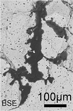
Figure 18. SEM image in back-scattered electron (BSE) mode of a lithium dendrite. Adapted with permission from Reference [136]. Copyright (2019) American Chemical Society.
Download figure:
Standard image High-resolution imageLLZO thin films have been prepared by using well-established deposition processes such as magnetron sputtering and pulsed laser deposition. However, these vacuum-based deposition techniques are unlikely to be used for scaled-up manufacturing due to their high cost and slow deposition rates [125, 135]. Although the deposited films have well-controlled thicknesses, they are usually amorphous, resulting in Li+ ionic conductivity values several orders of magnitude lower than those achieved for bulk LLZO samples. Crystallization of the deposited LLZO thin films is problematic, as the high temperatures required (> 900°C) cause Li volatilization from the material, resulting in changed stoichiometry [134]. Heat-treatment is even more problematic when LLZO electrolyte layers are prepared from crystalline LLZO ceramic particles, requiring even higher processing temperatures over long periods (several hours) to achieve satisfactory densification. Li loss is especially severe under these conditions for thin films because of their higher surface-to-volume ratios, resulting in the formation of secondary phases, mainly in the surface layers, due to extensive Li loss [137]. Due to the brittle nature of refractory materials, standalone LLZO thin film can be mechanically too weak to handle any post-sintering steps, such as polishing, to remove Li deficient surface layers, which is usually done in case of LLZO pellets. Thus, some special measures must be considered to counter the challenges described above for the development of a practical and economical processing method for LLZO thin films.
15.3. Advances in science and technology to meet challenges
Experience obtained from past studies regarding LLZO processing can be adapted for thin films. The issues related to carbonate surface impurities occurring during the processing of LLZO can be alleviated by using an inert environment and some additional heat-treatment, although it would probably result in increased manufacturing cost. The mechanical properties of self-supported LLZO thin films could be improved by using flexible composite electrolytes of ceramic particles embedded into an ionically conductive polymer network [138]. The advantage of ceramic+polymer composite layers is that they do not require heat-treatment; this would render any issues related to Li loss irrelevant. Another approach is to create a multilayered structure by co-sintering the LLZO thin film onto a thick, porous LLZO support, which would also act as, for example, an ionically conductive 3D scaffold for metallic Li electrode. This type of cell architecture provides a high interfacial surface area, permitting high operating current densities (10 mA cm−2) [139].
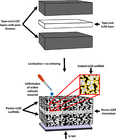
Figure 19. Fabrication of LLZO-based SSB by laminating and co-sintering the tape-cast layers, followed by integration of active electrode materials into the multi-layered LLZO architecture.
Download figure:
Standard image High-resolution imageHeat-treatment of an LLZO electrolyte can be optimized to fine-tune its microstructure, e.g. to minimize the amount of grain-boundaries and pores, which would otherwise contribute to the resistance of electrolyte, and serve as pathways for Li dendrite propagation. The most straightforward way to control Li content in the sintering environment would be the use of a sacrificial cover powder [140]. Graphite substrates/envelopes can be used for sintering LLZO tape-cast layers in non-oxidizing gas atmospheres because of their non-wetting behaviour [137]. The thickness of an LLZO electrolyte layer produced by tape-casting can be decreased down to 1 µm. This requires careful control over the starting powder (grain size and morphology), the rheological properties of the tape-casting slurry, and casting parameters. Dense particle packing in the cast tape helps to achieve high final densities under moderate thermal treatment conditions, while minimising time and cost. High density (99%) LLZO layers can be fabricated by using, for example, Li2O as a sintering aid [140]. A short heat-treatment duration ( 1 h) has proven sufficient to achieve tape-cast LLZO layers with a density of 95% and an ionic conductivity of > 1 S cm−1 at room temperature. In this case, the films were prepared from nanoparticles with adequate processing chemistry [137].
15.4. Concluding remarks
The commercialisation of SSBs requires well-established scalable processing for producing solid electrolyte thin films. Fabrication of thin films made from LLZO, one of the main candidates for electrolyte materials in future SSBs, presents some challenges in relation to processing. Several studies have previously focused on this matter, proposing different approaches to the issues related to the handling and heat-treatment of LLZO layers. The solutions recommended include composite electrolytes, multi-layered structures, strict control over the characteristics of starting powder and processing chemistry, and adequate sintering setups. Scalable tape-casting technique is currently the main candidate method for feasible fabrication of dense oxide electrolyte layers with thicknesses down to 10 µm. Future work needs to demonstrate the functionality of these tape-cast LLZO membranes in the actual SSB cells, with accompanying high performance.
Acknowledgments
This work was supported by the Faraday Institution [SOLBAT, grant No. FIRG007].
16. Thin-film solid-state batteries
Stephen J Turrell and Chris Grovenor
Department of Materials, University of Oxford, Oxford OX1 3PH, United Kingdom
The Faraday Institution, Quad One, Harwell Campus, OX11 0RA, United Kingdom
16.1. Status
Thin-film solid-state batteries are fabricated by the successive deposition of electrode and electrolyte layers, each less than 10 µm thick, using techniques such as magnetron sputtering, pulsed laser deposition (PLD), vacuum evaporation, chemical vapour deposition (CVD), or atomic layer deposition (ALD). The first true thin-film cell, reported by Sator in 1952, featured a PbCl2 electrolyte and Ag electrodes deposited by vacuum evaporation [141]. Interest in thin-film deposition grew with advances in solid-state batteries during the 1960s, driven by the need to minimise the contribution of low conductivity (∼ 10−7 S cm−1) electrolytes to overall cell impedance. The first thin-film cell containing lithium (Li/LiI/AgI) was reported in 1969 [142], and was followed by improvements to both electrode and electrolyte materials over the next two decades, including the introduction of the TiS2 intercalation cathode (∼ 2.45 V vs Li+/Li) and glassy electrolytes with ionic conductivities of ∼ 10−6 S cm−1 [143]. The steadily increasing energy densities and stabilities of thin-film cells, along with the rapid development of integrated circuit technology, drove efforts to fabricate a thin-film "microbattery" directly onto a microchip. Significant progress towards this goal was made in the 1990s at Oak Ridge National Laboratory with the development of a Li/lithium phosphorus oxynitride (LiPON)/lithium cobalt oxide (LCO) thin-film cell (figure 20) [144].
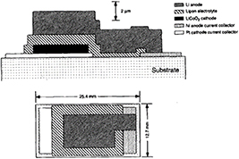
Figure 20. Schematic cross-sectional (top) and plan view (bottom) drawings of a Li/LiPON/LCO thin-film cell. Reprinted with permission from [4]. Copyright 1996, The Electrochemical Society.
Download figure:
Standard image High-resolution imageThis cell design was commercialised and remains the predominant thin-film system, owing to its relatively high voltage and ability to survive several thousand charging cycles before failure [145, 146]. Next-generation thin-film cells with higher energy and power densities have the potential to enable a host of new technologies, including implantable and wearable electronics, and 'Internet of Things' devices. As well as being key to microbattery production, thin-film cells offer several other benefits. These include a small volume fraction of inactive material due to the lack of binders and additives, low impedance interfaces, and the attainment of high-density layers with negligible defect concentrations at much lower temperatures than required by the ceramic processing techniques used to fabricate bulk cells [144, 146]. These attributes result in a high theoretical energy density, long cycle life and simple, low-cost construction. Nevertheless, improvements in cell design, materials and processing are required before large-scale commercialisation will be attractive.
16.2. Current and future challenges
Many of the challenges facing the development of thin-film batteries apply to all types of solid-state battery. Important examples include obtaining cathodes with higher potentials vs. Li+/Li, stabilising lithium metal anodes, and finding solid electrolytes with greater ionic conductivities and wider electrochemical stability windows [146]. Challenges specific to thin-film cells mostly relate to defining the links between processing, structure and performance, finding the optimum cell architecture for maximising power density and volumetric capacity, demonstrating the viability of large-scale manufacturing. Electrolyte materials with low ionic conductivities but other favourable attributes (such as outstanding cycling stability and resistance to short circuiting in LiPON, which has an ionic conductivity on the order of 10−6 S cm−1 at room temperature [144]) may be viable in thin-film form. Nevertheless, it would be desirable to produce thin films of materials with high ionic conductivity in the bulk, such as garnets based on Li7La3Zr2O12 (LLZO). Unfortunately, the room temperature ionic conductivities of garnet thin films are usually several orders of magnitude lower than the bulk values (10−7–10−6 S cm−1 rather than 10−4–10−3 S cm−1) [146]. Possible explanations include smaller grain sizes in thin films, lithium loss to the vapour phase during processing, and the creation of internal stresses during deposition. Most thin film cells suffer from low power densities and total capacities [147]. The absence of conductive additives and strain-absorbing fillers limits the cathode thickness that can be reached before the cell admittance and accessible capacity become unacceptably low. Furthermore, the flat cathode-electrolyte interface is a major lithium transport bottleneck; in conventional lithium-ion cells the liquid electrolyte penetrates the cathode, increasing the interfacial area and hence the energy available at high cycling rates. To be viable commercially, industrial-scale thin-film cell manufacturing must be both efficient and cost-effective. Techniques such as magnetron sputtering are used in the high-volume manufacture of functional thin films on touch screens and razor blades [148, 149], but little attention has been given to suitable mass production processes for thin-film batteries. Future thin-film cell development should focus on the optimisation of industrial deposition parameters and cell designs, since methods used in the laboratory may not be compatible with industrial processes.
16.3. Advances in science and technology to meet challenges
Thin-film deposition technology can create structures, and hence properties, that are not easy to achieve in bulk materials. For example, the amorphous structure of LiPON responsible for its outstanding cycling stability is formed at low temperatures by a simple magnetron sputtering process. The discovery of new amorphous electrolytes with the same mechanical stability as LiPON, but with higher ionic conductivities and wider electrochemical windows, should be an area of focus for future research. Garbayo et al [146] have already demonstrated the feasibility of producing amorphous garnet-type electrolytes with a degree of short-range ordering, dependent on the deposition temperature. The highest ionic conductivity was measured in films deposited at 300°C–more than 700°C lower than the typical sintering temperatures required for bulk garnet. With a similar ionic conductivity to that of LiPON, but a wider stability window, these films may perform better in cells containing high-voltage cathodes. In terms of cell design, thin-film deposition could allow the construction of many alternatives to the common planar structures. Architectures that maximise areal capacity and power density by increasing the cell layer area while keeping the cathode thickness and cell footprint area constant are of particular interest [147]. These designs belong to an emerging field of '3D thin-film batteries' which encompasses cells built on non-planar substrates. There are several promising processing routes for these cells: for example, a current collector can be deposited through a template to build up an array of nano/micro-rods onto which the subsequent cell layers are deposited (figure 21) [150]. Alternatively, photolithography and etching or 3D printing can be used to create a three-dimensional substrate, or the cell layers can be deposited into a preformed structure with high internal surface area, such as an aerogel or perforated membrane [147].
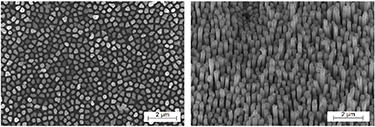
Figure 21. Top view (left) and side view (right) SEM micrographs of aluminium nanorods synthesised by pulsed electrodeposition through an alumina template which was subsequently dissolved away. Adapted with permission from [10]. Copyright (2009) American Chemical Society.
Download figure:
Standard image High-resolution image3D thin-film cells could present some manufacturing challenges since common deposition techniques such as magnetron sputtering may not be suitable for depositing uniform layers on a three-dimensional substrate [147]. ALD and electrochemical deposition have been reported to be more appropriate, owing to their non-directional, self-limiting deposition characteristics. A significant amount of research will be required to determine the optimum designs and deposition parameters for high performance three-dimensional thin-film cells.
16.4. Concluding remarks
Miniaturised electronic devices will underpin several technologies that promise to have a great societal impact. These devices will require safe, reliable, and energy-dense power sources. Thin-film solid-state batteries should be ideally suited to these applications, although several barriers to large-scale commercialisation currently exist. The overarching challenge is to improve our understanding of the processing-structure-properties relationships of thin-film cells, both at the materials and whole-cell levels. In terms of materials challenges, studying the ionic conduction mechanisms in amorphous electrolyte materials will aid the selection of appropriate candidates to succeed LiPON. Whole-cell challenges centre on internal cell interfaces and the need to maximise areal capacity without sacrificing power density. Relatively few investigations have been performed on 3D cell architectures; future studies must seek to achieve the optimum balance between cell performance and processability, and overcoming these challenges is likely to be the focus of thin-film cell research for the foreseeable future.
Acknowledgments
This work was supported by the Engineering and Physical Sciences Research Council ['Enabling next generation lithium batteries' EP/M009521/1] and the Faraday Institution ['All-Solid-State Batteries with Li and Na Anodes' FIRG007, FIRG008]. SJT acknowledges support from an EPSRC PhD studentship [project reference 2114670 related to EP/R513295/1].
17. X-ray imaging of solid-state batteries: challenges and opportunities
P R Shearing
The Electrochemical Innovation Lab, University College London, London WC1E 7JE, United Kingdom
The Faraday Institution, Quad One, Harwell Campus, OX11 0RA, United Kingdom
17.1. Status
The development of x-ray imaging tools for applications in materials science and engineering is well documented [151]. Of the pantheon of microscopy tools, x-ray microscopy provides unique benefits, in particular relating to its non-destructive and multi-scale capabilities. X-ray computed tomography (CT) provides the opportunity to image materials in three-dimensions, and due to the non-destructive nature of x-ray imaging, investigations can be extended into the fourth dimension, to explore the changes in materials over time, and in response to a range of environmental stimuli.
X-ray imaging is compatible with laboratory and synchrotron sources, the latter providing substantial enhancements in x-ray flux. In their recent review, Withers and Maire [151] catalogued a range of available x-ray tomography platforms. Whilst the benefits in temporal resolution for synchrotron sources are obvious, some laboratory tools provide competitive spatial resolution. It is possible to achieve sub-micron resolution by the implementation of optical architectures to focus the transmitted radiation, whilst scanning probe techniques and emerging techniques using ptychography and coherent diffraction imaging are also capable of providing further enhancements to spatial resolution. In spite of these advantages, the inherent resolution of x-ray imaging tools does not match those typically available from the suite of electron techniques, and consequently they are most powerful as part of a correlative microscopy toolbox [152].
The invention of x-ray computed tomography for medical applications earned its pioneers the Nobel Prize in 1979; by the early 1980 s, these techniques were being actively applied to applications in materials engineering. However, it was not until much later that the first examples of x-ray tomography for applications in battery science and engineering emerged. Indeed, it was not until 2010 that images with sufficient resolution to characterise Li-ion battery electrode microstructure were published [153]. The succeeding decade has seen the widespread adoption of tomographic tools for the study of battery materials and devices, which include multi-scale and in situ studies spanning a range of chemistries, and have been successfully incorporated into image based models. These achievements are summarised in a number of comprehensive, recent review articles [154–156].
17.2. Current and future challenges
The application of x-ray imaging to understand solid state batteries provides a significant opportunity, to be summarised in the next section. First, we will consider the hurdles that must be overcome for its effective implementation.
In x-ray absorption imaging, the primary means of contrast generation is through attenuation differences, predominantly arising through electron density differences in the constituent materials. This is described by the Beer–Lambert law, from which we can derive a characteristic attenuation length for different materials. Solid state batteries commonly comprise a Li-metal anode with a dense ceramic electrolyte; for example, theoretical predictions from the Center for x-ray Optics database for the attenuation length of these materials at 20 keV incident beam energy are 117, 307 µm for Li and 590 µm for LLZO.
This marked difference in the attenuation length of these materials gives rise to the first challenge: the large density difference between Li and LLZO demands different requirements in the incident x-ray beam. The high mass density of the ceramic electrolyte requires high x-ray energy to provide sufficient transmission, whilst the limited x-ray interaction with metallic Li requires the use of lower energies and alternative imaging modalities.
For some time, x-ray imaging of metallic Li was widely believed to be intractable. However, in recent years, the development of phase contrast imaging modalities has enabled their study. Phase contrast imaging relies not only on the absorption of incident X-rays, but also their phase shift; combined with phase retrieval algorithms, this imaging modality provides the flexibility to image samples with characteristically low densities. The first example of imaging metallic Li was presented by Harry et al [159] in their study of metallic electrode growth through polymer electrolytes, and shortly thereafter by Eastwood et al [160], who studied the geometric nature of dendrite growth in liquid electrolyte systems. Other examples include in situ imaging of metallic Li electrodes as a function of cycle life [160, 161].
Whilst initially, solid electrolytes were thought to block the passage of dendrites during stripping and plating, a growing body of evidence shows that this problem persists above critical current densities. The next major challenge for imaging concerns the multi-length scale nature of the 'dendrite' problem: the nucleation of Li plating is expected to occur at microscopic length scales, whilst the propagation of dendrites leading to final short circuit will have macroscopic effects. Moreover, these events may be 'buried' deep inside the cell. Consequently, there is a careful balance to strike between the sample volume analysed, and the resolution required; this tension is particularly acute for this inherently hierarchical problem.
17.3. Advances in science and technology to meet challenges
The growth in maturity of x-ray imaging technologies, and their flexibility as part of a portfolio of correlative characterisation techniques, provides a compelling opportunity to enhance the development and commercialisation of solid state batteries. Whilst historically, the optimisation of battery technologies has been achieved through primarily empirical means, the availability of multi-scale 3D imaging tools provides a toolbox for the quantitative evaluation of materials and devices, which can readily be fed back to the design process.
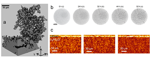
Figure 22. Recent examples from the literature show the possibilities of applying advanced x-ray imaging to explore metallic electrodes and solid state electrolytes. (a) The growth of metallic Li imaged by phase contrast x-ray imaging (reproduced from [157] with permission from the Royal Society of Chemistry; (b) The growth of cracks in solid state electrolytes (reprinted with permission from [158], Copyright 2019 American Chemical Society); (c) The evolution of the metal/ceramic interface (reprinted with permission from [4], Copyright 2019 Springer Nature).
Download figure:
Standard image High-resolution image
It is increasingly possible to rapidly screen batteries and their constituent materials to evaluate new materials and device engineering approaches, by providing rational design criteria and quantitative comparisons. In recent years, there has been significant improvement in the throughput of x-ray imaging systems, through improvements to hardware, imaging protocols, and reconstruction algorithms. Consequently, it may become tractable to routinely employ x-ray CT in the cell production process, as well as the materials supply chain, providing more robust quality control.
Owing to the non-destructive nature of x-ray imaging, its capacity to explore microstructure evolution in response to a range of environmental conditions is unparalleled. In the field of solid state batteries, there is an emerging opportunity to explore the changes in electrode and electrolyte morphology; for example, to track the growth of metallic dendrites leading to short circuit, or changes in the electrode/electrolyte interface. In combination with the development of appropriate theory and modelling tools, this provides a toolbox for mechanistic studies with unprecedented insight.
Whilst the use of x-ray imaging in studies of solid state batteries is at a relatively nascent stage, finally we consider some examples from the literature: McDowell et al have used x-ray CT to evaluate the mechanical stresses arising at the electrode/electrolyte interface which drive degradation of the battery [158], and similarly Bruce et al have used in situ x-ray CT to explore the interface evolution, related to the critical current density for dendrite propagation [4]. Elsewhere, the evolution of connected porosity in garnet electrolytes has been explored [162], although critical challenges persist in the discrimination between electrolyte voids and deposited lithium. These tools are increasingly being applied to emerging chemistries, including solid-state Li-sulfur [163], and Na batteries [164], indicating the growing role of x-ray imaging to accelerate the development and commercialisation of next generation batteries.
17.4. Concluding remarks
The emergence of x-ray tomography for applications in battery science and engineering has revolutionised our understanding of the performance/microstructure relationship for a range of materials and devices. With increasing demands on batteries across a range of applications, the drive towards post Li-ion chemistries is accelerating. In this context, x-ray imaging has a significant role to play in facilitating the commercialisation of these devices (including solid state batteries), by providing rational design guidelines for rapid evaluation and optimization.
Acknowledgments
PRS acknowledges the support of the Faraday Institution [SOLBAT, grant No. FIRG007] and The Royal Academy of Engineering.