

Abstract
The incorporation of inorganic nanofillers into polymeric matrices represents an effective strategy for the development of smart coatings for corrosion protection of metallic substrates. In this work, wet-jet milling exfoliation was used to massively produce few-layer hexagonal boron nitride (h-BN) flakes as a corrosion-protection pigment in polyisobutylene (PIB)-based composite coatings for marine applications. This approach represents an innovative advance in the application of two-dimensional (2D) material-based composites as corrosion protection systems at the industrial scale. Although rarely used as an organic coating, PIB was selected as a ground-breaking polymeric matrix for our h-BN-based composite coating thanks to its excellent barrier properties. The optimization of the coating indicates that 5 wt.% is the most effective h-BN content, yielding a corrosion rate of the protected structural steel as low as 7.4 × 10⁻⁶ mm yr−1. The 2D morphology and hydrophobicity of the h-BN flakes, together with the capability of PIB to act as a physical barrier against corrosive species, are the main reasons behind the excellent anticorrosion performance of our composite coating.
Export citation and abstract BibTeX RIS

Original content from this work may be used under the terms of the Creative Commons Attribution 4.0 license. Any further distribution of this work must maintain attribution to the author(s) and the title of the work, journal citation and DOI.
1. Introduction
Metallic corrosion is a significant problem that leads to enormous economic losses [1]. It can cause critical structural failures with dramatic consequences for both humans and the environment [2]. The protection of metallic structures has been investigated over the years through a wealth of research on protective coatings [3] and corrosion inhibitors [4]. Among the different materials for this purpose, organic ones, including polymers, have attracted growing attention due to their excellent processability, efficiency to hinder the corrosive species from reaching the metal surface and the possibility to colour the metal surfaces [5]. The performance and durability of anticorrosive coatings are determined by: (i) intrinsic factors, such as the composition [6], curing [7] and thickness [8] of the coating, (ii) the engineering of the coating-substrate interface [9], requiring the identification of suitable resins and pre-treatments of the substrate [10] to provide optimal coating adhesion properties [11], and (iii) environmental conditions, e.g. seawater, acidic media, exposure to heat or irradiation [12].
Various polymeric materials have been investigated to develop protective coatings against metal corrosion, i.e. polyvinyl butyral [13], polydimethylsiloxane [14], polyurethane [15], polyaniline [16], polypyrrole (PPy) [17] and polythiophene [18]. Among them, polyisobutylene (PIB) is a versatile material that has received increasing attention since its invention dated to 1930 [19] and found a wide range of applications, such as adhesives [20], sealants [21], multiblock copolymeric materials [22], personal care products [23] and fuel additives [24]. More in detail, PIB has demonstrated unique air tightness, gas impermeability and excellent weathering resistance, as well as good flexibility even at mild sub-ambient temperatures [19]. These features merged with its low cost, innocuousness and the possibility to tune its distinctive properties by varying the molecular weight, make PIB an ideal candidate to formulate polymeric coatings for metal protection against corrosion. Despite the advantages provided by PIB and other polymeric coatings in the field of corrosion protection, several challenges must be overcome to attain reliable and efficient protective systems for long-term application [25], including chemical degradation under environmental conditions [26].
To address these issues, the addition of fillers into the polymeric matrix has been considered as an effective strategy to realize composites with superior barrier performance compared to pristine polymers [27]. For example, micro-sized fillers can be embedded into the polymeric structure to produce composite coatings. However, the high amount of such micro-fillers (about 60 vol.%) required to obtain successful anti-corrosion properties negatively affects the adhesion of the coating to the substrate, while increasing the density of the composite [28]. Instead, due to their high surface area and tuneable surface-to-volume (aspect) ratio, a low amount (i.e. <2 vol%) of nano-sized fillers can be effectively incorporated into polymeric coatings to improve the anticorrosion properties [29]. Among the nanofillers [30], graphene and hexagonal boron nitride (h-BN) are two-dimensional (2D) materials that have been widely investigated in protective coatings due to their excellent barrier properties, chemical resistance, impermeability and thermal stability [31]. However, graphene stimulates the galvanic corrosion of non-noble metal substrates [32] as a consequence of its electrical conductivity (charge carrier mobility = 105 cm2 V−1 s−1 [33]) and nobility in the galvanic (electro potential) series [34]. Graphene-polymer composites often yielded insufficient protection efficiency for corrosion protection of metals over long-term operation [35, 36]. In contrast, 2D h-BN is an electrical insulator with a wide band gap of ∼5.5 eV [37, 38], which prevents undesirable galvanic coupling effects [39].
In this work, we will focus on the implementation of h-BN flakes as fillers in polymer-based composites for corrosion protection. In this regard, h-BN is a layered material consisting of atomically thin layers of covalently bonded boron and nitrogen atoms stacked together by van der Waals interactions [40]. Thanks to its low cleavage energy (32.8 meV atom−1 to obtain the monolayer) [41], bulk h-BN crystals can be exfoliated in their high-specific surface-area (SSA) 2D forms (SSA of an h-BN monolayer is 1488 m2 g−1) [42], including single-/few-layer flakes [37, 38, 43], which have been applied to passivate metallic surfaces from water thanks to their hydrophobic nature [44]. In addition, the delocalised dense cloud of overlapping π-orbitals of h-BN generates a physical barrier against molecules or ions, leading to a distinctive atomical impermeability [45]. The latter is crucial in providing the corrosion-protecting role of h-BN, as shown for thin films and monolayer h-BN that protected stainless steel [46] and copper [47] against corrosion in marine environments. Nevertheless, the application of h-BN monolayers as anticorrosive coatings faces several challenges, for example, highly demanding conditions for getting a successful direct growth on surfaces of desired metals (e.g. steel) [48], failure of ultra-thin coatings [49], poor adhesion or delamination [50], friction-induced damage [51] or problems related with the upscaling of monolayer growth techniques (e.g. the difficulty of obtaining defect-free nanosheets [52, 53] or achieving large-scale homogeneity [54]) from laboratory to industry [55]. To overcome these limitations, liquid-phase exfoliation (LPE) methods [56] have been established as eligible techniques to scale up the production of 2D h-BN in liquid media [57], providing dispersions that can be directly used to formulate advanced composites with polymers by solution blending methods [58]. Therefore, LPE-produced h-BN flakes have been successfully incorporated into different matrices [39, 59], providing physical barriers against corrosive species while exhibiting mechanical reinforcing properties. Among the LPE methods, wet-jet milling (WJM) exfoliation can be considered an ideal candidate since it enables the production of defect-free and high-quality 2D crystal dispersions on a large scale using the shear forces generated by the recombination of high-speed solvent jet streams to drive the exfoliation of layered crystals [57, 58]. The main advantage of WJM compared to other LPE techniques is the processing time of the sample, i.e. the passage of the processed dispersion through the nozzle, which is reduced to a fraction of a second, instead of hours in a sonic bath [60] or shear exfoliation systems [61]. Thus, the WJM technology opens the way for the industrial production of high-quality 2D materials for commercial applications, including reinforcement fillers and polymeric composites [62]. Currently, the h-BN production rate is 1 kg d−1 for a single WJM apparatus, permitting 5200 kg yr−1 production of the composite optimized in this work. This amount of composite will permit to protect a metal surface area close to 100 000 m2.
This work investigates h-BN flakes, produced through the WJM method in an industrial plant, as functional anticorrosive fillers into polymeric PIB matrix to yield h-BN/PIB composites with different h-BN contents. Once cast on structural steel substrates, the anticorrosion properties of the as-produced composites were evaluated in a 3.5 wt.% NaCl aqueous solution, yielding an optimized coating, which shows excellent performance and durability against corrosion in marine environments.
2. Experimental
2.1. Materials
PIB was provided in the form of Oppanol® N80 (average molecular weight—Mv—800 000) by BASF Italia S.p.A. Toluene (purity >99.7%) was supplied by Merck. N-methyl-2-pyrrolidone (NMP) was provided by ThermoFisher Scientific. Few-layer h-BN flakes were produced in the industrial plant of BeDimensional S.p.A. as previously described in our works [62, 63].
2.2. Preparation of h-BN/PIB composite coatings
The production procedure of the h-BN/PIB composites was carried out as follow. Firstly, solid PIB was dissolved in toluene with a PIB/toluene weight ratio of 1:8 and stirred for 12 h at 800 rpm and 80 °C until a homogeneous solution was obtained. Then, different mass loadings of WJM-produced h-BN flakes were added into the PIB solution followed by mixing in a Thinky ARE-250 Mixing and Degassing Machine (planetary centrifugal mixer) at 1000 rpm for 5 min to produce h-BN/PIB composite resins with h-BN weight percentage (wt.%) of 2.5, 5, 10 and 20. The as-produced resins were deposited onto cylindrical substrates of structural steel (S355 grade) by doctor blading. Finally, the resulting coatings were dried at room temperature for 1 h, followed by 15 h at 60 °C to evaporate the residual solvent. The thickness of the resulting pristine PIB or h-BN/PIB coatings onto the S355 steel substrates was measured with a Trotec BB20 thickness magnetic induction-based measurement system.
2.3. Material and coating characterisation
The morphological properties of the WJM-produced h-BN flakes were studied through transmission electron microscopy (TEM) measurements, which were carried out with a JEOL Jem-1011 (Jeol) transmission electron microscope operated at an acceleration voltage of 100 kV. The samples were prepared by drop-casting the produced h-BN dispersions in NMP at a 1:50 weight ratio onto ultrathin C-film on holey carbon 400 mesh Cu grids (Ted Pella Inc). The grids were stored under vacuum at room temperature to remove the solvent residues. The lateral size of the h-BN flakes was measured from TEM images, and the statistical data analysis was performed using OriginPro 2020 on 100 flakes, fitting the data with a log-normal distribution. The thickness of the h-BN flakes and the roughness of the coatings with different h-BN contents were analysed by atomic force microscopy (AFM) measurements performed with an NX10 AFM (Park System) in non-contact mode using a non-Contact Cantilever PPP-NCHR 10 M (resonance frequency ∼330 kHz, force constant 42 N m−1). The samples were prepared by drop-casting the WJM-produced h-BN dispersions diluted 1:100 in isopropyl alcohol onto mica sheets (Ted Pella, Inc.), followed by heating at 250 °C for 20 min to remove the solvent residues. The images were collected on different areas of 35 × 35 µm2 (512 × 512 data points), with a scan rate of 0.30 Hz and keeping the working set point at ∼6 nm. Gwyddion (64 bit) software was used to process the images and the height profiles, while the statistical data analysis was carried out on 100 flakes using OriginPro 2020. Thermogravimetric analysis (TGA) measurements were carried out using a TGA Instruments STD650 under an N2 atmosphere (flow rate: 100 ml min−1) and a temperature ramp of 10 °C min−1 from 30 °C to 700 °C. The x-ray diffraction (XRD) patterns were recorded on a PANalytical Empyrean x-ray diffractometer equipped with a 1.8 kW CuKα ceramic x-ray tube, PIXcel3D 2 × 2 area detector and operating at 45 kV and 40 mA. The diffraction patterns were collected in air at room temperature using parallel-beam geometry and symmetric reflection mode. The scanning electron microscopy (SEM) measurements were acquired using a JEOL JSM-6490LA SEM analytical (low-vacuum) instrument with a thermionic electron gun equipped with a tungsten source after coating the samples with 10 nm of gold layer. The hydrophobicity of the composites was investigated by contact angle (CA) measurements, imaging a 10 μl water drop deposited on the different composites with an OSSILA L2004A1 CA goniometer. The molecular structure of the coatings was evaluated by Fourier-transform infrared (FTIR) analysis. Thin films (thickness of ∼4 μm) of the different composites were deposited by the doctor blading technique on CaF2 substrates (Crystran). The films were characterised in transmission mode using a PerkinElmer Frontier FTIR spectrometer equipped with an N2 flow for purging the chamber during the measurements. All the spectra were recorded from 4000 to 600 cm−1 with a 4 cm−1 resolution, accumulating 128 scans to improve the signal-to-noise ratio. A clean CaF2 substrate was used as a blank. Raman measurements were carried out using a Renishaw InVia micro-Raman spectrometer with a 100× objective (numerical aperture of 0.85). An excitation wavelength of 514.5 nm was used with an incident power of less than 1 mW to avoid sample overheating. Optical microscopy images of the steel substrate before and after the long-term immersion test were obtained using a Leica optical microscope with a 100× objective (N.A. 0.85).
2.4. Electrochemical characterization
Electrochemical measurements were carried out using a BioLogic VMP3 Multichannel Potentiostat in a three-electrode 1L electrochemical cell at room temperature in a 3.5 wt.% NaCl aqueous solution, following the procedure described in ASTM G5-14 standard. A KCl-saturated Ag/AgCl radiometer Analytical REF201 Red Rod Reference Electrode (Biologic) was used as the reference electrode, whereas a graphite rod was used as the counter electrode. The standard working electrode assembly consisted of a cylindrical sample of steel substrate (0.785 cm2 area) coated by PIB or the h-BN/PIB composites, drilled and tapped with a 3-48 UNC thread, and screwed onto the support rod. A polytetrafluoroethylene compression gasket ensures a leak-free seal. The open-circuit voltage (OCV) was monitored for 30 min, after which potentiodynamic anodic polarisation measurements were acquired with a scan rate of 10 mV min−1. The corrosion performance of the coatings was investigated by potentiodynamic anodic polarisation measurements and their Tafel analysis, as described in the ASTM G5-14 standard, for the determination of the corrosion current (icorr) and the corrosion potential (Ecorr) of metal [64, 65]. The linear values of polarization resistance (Rp) were calculated following the ASTM G59-97 protocol from the slope of the polarisation curve at the Ecorr point [66], i.e.:
The corrosion rate (CR) value was calculated from icorr by the Faraday law:
in which CR is the corrosion rate (in mm yr−1), K is a constant with a value of 3.27 × 10⁻³, Weq is the equivalent weight of iron in ferrous compounds (27.9 g eq−1), icorr is the corrosion current density (in μA cm−2) and D is the density of steel (7.85 g cm−3) [67]. The inhibition efficiency (ηp) values of the composites are calculated from icorr by the following equation:
in which i0 corr and icorr are the corrosion current densities in the absence and presence of inhibitors, respectively [68].
Electrochemical impedance spectroscopy (EIS) measurements were carried out in potentiostatic mode at OCV with an AC sinusoidal amplitude of 10 mV over a 0.1 Hz–200 kHz frequency range, following the ASTM G106-89 standard. Cyclic potentiodynamic polarization measurements were conducted at 0.6 V h−1, following the ASTM G61-86 standard guidelines. A long-term immersion test in 3.5 wt% NaCl aqueous solution was conducted for continuous 1000 h following the ASTM G31-72 protocol.
3. Results and discussion
3.1. Characterisation of h-BN flakes
The exfoliated h-BN flakes were produced through WJM exfoliation of bulk h-BN crystals, as described in our previous work [62, 63]. This technique allows the massive production of defect-free and high-quality 2D crystal dispersions, showing a material production rate of up to 1 kg d−1 on a single WJM apparatus [62, 63]. The as-produced h-BN flakes were characterised by TEM and AFM measurements to investigate their morphological properties. The inset to figure 1(a) shows a representative TEM image of h-BN flakes (additional TEM images are shown in supporting information, figure S1) exhibiting rounded edges and having lateral sizes ranging from 25 to 1000 nm approximately. The size distribution follows a log-normal shape, peaking at 105.2 nm (figure 1(a)). The inset to figure 1(b) displays an AFM image of representative h-BN flakes (additional AFM images are shown in supporting information, figure S2).

Figure 1. (a) Statistical analysis of the lateral size of h-BN flakes obtained from TEM images (inset: TEM image of representative h-BN flakes). (b) Statistical analysis of the thickness of h-BN flakes obtained from AFM images (inset: AFM image of representative h-BN flakes). (c) TGA analysis of exfoliated h-BN powder (red solid line) versus bulk h-BN (red dashed line). (d) XRD patterns of bulk and exfoliated h-BN (inset: enlarged view of crystallographic (002) plane region).
Download figure:
Standard image High-resolution imageThe statistical analysis of the flake thickness indicates that these data follow a log-normal distribution peaked at 4.3 nm, with more than 75% of the flakes showing thickness lower than 20 nm (figure 1(b)). Considering the experimental thickness of an h-BN monolayer (0.09 nm) [69] and an interlayer distance of 0.33 nm [70], the AFM data analysis suggests that the exfoliated h-BN sample mainly consists of few-layer (⩽10) h-BN flakes. The solvent residues in the produced h-BN flakes were determined by TGA analysis. As shown in figure 1(c), a negligible amount of water and NMP (0.6% and 0.8 in wt.%, respectively) remained in the dried exfoliated h-BN powder. The comparison of the TGA analysis of exfoliated h-BN with bulk h-BN demonstrates that the solvent used for the WJM process is effectively removed in the exfoliated h-BN powder. The crystalline structure of the exfoliated h-BN and the starting bulk material was determined by XRD, and the results are shown in figure 1(d). The XRD pattern of exfoliated h-BN reveals a highly crystalline structure, with a characteristic intense peak at 26.7° corresponding to the crystallographic (002) plane of BN [71]. If this peak is compared to the peak of bulk h-BN, it can be seen that both have a similar diffraction angle and shape, indicating that the procedure of exfoliation did not change the crystalline structure of the starting material. The weak peaks observed in both samples at 2θ values of 41.6°, 43.9°, 55.1° and 76.0° correspond to the crystallographic planes of (100), (101), (004) and (110), respectively [72].
3.2. Characterisation of h-BN/PIB composites
The h-BN flakes were embedded into PIB by varying their content from 2.5 to 20 wt.% with respect to PIB, following the method described in section 2.2. The resulting resins were cast onto structural S355 steel substrates, as depicted in figure 2, yielding coatings with a measured average thickness of 58.4 ± 6.8 μm. Based on their h-BN content, the resulting composite coatings are named hereinafter h-BN/PIB 2.5%, h-BN/PIB 5%, h-BN/PIB 10% and h-BN/PIB 20%. An h-BN-free pristine PIB coating was also produced as a reference sample.
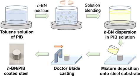
Figure 2. h-BN/PIB composite formulation and deposition on structural steel substrates.
Download figure:
Standard image High-resolution imageThe morphology of the as-produced h-BN/PIB composites with different h-BN contents was analysed by SEM imaging and compared with the one of pristine PIB. The SEM image of pristine PIB (figure 3(a)) shows a homogenous polymeric structure free of fillers, whereas the SEM images of the h-BN/PIB composites (figures 3(b)–(e)) reveal that the incorporated h-BN flakes are homogeneously distributed within the polymeric matrices in all the composites with different h-BN contents. More specifically, no agglomeration of h-BN flakes is observed anywhere in the polymeric structure, reflecting the successful dispersion of the 2D h-BN nanofillers obtained with the method described in figure 2. The thermal stability of pristine PIB and h-BN/PIB composites was investigated by TGA. Figure 3(f) displays the TGA curves of the different coatings. All of them exhibited similar thermal behaviour, undergoing an abrupt weight loss at around 340 °C due to the decomposition of the PIB matrix. After 430 °C, the weight stabilizes at a constant value, which corresponds to the final residual weight.

Figure 3. SEM images of (a) pristine PIB, (b) h-BN/PIB 2.5%, (c) h-BN/PIB 5%, (d) h-BN/PIB 10%, and (e) h-BN/PIB 20% composites. (f) TGA curves for pristine PIB and h-BN/PIB composites as a function of temperature, measured in N2 atmosphere. Inset: TGA curve at 760 °C–800 °C region, showing the mass residues of each sample.
Download figure:
Standard image High-resolution imageTable 1 shows the values of the temperature at which the weight loss is 10% (T−10%) and 50% (T−50%), which are similar for all the samples, suggesting that the thermal stability of the composites is not affected by the presence of h-BN flakes. The residual weight values approximately correspond to the h-BN weight content in the different composites.
Table 1. Parameters obtained from the TGA analysis for pristine PIB and h-BN/PIB composites.
| Sample | T−10% (°C) | T−50% (°C) | Residual weight (%) |
|---|---|---|---|
| PIB | 359.1 | 389.1 | 0.01 |
| h-BN/PIB 2.5% | 375.9 | 401.0 | 3.27 |
| h-BN/PIB 5% | 365.4 | 391.8 | 6.04 |
| h-BN/PIB 10% | 381.9 | 407.6 | 10.93 |
| h-BN/PIB 20% | 372.1 | 400.2 | 21.05 |
The roughness of the coating surface has a significant influence on the coating hydrophobicity, which is a crucial factor in regulating the final anticorrosion performance [73]. The dependence of the coating roughness on the h-BN content was determined by AFM measurements. As shown in figure 4(a), the pristine PIB sample exhibits a smooth surface with a root mean square (RMS) roughness value of 1.2 nm in an area of 35 × 35 μm2. In the case of the h-BN/PIB 2.5% composite, the RMS roughness increases to 10.9 nm due to the occasional presence of h-BN flakes on the coating surface. The surface roughness further increases with raising the h-BN content in the h-BN/PIB 5%, h-BN/PIB 10% and h-BN/PIB 20%, exhibiting RMS roughness values of 41.4, 60.6 and 186.5 nm, respectively. Figure 4(c) shows the plot of the RMS roughness of the coating versus the h-BN content, evidencing a linear correlation between the h-BN content and the surface roughness of the composite coating. In this context, the influence of the h-BN content on the water wettability of the h-BN/PIB composite coatings was studied by water CA measurements. High CA values (>90°) entail superior hydrophobicity, which in turn reduces the penetration of the electrolyte through the coating hindering the diffusion of the electrolyte into the pores or cracks [73]. Figure 4(b) displays images of water drops deposited on the surfaces of the different composite coatings, whereas figure 4(d) shows the measured CA values plotted versus the h-BN content of the coating. Pristine PIB exhibited a CA of 88.3 ± 0.4°, close to the angle corresponding to a hydrophobic material (90°). The incorporation of h-BN flakes into PIB increases the CA beyond 90°. This trend can be ascribed to the presence of hydrophobic h-BN flakes [74, 75]. The h-BN/PIB 10% composite has shown the highest CA (100.5° ± 0.5°), while the increase of h-BN content up to 20 wt.% causes a decrease in the measured CA to 96.6° ± 0.5°. This last behaviour can be attributed to the aggregation of the h-BN flakes in the h-BN/PIB 20% coating, as indicated by the AFM analysis. Consequently, obtaining highly hydrophobic surfaces entails not only a sufficient h-BN content in the composite (e.g. between 2.5 and 15 wt.%) but also a homogenous dispersion of the h-BN flakes on the coating surface. Overall, we observed that h-BN/PIB composites with intermediate h-BN contents (e.g. 5 and 10 wt.%) yield the highest hydrophobicity, suggesting an improvement of the barrier properties against the diffusion of the electrolyte through the protective coating. The integration of h-BN flakes into the PIB matrix was evaluated by FTIR in the wavelength range between 4000 and 600 cm−1. The FTIR spectra measured for the different samples are displayed in figure 4(e). In the PIB spectrum, the characteristic bands appearing at 2961 cm−1 and 2916 cm−1 correspond to asymmetric stretching of CH3 and CH2, respectively [76]. The peak at 1471 cm−1 is attributed to the CH2 groups [76] or –CH bending [77], whereas the double peak at 1389 cm−1 and 1361 cm−1 can be assigned to CH3 symmetric bending [76]. The peak at 1231 cm−1 is attributed to C–H bending, while the weak peaks at 949 cm−1 and 923 cm−1 correspond to C=C bending due to small amounts of non-polymerised isobutylene [78].
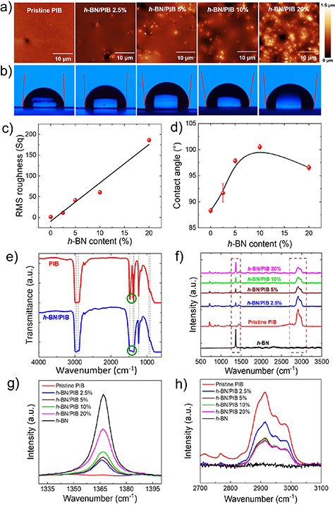
Figure 4. (a) AFM images and (b) water contact angle measurements of pristine PIB, h-BN/PIB 2.5%, h-BN/PIB 5%, h-BN/PIB 10% and h-BN/PIB 20%. (c) Plot of measured RMS roughness of the investigated coatings versus their h-BN content, showing the corresponding B-spline fitting. (d) Plot of water contact angle was measured for the investigated coatings versus their h-BN content, showing the corresponding B-spline fitting. (e) FTIR spectra of pristine PIB and a representative composite coating (h-BN/PIB 5%). Raman spectra of pristine PIB and h-BN/PIB composites with different h-BN content at (f) full range, (g) 1330–1400, and (h) 2700–3100 cm−1 regions, using an excitation wavelength of 532 nm.
Download figure:
Standard image High-resolution imageThe FTIR spectra of h-BN/PIB coatings exhibit differences in the region between the peaks at 1471 cm−1 and 1361 cm−1 compared to the PIB spectrum. In particular, the additional wide band overlapped to PIB peaks can be associated with the in-plane ring B–N stretching vibration (Eu mode) of h-BN at 1396 cm−1 [79]. These results further confirm the effective incorporation of the h-BN flakes into the polymeric matrix. In addition, Raman spectra were also acquired for pristine PIB and all the h-BN/PIB composites to complement the previous measurements, and the results are shown in figure 4(f). The pristine PIB Raman spectra displayed in figure 4(f) reveal a wide peak in the 2810 and 3060 cm−1 region with a maximum intensity at 2914 cm−1 as the main feature, which corresponds to the combination of symmetric and asymmetric carbon–hydrogen modes [80]. In addition, other minor peaks can be observed, especially those appearing at 717 cm−1 and 925 cm−1, corresponding to the methylene rocking mode, γr(CH2) [80], and out-of-plane CH deformation [81], respectively. In the pristine h-BN and h-BN/PIB composites spectra, a sharp peak at 1365 cm−1 can be observed, which is ascribed to the E2g phonon mode characteristic of h-BN [82]. This peak is analysed in figure 4(g), being absent in the pristine PIB curve, but gradually increases in intensity in the h-BN/PIB composites as the h-BN content rises. The wide peak at 2914 cm−1 characteristic of the PIB spectra previously mentioned, is shown in figure 4(h). It is seen that it reaches the maximum intensity for pristine PIB, whereas it decreases for the h-BN/PIB composites as the h-BN content increases up to 5 wt.%, remaining nearly constant beyond this value.
3.3. Anticorrosion performance of h-BN/PIB composites
The characteristic parameters that define the corrosion performance of the coatings can be determined by potentiodynamic anodic polarisation measurements and their Tafel analysis, following the ASTM G5-14 and ASTM G59-97 standards, as described in section 2. Figure 5(a) shows the anodic polarisation curves measured for the investigated h-BN/PIB composite coatings, pristine PIB coating and bare structural steel substrate without any coating. The most relevant metrics calculated from these plots are listed in table 2.
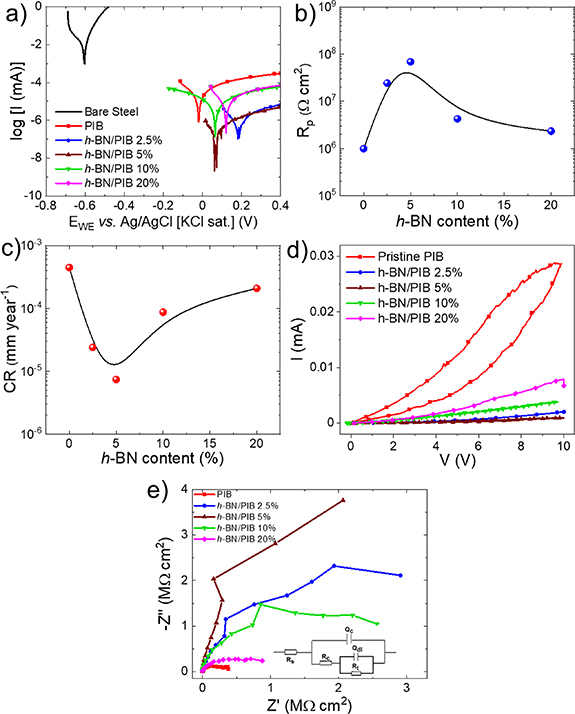
Figure 5. (a) Anodic polarisation curves (Tafel plots) of pristine PIB- and h-BN/PIB composite-coated structural steel. The Tafel plot measured for uncoated structural steel is also shown for comparison. (b) Measured Rp and (c) calculated CR measured for pristine PIB- and h-BN/PIB composite-coated structural steel versus h-BN content, showing the corresponding B-spline fitting. (d) Cyclic voltammograms of pristine PIB- and h-BN/PIB composite-coated structural steel. (e) Nyquist plots of pristine PIB- and h-BN/PIB composite-coated structural steel (inset: equivalent circuit diagram of coated structural steel substrates).
Download figure:
Standard image High-resolution imageTable 2. Electrochemical parameters of bare steel, pristine PIB and h-BN/PIB composite coatings with different h-BN contents, obtained from the Tafel analysis.
| Sample | Ecorr (V) | icorr (μA cm−2) | Rp (Ω cm2) | CR (mm yr−1) | ηp (%) |
|---|---|---|---|---|---|
| Bare steel | −0.604 | 4.8 × 101 | 1.3 × 10³ | 5.6 × 10⁻¹ | N/A |
| PIB | −0.020 | 3.9 × 10⁻² | 9.9 × 10⁵ | 4.5 × 10⁻⁴ | 99.921 |
| h-BN/PIB 2.5% | 0.187 | 2.1 × 10⁻³ | 2.4 × 10⁷ | 2.4 × 10⁻⁵ | 99.996 |
| h-BN/PIB 5% | 0.072 | 6.4 × 10⁻⁴ | 6.9 × 10⁷ | 7.4 × 10⁻⁶ | 99.999 |
| h-BN/PIB 10% | 0.065 | 7.5 × 10⁻³ | 4.3 × 10⁶ | 8.7 × 10⁻⁵ | 99.985 |
| h-BN/PIB 20% | 0.121 | 1.8 × 10⁻² | 2.3 × 10⁶ | 2.1 × 10⁻⁴ | 99.963 |
All the coatings protect the bare structural steel against corrosion. More in detail, the measured Ecorr of structural steel shifts from −0.604 V versus Ag/AgCl in bare steel to values ranging between −0.020 and 0.187 V, indicating the protective role of the polymeric coatings on the metallic surface. Importantly, h-BN/PIB composite coatings exhibit Ecorr higher than pristine PIB, reflecting the additional anticorrosion properties of the coating upon the incorporation of h-BN flakes. However, the Ecorr of h-BN/PIB composite coatings varies randomly with the h-BN contents. Differently, icorr decreases as the h-BN content rises until reaching a minimum of 6.4 × 10⁻⁴ μA cm−2 for the h-BN/PIB 5%. By further increasing the h-BN content above 5 wt.%, icorr increases. A similar behaviour for icorr has been previously reported for a PPy-intercalated graphene anti-corrosion system, in which the addition of a proper amount of graphene (0.5 wt.% with respect to polymer) into a PPy matrix reduced the intrusion of corrosive species, whereas an excessive amount of graphene (>0.5 wt.%) caused the formation of aggregates acting as local defects of the coating [83]. As shown in the plot of Rp versus h-BN (figure 5(b)), the h-BN/PIB 5% composite exhibited the maximum Rp value of 6.9 × 10⁷ Ω cm2.
Figure 5(c) shows the CR values calculated for each structural steel/coating system plotted versus the h-BN content. As expected from the icorr analysis, the h-BN/PIB 5% composite coating exhibited the lowest CR of 7.4 × 10⁻⁶ mm yr−1 among the investigated samples, corresponding to an outstanding ηp value of 99.999%. As shown in table 3, the CR value mentioned above is inferior to those obtained by other 2D material-based coatings reported in recent literature with comparable thicknesses. Moreover, cyclic voltammograms, measured following the standard ASTM G61-86 protocol, indicate that pitting corrosion does not take place for all the investigated coatings (figure 5(d)). In practice, EIS measurements are widely used to investigate the interfacial and bulk electrochemical properties of the materials, obtaining relevant physicochemical parameters in the field of corrosion [84]. Therefore, our structural steel/coating systems were evaluated through EIS measurements, following the ASTM G106-89 standard. The EIS data can be represented in Nyquist plots or Bode diagrams. In the first ones, the negative value of the imaginary part of the impedance (−Z'') is plotted versus the real part of the impedance (Z'), yielding characteristic semicircles whose amplitude at high frequencies correlates to the coating barrier properties of each composite [91]. The Bode plots consist of two different graphs, one displaying the logarithm of the impedance modulus (log |Z|) versus the logarithm of the frequency (log (Freq)), and the other representing the phase angle versus log (Freq). The EIS data measured for a system undergoing corrosion can be fitted with the equivalent electrical circuit displayed in the inset to figure 5(e), representing the diffusion impedance of the solution at the interface with the polymeric coating [92]. In the equivalent electric circuit of the coating system, Rs represents the solution resistance, Qc is the coating capacitance, Rc is the coating resistance towards the ionic species or reactants passing through the coating, Qdl is a constant phase element representing the double-layer capacitance and Rt is the electron migration resistance [92]. In the Bode plot, the impedance modulus |Z| at low frequency (∼0.1 Hz) is associated with Rc, which can be therefore easily determined [92, 93]. Figure 5(e) shows the Nyquist plots measured for pristine PIB- and h-BN/PIB composite-coated structural steel. The Nyquist plots show the presence of a distorted semicircle in the high-frequency region, which reflects the coating barrier properties. In particular, a bigger radius of the semicircle implies a superior anti-corrosion performance [13]. Thus, the Nyquist plots confirm the trend observed in the Tafel analysis. Namely, the semicircle radius of the Nyquist plot increases when the h-BN content rises from 0 to 5 wt.%, implying the maximum corrosion resistance for the h-BN/PIB is 5%. By increasing the h-BN content from 5 wt.% to 20 wt.%, the semicircle radius dramatically decreases, indicating a reduction of the corrosion-protecting ability of the coating. The enhancement of the anticorrosive properties in the h-BN/PIB composites compared to pristine PIB is associated with the physical barrier expressed by h-BN flakes, which increases the length of the electrolyte diffusion pathways through the polymeric coating, as illustrated in figure 6. Significantly, h-BN does not suffer the galvanic effect reported for graphene, whose barrier properties have been also widely investigated [94].
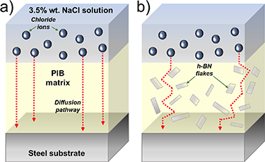
Figure 6. Schematic diagrams of diffusion pathways followed by chloride ions through (a) pristine PIB and (b) h-BN/PIB composite coatings from the NaCl aqueous solution to the surface of the steel substrate.
Download figure:
Standard image High-resolution imageTable 3. Performance comparison of h-BN/PIB 5% coating with literature in terms of corrosion rate.
| Filler | Matrix | Filler content (wt.%) | Thickness (μm) | CR (mm yr−1) | References |
|---|---|---|---|---|---|
| h-BN | PIB | 5 | 58 ± 7 | 7.4 × 10⁻⁶ | This work |
| f-BNNS-PPy | Epoxy | 0.5–3 | 40 | 1.5 × 10⁻⁵ | [85] |
| B-doped graphene | PU | 0.5 | 25 ± 2 | 1.6 × 10⁻⁵ | [86] |
| PPyNG | Epoxy | 2 | 20 | 8.9 × 10⁻⁵ | [87] |
| BNNDs@GNSs | Epoxy | 0.1 | 20 | 6.3 × 10⁻⁵ | [88] |
| Fh-BN, SZP | Epoxy | 0.5, 0.5 | 30 ± 2 | 2.3 × 10⁻⁴ | [89] |
| GNSs | PMMA | 0.5 | 10 ± 1 | 8.6 × 10⁻³ | [90] |
a Functionalized boron nitride nanosheets-polypyrrole. b Polypyrrole nanowires-graphene. c Boron nitride nanodots embedded at graphene nanosheets. d Functionalized hexagonal boron nitride, strontium zinc phosphate.
More in detail, although graphene was initially proposed as an anticorrosive coating due to its impermeability and chemical stability, the presence of pinholes or scratches in practical situations leads to accelerated local corrosion due to galvanic processes taking place at the junction between the graphene and the metal. In this particular case, graphene behaves as the cathode whereas the steel acts as the anode, being the latter preferentially attacked upon exposure to the corrosive media [32]. In contrast, h-BN flakes behave as a physical barrier while acting as electronic and ionic insulators due to their ionic-free structure and absence of conjugation, resulting in an ideal functional filler for anticorrosion polymeric coatings, even in absence of traditional sacrificial inorganic fillers (e.g. Zn and Mg) [39].
3.4. Long-term immersion test
To investigate the behaviour of the protective coatings during long-term operation, structural steel coated with h-BN/PIB 5% composite and pristine PIB were immersed in 3.5 wt% NaCl aqueous solution over 1000 h while monitoring their Ecorr values following the protocol described in the ASTM G31-72 standard. As shown in figure 7, the Ecorr at the beginning of the immersion test was around 0.09 V versus Ag/AgCl and 0.03 V versus Ag/AgCl for structural steels coated with h-BN/PIB 5% and pristine PIB, respectively. Despite the presence of Ecorr fluctuations, both systems remained stable over time. After the 1000 h immersion test, the measured Ecorr values were approximately 0.08 V for structural steels coated with h-BN/PIB 5% composite and 0.04 V for pristine PIB.
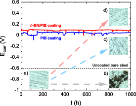
Figure 7. Ecorr over 1000 h of immersion in 3.5 wt.% NaCl aqueous solution of structural steel substrates coated with pristine PIB and h-BN/PIB 5%. The insets show optical microscopy images of bare steel substrate (a) before and (b) after 1000 h of immersion in 3.5 wt.% NaCl aqueous solution and steel substrate coated with (c) pristine PIB and (d) h-BN/PIB 5% composite coatings after 1000 h of immersion in the same saline solution.
Download figure:
Standard image High-resolution imageTo further assess the effect of the immersion on the structural integrity of the steel substrate, optical microscopy images were taken on the samples after delaminating the coatings (insets, figure 7). After 1000 h of immersion in 3.5 wt.% NaCl aqueous solution, the surface of the structural steel substrate was extremely corroded (figure 7(b)) compared to the same sample before the immersion (figure 7(a)). On the contrary, pristine PIB coating provides clear protection against structural steel substrate oxidation (figure 7(c)). Nevertheless, there are still areas that show the corrosion of the metallic substrate. In contrast, the substrate coated with h-BN/PIB 5% reveals a surface free of oxidation products (figure 7(d)), which is similar to the surface of the bare substrate before the immersion test. This observation further confirms that the composite coating optimally protects the underlying structural steel against corrosion, whereas the inferior anticorrosion performance of PIB coating may still allow some amount of corrosive species to reach the surface of the substrate.
The evolution of the anticorrosive properties of both systems during the immersion test was evaluated by EIS measurements. Figure 8 presents the Bode plots of pristine PIB and h-BN/PIB 5% coated structural steel measured over 26 d of immersion. Figures 8(a) and (c) shows that the bare steel substrate exhibits the lowest |Z|0.1 Hz value of ∼103 Ω cm2. The initial |Z|0.1 Hz values measured for the pristine PIB- and h-BN/PIB 5%-coated structural steel, obtained after a preconditioning time of 2.5 h, were 5.6 × 10⁵ Ω cm2 and 3.5 × 10⁶ Ω cm2, respectively, reflecting the superior anticorrosion performance of the composite coating. During the first ten days, the evolution of the Bode plots indicates the occurrence of some change related to the anticorrosion coatings. The changes in the Bode plots for anticorrosion systems during the first days of immersion have been often observed in literature for anticorrosion coatings [13, 83, 95, 96]. However, such changes are not necessarily associated with a loss of the protective efficiency of the coating if high |Z|0.1 Hz are still shown. The failure of an anticorrosion coating is instead evidenced by a drastic change of the Ecorr of the system towards the Ecorr exhibited by the bare substrate (e.g. −0.604 V versus Ag/AgCl in bare steel).
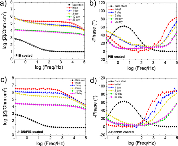
Figure 8. Bode plots of (a), (b) pristine PIB- and (c), (d) h-BN/PIB 5%-coated structural steel substrates.
Download figure:
Standard image High-resolution image
In addition, the failure of the coating is typically associated with a continuous change of |Z|0.1 Hz over the subsequent days until approaching the values expressed by the unprotected substrate under corrosion. In this work, the monitored Ecorr of the PIB-based coatings remained nearly constant over 1000 h of continuous immersion. After two days of immersion, h-BN/PIB 5%-coated structural steel has still shown a |Z|0.1 Hz as high as 6.2 × 10⁵ Ω cm2, which is superior to the values exhibited by the PIB-coated structural steel. After ten days of immersion, the systems based on pristine PIB and composite coatings showed |Z|0.1 Hz values of 1.7 × 10⁴ Ω cm2 and 2.9 × 10⁴ Ω cm2, respectively. After more than ten days, both systems did not experience any |Z|0.1 Hz change, indicating optimal anticorrosion performance over time.
4. Conclusions
In summary, we presented a method for the fabrication of composites consisting of industrially produced few-layer hexagonal boron nitride (h-BN) flakes embedded into PIB. The as-prepared composite is used as a protective anticorrosion coating for steel substrates immersed in aqueous saline solution. The surface roughness of the as-produced composites increases with the h-BN content, whereas the hydrophobicity reaches the maximum value at an h-BN content of 10 wt.%. A further increase of the h-BN contents resulted in a decrease of the hydrophobicity due to the aggregation of the nanofillers. The anti-corrosion performance of the composites is evaluated at various h-BN contents, correlating the results with the physicochemical properties of the coatings. In 3.5 wt.% NaCl water, the structural steel coated by the h-BN/PIB composite with an h-BN content of 5 wt.% exhibited the minimum corrosion rate of 7.4 × 10⁻⁶ mm yr−1, which is almost two orders of magnitude lower than the one measured for pristine PIB-coated structural system. The hydrophobic h-BN flakes embedded into PIB hinder the diffusion of the electrolyte ions passing through the protective system, thus providing further protection to the steel substrate compared to the pristine polymer. The stability of the composite coating was evaluated by monitoring the corrosion potential over 1000 h of immersion in 3.5 wt.% NaCl water. Together with EIS data and optical microscopy imaging, these results demonstrate the long-term stability of the composite anticorrosion coating. Our results reveal that h-BN flakes can act as ideal additives for anticorrosion coatings in marine environments.
Data availability statement
All data that support the findings of this study are included within the article (and any supplementary files).
Funding
This project has received funding from the European Union's Horizon 2020 research and innovation programme under Grant Agreement No. 881603—GrapheneCore3.
B Martin Garcia thanks Gipuzkoa Council (Spain) for the frame of the Gipuzkoa Fellows Program.
Author's contribution statement
M A Molina-Garcia: Conceptualisation, Methodology, Formal analysis, Data curation, Validation, Writing-original draft, Writing-review & editing, Visualisation, Supervision. S Bellani: Conceptualisation, Methodology, Writing-review & editing. I Conticello: Data curation, Validation. A E del Rio Castillo: Conceptualisation, Resources, Data curation, Validation, Writing-review & editing. L Gabatel: Methodology, Formal analysis. M I Zappia: Methodology, Formal analysis. M Eredia: Methodology. S Thorat: Data curation, Validation. B Martin Garcia: Data curation, Validation. L Ceseracciu: Data curation, Validation. M Piccinni: Data curation, Validation. F Bonaccorso: Conceptualisation, Resources, Funding acquisition, Supervision, Writing-review & editing, Visualisation.
Conflict of interest
F B is the co-founder, Chief Scientific Officer and Board Member, S B, A E D C, and S T are Senior Scientists, and M A M G, I C, L G, M I Z, and M E are Scientists at BeDimensional S.p.A., a company that is commercializing 2D materials.
Supplementary data (0.6 MB DOCX)