
Abstract
The objective of this study was to investigate new 3D printable materials, namely PORO-LAY series in both solid and flexible forms, on behalf of their radiological properties by measuring their Hounsfield units (HUs) values at varying infill densities, different infill structures and several kinds of fluids in order to assess their suitability as tissue mimicking materials (TMMs) for phantom applications. In this study, it was found that PORO-LAY materials can be used to achieve low and high values of HU ranges from −990 to +950 depending on their infill density and the filling fluids. In addition, PORO-LAY materials have an acceptable dimensional stability and dimensional accuracy in their solid and flexible forms. The results also indicate that the shape of infill pattern influences the values of HU with percentage difference ranges from 3 to 33% depending on the selected infill structure. The results of this study showed that PORO-LAY materials were feasible to be used as TMMs for CT and PET/CT applications.
Export citation and abstract BibTeX RIS

Original content from this work may be used under the terms of the Creative Commons Attribution 4.0 licence. Any further distribution of this work must maintain attribution to the author(s) and the title of the work, journal citation and DOI.
1. Introduction
Additive manufacturing (AM) is progressively utilized to refer to many different effective, low-cost technologies that are used to produce complex shapes of physical models from three-dimensional (3D) computer aided design (CAD) data [1]. The most common technology of AM technologies is three-dimensional (3D) printing.
In the medical imaging, 3D printing is now being explored for the creation of phantom models from flexible 3D-printable tissue mimicking materials (TMMs). Regarding TMMs to be used for medical imaging phantoms, the physical, chemical and imaging characteristics should be as close as possible to human tissue. This concerns in particular material properties that should match to tissues of human body for each type of imaging modality [2, 3]. They include equivalent Hounsfield unit values, good dimensional accuracy and capability to absorb ionic solutions or contrast agents with defined HU value for computed tomography (CT) phantoms [2] as well as for animal and human hybrid imaging modalities, e.g. the combined positron emission tomography and computed tomography PET/CT. The radiological properties of any material or tissue can be represented by the Hounsfield unit value (HU) [4] where the attenuation suffered by the object is transformed into a grey scale of Hounsfield values that determines the nature of the tissue [5].
Systematic review about 3D printable materials as TMMs and their applications for phantom constructions for different imaging modalities addressed some limitations about the available commercial rigid 3D printable materials and the traditional manufactured phantoms using molding techniques [6]. For example, only a small number of 3D printable materials have been investigated regarding to their radiological properties and there is a lack in 3D printable materials which could be used as TMMs, the CT numbers of the most rigid 3D printable materials, e.g. Acrylonitrile butadiene styrene (ABS) and Polylactic acid (PLA) do not approach high values of the HU to mimic the bone and other dense parts of the human body, which is the disadvantage of most 3D printable materials [7]. Moreover, various kinds of non-printable materials were examined for the purpose to be used as TMMs for phantoms constructions, e.g. gypsum, silicone and agarose gel. However, these materials are only used to develop phantoms using traditional molding techniques and the evaluation of imaging systems is often restricted with their use, the complex geometry as well as the realistic structures of the human body cannot be replicated [8].
PORO-LAY materials are new low cost 3D printable filaments consisting of a thermoplastic polyurethane (TPU) copolymer with a dissolvable polyvinyl alcohol (PVA) component [8]. PORO-LAY materials have been shown to be useful for modeling elastic tissues [9] , developing ultrasound (US) phantom [7], multi-material printing of realistic white and grey matter structures for magnetic resonance imaging (MRI) and positron emission tomography (PET) applications [8, 10]. In addition, LAY-FOMM, which is the most common materials of PORO-LAY series, is a promising material for FDA approved drug delivery applications [11]. To our knowledge, no study in the literature has examined the radiological properties and the dimensional accuracy and stability of solid and flexible form of 3D printable PORO-LAY materials for CT and PET/CT applications.
In this study, our aim is to reveal the radiological properties and dimensional stability of four different types of PORO-LAY filaments namely LAYFOMM 40, LAYFOMM 60, LAY-FELT and GEL-LAY by measuring their Hounsfield unit values and their dimensional errors when they are solid and after dissolving the PVA component. The HU values were evaluated by varying the infill density, the infill structure in their solid form and by employing different kinds of fluids to modify their radiological properties in their flexible form.
2. Material and methods
2.1. Phantom materials
Four different types of low cost experimental PORO-LAY filaments (LAYFOMM 40, LAYFOMM 60, GEL-LAY and LAY-FELT) were used in this study, all purchased from its inventor (Kai Parthy, CC-products, Cologne, Germany). All PORO-LAY materials are tough and shatter resistant in its basic form, and can be printed into any required shape with any commercially available fused deposition modeling 3D FDM printer. After printing, the printed objects can be placed in a water bath for three days to dissolve the PVA component and the porous structure of TPU network remains. The density, Young's Modulus as well as the nozzle temperature required for printing all PORO-LAY series are summarized in table 1.
2.2. 3D printing
Testing samples with different infill densities, infill patterns as well as realistic bone structure were printed using a KISS-200 extended 3D-FDM printer with dual extruders (ReprapUniverse, Kerkrade, Netherlands). The specifications of this printer are shown in table 2.
Table 2. Specifications for 3-D printer KISS 200.
| Specifications | Specification value |
|---|---|
| Build Volume (mm × mm × mm ) | 200 × 200 × 340 |
| Printing speed ( mm s−1) | 10–80 |
| The layer height resolution (mm) | 0.05–0.3 |
| Maximum printing temperature (°C) | 270 |
| Materials diameter (mm) | 1.75 |
| Nozzle diameter (mm) | 0.5 |
| Supported input file types | *.stl,*.obj,*.amf,*.xml,*.3mf |
The construction of the samples included four different steps: (I) computer–aided design (CAD); (II) export of the stereolithography (STL) file; (III) digital slicing into multiple two dimensional (2D) layers; (IV) export for printing as a G-code file. Step I and II were accomplished using 'Free CAD', which is an open source software. Slic3r (Version 1.3.0) was used to perform steps III and IV. This software is also available as an open-source software.
For the first part, using the solid form of PORO-LAY materials, 20 samples were printed in a rectangular shape with dimensions of 20 × 20 × 4 mm, made from LAYFOMM 40, LAYFOMM 60, GEL-LAY and LAY-FELT with various infill densities of 10%, 30%, 50%, 70% and 100% for the purpose of evaluating the HU values versus the infill density. LAYFOMM 40 was used to print 9 different infill patterns, as shown in figure1, with infill density of 50% in a rectangular shape with dimensions of 20 × 20 × 4 mm to examine the influence of infill structure on the acquired HU value.

Figure 1. Nine different infill patterns created by Slic3r software.
Download figure:
Standard image High-resolution imageWhile in the second part, using PORO-LAY materials in their flexible form after dissolving the PVA component, 16 samples of cubic shapes were printed using LAYFOMM 40, LAYFOMM 60 and LAY-FELT materials with dimensions of 20 × 20 × 20 mm with infill density of 100%, to evaluate the influence of different fluids on their HU values. Regarding to the dimensional accuracy measurement, cubic, shaped samples with dimensions of 20 × 20 × 20 mm were printed and the variation in length, width and height axis were measured when they are solid and after dissolving the PVA component. All samples were printed and then placed in a water bath for three days to dissolve the PVA component, then the samples were removed from the water bath and placed in an ultrasonic bath using lower frequency range (15–25 kHz)—to prevent damaging the samples if higher frequencies were used [12] - for 10 min to remove air bubbles inside the printed samples [13]. After that, the samples were placed on a dry surface for one minute to get rid of the excess water and these wet samples were scanned using CT. Regarding to the printed samples in the second part, the wet samples were dried—after dissolving the PVA component—and placed in an oven at temperature of 100 °C–120 °C for 10 min, then placed inside containers filled with different kinds of fluids for 10 min, and then the same samples were removed and placed in a dry surface for one minute to remove the excessive fluids and scanned again using CT. Different kinds of fluids were used in this study, namely distilled water, vegetable oil containing 70% saturated fats, and saturated sodium chloride solution (NaCl).
2.3. Segmentation
A CT image of proximal epiphysis end of a long bone (humerus) was obtained in Digital Imaging and Communications in Medicine (DICOM) format. Thereafter, the DICOM CT dataset was loaded into 3D Slicer software, (National Alliance for Medical Image Computing NA-MIC), version (4.10.2), to segment the bone structure and ensure that all surrounding structures were completely removed. For more reliable segmentation, each slice was segmented in different orientation using a threshold function, which was adjusted manually. This approach was used to segment the DICOM dataset so, that only the proximal epiphysis end of a long bone (humerus) structure with dimensions of 43 × 44 × 50 mm were kept in the final segmented model. Subsequently, for the aim of further image post-processing and 3D printing, the segmented structures were saved in a standard tessellation language (STL), figure 2 shows a 3D image of the final STL file. The same procedures were followed to print realistic shapes of proximal epiphysis humerus bone using LAYFOMM 60. Thereafter, the printed objects were placed in a water bath for 3 days, dried and placed in a NaCl solution for 10 min and scanned within Siemens Inveon multimodality SPECT-CT imaging scanner.

Figure 2. Three dimensional image of the STL printable file of the segmented DICOM dataset of proximal epiphysis humerus bone.
Download figure:
Standard image High-resolution image2.4. Computed tomography imaging
In order to measure the HU values of the printed samples, the CT component of a Siemens Inveon multimodality SPECT-CT imaging scanner (Siemens Preclinical Solutions; Knoxville, TN) was used to acquire images for all printed samples of PORO-LAY materials. CT scans were acquired with the samples in solid and flexible form under the same scanning condition using X-ray tube voltages of 80 kV, X-ray tube current of 492 μA, spot size of 50 mm and filters of thickness 1.5 mm.
2.5. Data analysis and hounsfield unit measurement
In CT scan, Hounsfield Unit (HU) reflects the degree of X-ray attenuation by the scanned object. HU is a value constituting the grayscale level of a CT image, and it can be calculated by the defined equation below [4]:

Where μmaterial is the linear attenuation coefficient of the material and μwater is the linear attenuation coefficient for water. Air has HU value of −1, 000, because its μ value is zero, and water has HU value of zero [4].
The data analysis for the acquired images was performed by using PMOD software (PMOD Technologies, Zürich, Switzerland). A 150 × 150 pixel (238.5 mm2) region of interest (ROI), centered axially, was analyzed with respect to mean HU and its standard deviation for all printed samples in their solid and flexible forms.
3. Results and disscusion
In this study, solid samples of LAYFOMM 40, LAYFOMM 60, GEL-LAY and LAY-FELT, printed using a rectilinear infill pattern at infill densities of 10%, 30%, 50%, 70% and 100%, were scanned using a Siemens Inveon multimodality SPECT-CT imaging scanner. Figure 3 includes a graph showing HU values depending on the infill density for all PORO-LAY materials when they are solid.
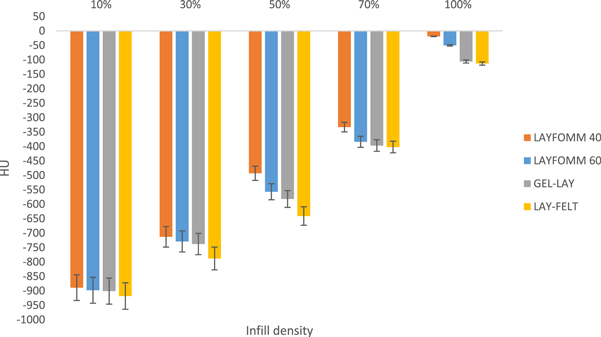
Figure 3. HU values versus the infill densities of different types of PORO-LAY materials in solid state.
Download figure:
Standard image High-resolution imageFrom figure 3, at 100% infill density, LAYFOMM 40 has the highest HU value (−19 ± 10) among PORO-LAY series, followed by LAYFOMM 60 (−50 ± 14), GEL-LAY (−106 ± 23) and LAY-FELT (−113 ± 27). The variations in their HU values are due to the value of the mean density for each material which was summarized in table 1. In addition, the HU values at 10% infill density for LAYFOMM 40, LAYFOMM 60, GEL-LAY and LAY-FELT were −889, −898, −901 and −919, respectively. While the HU values for LAYFOMM 40, LAYFOMM 60, GEL-LAY and LAY-FELT were −19, −50, −106 and −113, respectively, at an infill density of 100%. Therefore, the HU values of solid printed PORO-LAY materials are directly dependent on the infill density of the printed structures. These results are consistent with the previous findings about rigid printable materials [14]. These results also indicate that the densities of the scanned object are directly linked to the radiation attenuation. Denser material with greater attenuation of X-ray beams has positive values of HU and appears bright, less dense material with less attenuation of X-ray beams has negative values of HU and appears dark [5, 15].
To calculate the appropriate infill density required to simulate the desired negative HU values using solid form of PORO-LAY series. Equation (2) can be used, and the parameters for the fitted relationship between the infill density and the HU value in their rigid form are shown in table 3.

Table 3. Values of fitting parameters and R-squared values of all PORO-LAY materials in solid state.
| Parameters | ||||
|---|---|---|---|---|
| Material | a | b | c | R-squared value |
| LAYFOMM-40 | 0.0019 | 9.97 | −999.4 | 0.9924 |
| LAYFOMM-60 | 0.0024 | 6.22 | −970.4 | 0.9933 |
| GEL-LAY | 0.0020 | 7.09 | −981.6 | 0.9966 |
| LAY-FELT | 0.0029 | 2.39 | −966.0 | 0.9993 |
In the case of LAYFOMM 40, LAYFOMM 60, GEL-LAY and LAY-FELT, the R2 value was greater than 0.99 for all PORO-LAY materials. Indicating that the fitting was also successful like other rigid, 3D printable materials [14].
This study also investigates the effects of the shape of the used infill patterns on the HU values for rigid form of PORO-LAY materials. Figure 4 demonstrates that the direction of the print or the shape of the void in the printed samples has significant effects on the measured HU values of PORO-LAY materials.
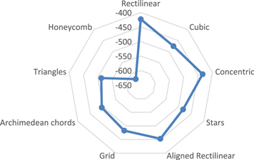
Figure 4. The HU values of 9 infill patterns of 50% infill density made of LAYFOMM 40.
Download figure:
Standard image High-resolution imageFigure 4 indicates that the shape of the pattern will influence the interaction between X-ray photons with the printed material depending on the relative electron density of each infill structure. Table 4 summarizes the values of the relative electron density for 9 infill patterns.
Table 4. The relative electron density and the measured HU value of 9 infill structures using solid form of the printed LAYFOMM 40 at 50% infill density.
| Infill patterns | Relative electron density | Measured HU value | |
|---|---|---|---|
| 1 | Rectilinear | 0.577 ± 0.02 | −423 ± 21 |
| 2 | Cubic | 0.525 ± 0.03 | −475 ± 34 |
| 3 | Stars | 0.518 ± 0.03 | −482 ± 31 |
| 4 | Aligned Rectilinear | 0.547 ± 0.03 | −453 ± 29 |
| 5 | Grid | 0.517 ± 0.03 | −483 ± 33 |
| 6 | Archimedean chords | 0.505 ± 0.03 | −495 ± 30 |
| 7 | Triangles | 0.488 ± 0.04 | −512 ± 35 |
| 8 | Honeycomb | 0.377 ± 0.04 | −623 ± 37 |
| 9 | Concentric | 0.566 ± 0.03 | −434 ± 30 |
Figure 4 and table 4 showed that the rectilinear infill structure would produce a higher HU value, while honeycomb infill structure will produce a lower HU value for each material at each infill density, with a percentage difference of 33%. This is due to the relative electron density of each infill pattern. Regarding to the honeycomb structure, which is a structure commonly used to be lightweight, less dense with good mechanical properties compared to other infill patterns, has lower relative electron density of 0.377 ± 0.04. While the rectilinear infill pattern, which is a pattern that used to be denser with poor mechanical properties compared to the honeycomb structure, has higher relative electron density of 0.577 ± 0.02. Therefore, the shape of the void has significant effects, ranges from 3%–33%, on the measured HU of the solid form of PORO-LAY materials.
Geometrical accuracy is also an important feature essential for TMMs to be used in phantoms applications and can be assisted using a digital Vernier caliper gauge, to measure the variation in length, width and height axis of the printed samples and compared them with the original STL model [16]. In this study, cubic, printed shapes of LAYFOMM 40, LAYFOMM 60, GEL-LAY and LAY-FELT materials were printed using 100% infill density of dimensions of 20 × 20 × 20 mm. Figure 5 shows the quality of deposition of all printed samples when they are solid and flexible and figure 6 shows the dimensional variation in length, width and height axis for all PORO-LAY materials when they are solid and flexible.
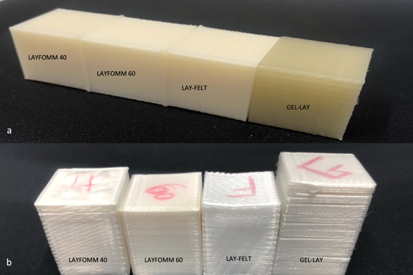
Figure 5. The quality of deposition of all PORO-LAY materials when they are (a) solid and (b) flexible.
Download figure:
Standard image High-resolution image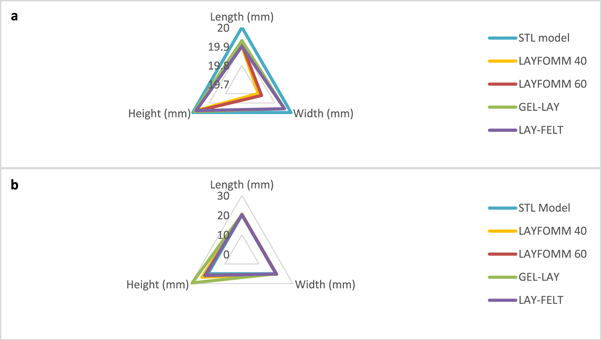
Figure 6. The dimensional variations in length, width and height axis between the (a) solid and (b) flexible form of printed objects of PORO-LAY materials and the original STL model.
Download figure:
Standard image High-resolution imageRegarding to the solid form of PORO-LAY materials, GEL-LAY showed the highest dimensional accuracy among PORO-LAY materials, followed by LAY-FELT, LAYFOMM 60 and LAYFOMM 40. While in the flexible form, LAYFOMM 60 showed the highest dimensional stability with the least shape error, followed by LAYFOMM 40, LAY-FELT and GEL-LAY. The variations in length, width and height axis are due to the heat shrinkage after cooling down the printed objects to reach the room temperature for the solid forms, and due to the volume expansion caused by fluid diffusion for the flexible forms. Table 5 summarizes the percentage error of the final shape for all PORO-LAY materials in the length, width and height axis for both forms. These variations could be minimized by utilizing the rescaling options which are provided by 3D printing techniques and not available in the traditional molding techniques.
Table 5. Values of % error in the length, width and height axis for all PORO-LAY materials in solid and flexible forms.
| % Error in length axis | % Error in width axis | % Error in height axis | ||||
|---|---|---|---|---|---|---|
| Material | Solid | Flexible | Solid | Flexible | Solid | Flexible |
| LAYFOMM 40 | 0.10% | 2.00% | 0.90% | 2.10% | 0.15% | 17.85% |
| LAYFOMM 60 | 0.05% | 1.85% | 0.80% | 2.25% | 0.10% | 7.30% |
| GEL-LAY | 0.15% | 0.95% | 0.40% | 0.10% | 0.05% | 46.90% |
| LAY-FELT | 0.20% | 0.25% | 0.50% | 1.05% | 0.10% | 9.45% |
A tunable radiological property is also another interesting feature that should be available for 3D printable materials to be used as TMMs for a wide range of practical medical applications. This study investigated the modified values of HU of LAYFOMM 40, LAYFOMM 60 and LAY-FELT, which showed the highest dimensional stability in the flexible form after washing away the PVA component, after filling the created pores with different types of fluids such as distilled water, vegetable oil and ionic solutions to tune their radiological properties. Figure 7 shows the HU values of 100% infill density of the flexible form of LAYFOMM 40, LAYFOMM 60, LAY-FELT.
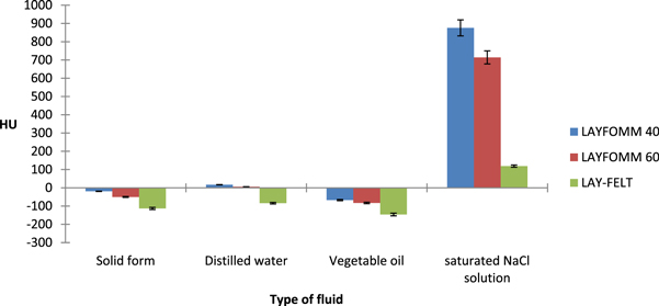
Figure 7. Hounsfield unit values of LAYFOMM 40, LAYFOMM 60 and LAY-FELT at infill density of 100% using different kinds of fluids.
Download figure:
Standard image High-resolution imageFigure 7 indicates that the Hounsfield unit values of the flexible form of LAYFOMM 40, LAYFOMM 60 and LAY-FELT can be modified depending on the type of the fluid used. For example, filling the created pores of LAYFOMM 40, LAYFOMM 60 and LAY-FELT with distilled water will modify the HU values from −19, −50 and −133 to 17, 6 and −84 respectively. The new values of watery flexible form of PORO-LAY materials are within the accepted range of CT number of skin tissue for childs and adults [17]. In addition, using vegetable oil to fill the pores will modify the HU value of LAYFOMM 40 from −19 to −67, thus the new value of HU for the oily flexible form of LAYFOMM 40 are within the accepted range of the CT number of fat tissues for childs and adults [17]. Moreover, using NaCl solution to fill the porous structure of LAYFOMM 40, LAYFOMM 60 and LAY-FELT will modify the HU values from −19, −50 and −133 to 876, 714 and 119, respectively. Therefore, the new values of HU for ionic flexible PORO-LAY materials, after filling the pores with NaCl, are within the accepted range of CT number for bone [17]. For more accurate comparison between the HU values of PORO-LAY materials and the HU values of soft tissues and organs of the human body, further study should be conducted using higher X-ray tube voltages, more than 80 kV, to see the effects between the applied kV and the HU values of the solid and flexible forms PORO-LAY materials.
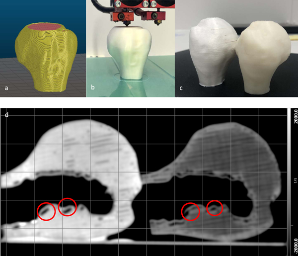
Furthermore, to mimic the HU values as well as the shape of the bone, a realistic bone structure with dimensions 43 × 44 × 50 mm was printed using LAYFOMM 60, which showed the highest dimensional stability among PORO-LAY materials in their flexible form, and the necessary rescaling in all axis have been applied using Slic3r software based on the values summarized in table 5.
Figure 8. Presents a schematic flowchart of the process of slicing, printing and subsequent acquiring CT image of the 3D realistic bone shape before and after tuning their HU values using NaCl solution.
Figure 8. (a) 3D image of the sliced STL file which was created from the segmented DICOM dataset of the bone structure (b) The quality of deposition during the printing process of the created STL model (c) the final printed shape in solid (right) and flexible form (left) using 100% infill density of LAYFOMM 60 and (d) the acquired CT image of the solid (right) and flexible (left) form of the printed shape.
Download figure:
Standard image High-resolution image
As shown in figure 8, the flexible form of LAYFOMM 60 is brighter than the solid form due to the altered relative electron density, after immersion the flexible printed shape in the NaCl solution, and hence a new HU value which equals to 950 ± 75 was approached. Further improvements on the printing settings e.g. dimeter of the printing nozzles, number of perimeters and filling angle will lead to achieve an excellent homogeneity and resolution without any gabs, indicated as red circles in figure 8, between the printed materials and perimeters or the walls of the object. Therefore, LAYFOMM 60 in particular and PORO-LAY materials in general, are feasible to be used in their flexible forms to reach high values of HU to mimic the shape and the CT number of the realistic human bone or any desired organ and tissue.
4. Conclusion
The present study evaluated the radiological properties of PORO-LAY materials in their solid and flexible forms. The results of this study indicate that PORO-LAY materials have many unique properties including:
- PORO-LAY materials, in their solid form, like other rigid 3D printable materials, at which the infill density and the infill structure have significant effects on their HU values.
- PORO-LAY materials have the ability to soak different types of fluids, e.g. water, oil, contrast agents as well as radioactive tracers, therefore, their HU can be modified and tuned by changing the type of fluid only.
- These materials also provide an acceptable dimensional stability and accuracy in their solid and flexible forms. Besides, using 3D printing techniques with PORO-LAY materials provide many options to reproduce the exact shape and dimensions, by applying the necessary rescaling in x, y and z direction.
- The solid and flexible forms of PORO-LAY materials could provide a wide range of HU values depending on the selected infill density, patterns and fluids. Thus, they might be used as TMMs for computed tomography (CT), positron emission tomography (PET), single-photon emission computed tomography (SPECT) as well as PET/CT applications.
- PORO-LAY materials are available as 3D printable filaments and can be printed using any commercial 3D FDM printer without any visible change in the shape and dimensions (warping deformation) of the printed objects.
- The organs and tissues that have negative HU values, e.g. tumor, fats and soft tissues, might be simulated using solid printed objects of PORO-LAY materials. In addition, using LAYFOMM 40, LAYFOMM 60 and LAY-FELT in their flexible, porous forms are feasible to be used to approach high HU values for bones, and their HU can also be altered to mimic any desired CT number to simulate different types of human tissues and organs. In general, PORO-LAY is a low cost, commercially available TMMs and these materials might be employed by researchers and scientists in many applications in the medical field research.
Acknowledgments
The DICOM image datasets used in this experiment were from the Laboratory of Human Anatomy and Embryology, University of Brussels (ULB), Belgium. The authors acknowledge financial support by the Federal Ministry of Education and Research of Germany in the framework of the Palestinian-German Science Bridge (BMBF grant number 01DH16027).