

Abstract
In this study, a new series of 3D printable rubber-elastomeric polymer called PORO-LAY materials have been investigated regarding their suitability to serve as tissue mimicking materials (TMMs) for MRI phantoms. PORO-LAY materials have been previously used in biofuel cell developments, particle filtrations and modeling elastic tissues. We evaluated the electrical permittivity, electrical conductivity, spin-lattice T1-relaxation time and acquired the MRI contrast for simple and multi-material complex 3D printed shapes made of PORO-LAY materials at 3.0 T. The results showed a T1 diversity within PORO-LAY materials, which reveals in different MR image contrasts. The outcome favors PORO-LAY as an appropriate candidate that can be used in multi-materials additive manufacturing to produce realistic shapes such as white/grey matter structures for MRI phantoms with visible clear contrast. Finally, this study could serve as a reference and guideline when using these materials as tissue mimicking materials for different types of human body tissues and provide a promising opportunity to design novel phantoms for a wide range of MRI applications.
Export citation and abstract BibTeX RIS

Original content from this work may be used under the terms of the Creative Commons Attribution 4.0 licence. Any further distribution of this work must maintain attribution to the author(s) and the title of the work, journal citation and DOI.
1. Introduction
Medical imaging phantoms are designed for machine calibration, imaging optimization, benchmarking, comparison of multimodal system performances and developments of novel imaging techniques [1]. Commercial phantoms are usually machine‐made [2] however, in recent time, the cost of three‐dimensional (3D) printing has dramatically decreased while the use in medical imaging field evolved [3–5, 2, 6]. The combination of 3D printing technology and tissue‐mimicking materials (TMMs) has enabled anatomically precise phantom constructions with bioequivalent medical imaging characteristics.
Regarding TMMs to be used for medical imaging phantoms, the physical, chemical and imaging characteristics should be as close as possible to human tissue. This concerns in particular material properties that should match to tissues of human body for each type of imaging modality [7]. It includes equivalent Hounsfield unit values for computed tomography (CT) phantoms [8], relaxation times for magnetic resonance imaging (MRI) phantoms [9] as well as material densities and mechanical vibrations for Ultrasound (US) phantoms [7, 10, 11]. Furthermore, equivalent characteristics within the radiotracer uptake, radiotracer distribution and reproducibility for positron emission tomography (PET) phantoms [7] are required too.
In many previous studies various kinds of 3D-printable materials were discussed for the purpose to be used as TMMs for phantoms constructions. Hereby, e.g. high impact polystyrene [12], Acrylonitrile butadiene styrene (ABS), Polyactide (PLA) and Photoluminescent PLA with different combinations [13] were used to construct CT phantoms. Furthermore, ABS coated with epoxy resin and Fullcure 720 polymer were used for MRI [14], US [15], SPECT [16], and PET/CT [17] phantoms.
Most of these materials are inherently relatively stiff materials and as a consequence, their application is limited. Thus, materials such as TPU that offers a greater flexibility and are tailored to applications at hand, are more preferred for phantoms applications. However, there were no studies that investigate the properties of new experimental low cost 3D printable materials such as thermoplastic polyurethane (TPU) copolymer called PORO-LAY series [18]. The main here will be the use of these materials it as TMMs for phantoms construction regarding different types of imaging modalities, especially for MRI applications.
PORO-LAY filaments consist of thermoplastic polyurethane (TPU) copolymer with polyvinyl alcohol (PVA) components [19]. This material has different types, namely LAYFOMM 40, LAYFOMM 60, LAY-FELT and GEL-LAY. All these types contain different concentrations of PVA components. They can be dissolved in a water bath, leaving a Nano-porous and sponge like TPU network which has been shown to be useful for biofuel cell development [20], particle filtration [19] and modeling elastic tissues [21].
Compared to other commercial 3D-printable materials, PORO-LAY materials provide many unique properties. Due to their predilection for blocking printing channels, soft and sponge materials are difficult to print in complex shapes and hence rarely used as TMMs. But PORO-LAY materials, available in 1.75 mm filaments, can be printed in any complex shape such as in rigid forms that can be converted into flexible and sponge forms within the same object. The created porosity inside these materials makes PORO-LAY not only to be a good candidate by using radiotracers in positron emission tomography PET [22], but provides also different gray scales within magnetic resonance imaging representing different brain tissues. Moreover, since it is a low cost commercially available material, it can be employed by researchers and scientists in many applications. Herbey, most prominent to be mentioned is the application of PET/MRI phantoms in the medical reserach field [22].
This study aims to explore some physical and medical imaging properties of various types of PORO-Lay materials which are relevant to be considered by TMMs in MRI phantoms. It specifically includes the investigation of T1-relaxation time and dielectric properties of four different types of PORO-LAY. Furthermore, the relationship between the MRI associated tissue mimicking materials and their T1-relaxation time as well as the dielectric properties of these materials are also discussed in this study.
2. Materials and methods
2.1. PORO-LAY filaments
Different types of low cost experimental PORO-LAY filaments (LAYFOMM 40, LAYFOMM 60, GEL-LAY and LAY-FELT) were used in this study, all purchased from its inventor Kai Parthy (CC-products, Cologne, Germany). The material consists of a thermoplastic polyurethane (TPU) copolymer with polyvinyl alcohol (PVA) [19]. All PORO-LAY materials are tough and shatter-resistant in their basic form, and can be printed into any required shape with any commercially available 3D-FDM printer. After printing, the PVA component can be dissolved in a water bath leaving a Nano-porous and sponge-like TPU network.
2.2. 3D printer
Four different types of PORO-LAY filaments, namely LAYFOMM 40, LAYFOMM 60, LAY-FELT and GEL-LAY have been used in spin-lattice T1-relaxation time measurement. All were printed with a KISS 200 Extended 3D-FDM printer with dual extruders (ReprapUniverse, Kerkrade, Netherlands) in cubic shapes of dimension 20 × 20 × 20 mm - for simplicity purposes - and an infill density of 100%. The specifications of this printer are shown in table 1. The construction of the printed specimens included four different steps: (I) computer–aided design (CAD); (II) export of the STL files; (III) digital slicing into multiple 2D layers; (IV) export for printing as a G-code file. Steps I and II were accomplished using 'Free CAD', an open source software [23]. Slic3r (version 1.3.0), a free available software too, was used to perform steps III and IV [24]. After performing step IV, the printed samples were placed for three days in water bath at room temperature to dissolve the PVA component. Hereby, an ultrasonic bath and warm water might be used to speed up the dissolving of the PVA component. Subsequently the samples were removed from the water bath and dried for five minutes by using soft, absorbent and disposable papers. Thereafter, they were placed again in a 50 ml falcon tube filled with distilled water and scanned within a 3.0 T MRI scanner.
Table 1. Specifications for 3-dimensional printer KISS 200.
| Specifications | Specification value |
|---|---|
| Build Volume (mm × mm × mm) | 200 × 200 × 340 |
| Printing speed (mm s−1) | 10–80 |
| The layer height resolution (mm) | 0.05–0.3 |
| Maximum printing temperature (°C ) | 270 |
| Materials diameter (mm) | 1.75 |
| Nozzle diameter (mm) | 0.5 |
| Supported input file types | *.stl,*.obj,*.amf,*.xml,*.3mf |
2.3. Segmentation
An MR T1-weighted image of white and grey matter was obtained in Digital Imaging and Communications in Medicine (DICOM) format. Thereafter, the DICOM MR dataset was loaded into 3D Slicer software, [National Alliance for Medical Image Computing (NA-MIC), Version 4.10.2] to segment the white and grey matter tissues and ensure that all surrounding structures were completely removed.
To increase the reliability of the segmentation, each slice was segmented in different orientation using a threshold function, which was adjusted manually. This approach was used to threshold the DICOM dataset so, that only the white and grey matter structures were kept in the final segmented data. Subsequently, for the aim of further image post-processing and 3D printing, the segmented structures were saved in a standard tessellation language (STL). The same procedures were followed to print realistic complex shapes of white and combined white/grey matter using PORO-LAY materials. The dimension of the printed objects are 65 × 80 × 10 mm and 90 × 109 × 10 mm for white and combined white/grey matter, respectively. Thereafter, the printed objects were placed in a Poly (methyl methacrylate) (PMMA) container of dimension of 100 × 140 × 50 mm, filled with distilled water and scanned within 3.0 T MRI scanner. Figure 1 presents images from MRI dataset for developing a 3D STL model of white and combined white/grey matter.
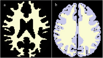
Figure 1. DICOM MR dataset of (a) Transverse section of white matter and (b) Transverse section of combined white/grey matter were used to create STL 3D- printable files.
Download figure:
Standard image High-resolution image2.4. MRI scanner
A MAGNETOM Prisma 3.0 T MRI scanner (Siemens Healthcare, Erlangen, Germany) with Siemens NUMARIS/4 scanner software and a Radiofrequency head coils (RF coils) of 20 channels were used in this study, Syngo (Version MR E 11) was used to view the MRI images .
2.5. T1-relaxation time measurement
After applying a localizer sequence, T1-relaxation time measurements were carried out using a saturation recovery method with fast low angle shot magnetic resonance imaging sequence (FLASH sequence). The FLASH sequence was used with the following parameters: slice thickness = 3 mm, echo time (TE) = 2.49 m, FoV read = 183 mm, FoV phase = 25%, number of averages = 6 and the repetition time (TR) ranges were chosen from 250 ms to 5000 ms. T1-weighted relaxation times of four different types of PORO-LAY material were measured in 27 consecutive scans using Siemens NUMARIS/4 scanner software with various measuring areas ranging from 0.13 to 0.28 cm2. A constant echo time of TE = 2.49 ms was maintained and the MRI images were acquired by stepwise increasing repetition time (TR) values starting from 250 ms to 1000 ms, with 100 ms increments, 1000 ms to 3000 ms with 250 ms increments and 3000 ms to 5000 ms with 500 ms increments. The total experiment time was five hours and 13 min T1-relaxation time values of all samples were obtained by chosing random selected regions of interest (ROIs). Hereby, the signal intensities of the chosen regions were treated with non-linear least square fit method. Curves were fitted to the individual data points of signal integrals at the preselected TR based on equations from [25–27]:

2.6. ROIs selection
All four different materials were scanned. Regarding each material, three slices inside the cubes and within each slice, three randomly selected areas were chosen. This resulted in a total of nine ROIs as circles with varied areas from 0.13 to 0.28 cm2 with a mean value of 0.20 cm2 for each material.
2.7. Dielectric spectrometer
A high-resolution dielectric spectrometer with a broadband dielectric converter constructed by Novo-control Technologies GmbH (Montabaur, Germany) was used to measure the electrical permittivity and the electrical conductivity of the post-washed printed samples. All four different types of PORO-LAY materials were prepared in disks of 3 mm diameter and 2 mm thickness and were measured at a frequency range from 3 MHz—1.8 GHz at room temperature.
3. Results
3.1. T1-relaxation times of PORO-LAY materials
T1-relaxation times of PORO-LAY filaments were acquired by 3.0 T MRI scanner with use of a 20 channel head coil and FLASH sequence. Table 2 shows a diversity in the values of the acquired T1-relaxation times expressed as mean ± standard deviation (SD) for all types of PORO-LAY filaments (LAYFOMM 40, LAYFOMM 60, LAY-FELT and GEL-LAY) at 100% infill density.
Table 2. T1-weightd relaxation time of all types of PORO-LAY materials.
| PORO-LAY materials | T1-Relaxation time (msec) Mean ± SD |
|---|---|
| LAYFOMM 40 | 676 ± 54.7 |
| LAYFOMM 60 | 454 ± 28.5 |
| LAY-FELT | 1044 ± 68.3 |
| GEL-LAY | 545 ± 32.6 |
3.2. Simple, complex and multi-materials 3D-printing shapes using PORO-LAY materials and the associated T1-weighted MR image.
A KISS 200 extended 3D-FDM printer with dual extruders was used to print the produced STL files of white and combined white/grey matter segmented from DICOM MRI dataset. Furthermore, a MAGNETOM Prisma 3.0 T MRI scanner with radiofrequency head coils of 20 channels were used to acquire the T1-weighted MRI image of simple and complex 3D-printed shapes of PORO-LAY materials.
Figure 2 shows the T1-weighted MR image of all 100% infill density cubic shaped PORO-LAY materials in 50 ml distilled water falcon tube. All PORO-LAY materials produced MR signal with visible contrast and different grey levels compared to the sponge that shows no contrast. Due to its low dimensional stability after dissolving the PVA component, GEL-LAY was excluded from the next study.

Figure 2. The acquired T1-weighted MR image of all PORO-LAY filaments and kitchen sponge using T1/FL2D sequence. © [2019] IEEE. Reprinted, with permission, from [23].
Download figure:
Standard image High-resolution imageFigures 3 and 4 present a schematic flowchart of the process of slicing, printing and subsequent acquiring T1-weighted MR image of realistic complex printed shapes of LAYFOMM 40 and LAY-FELT materials using STL files. All were produced from the segmented MR DICOM dataset of white and grey matter structures.
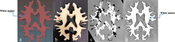
Figure 3. (a) Transversal plan shape of the segmented white matter STL file (b) Printed complex shape of LAYFOMM 40 with 10 mm thickness (c) Transversal plan of the acquired T1-weghited MR image using T1/FL2D sequence, room temperature water was used to dissolve the PVA component for three days (d) Transversal plan of the acquired T1-weghited MR image using T1/FL2D sequence, hot tap water with temperature of 50 °C was used was used to dissolve the PVA component for three days.
Download figure:
Standard image High-resolution image
Figure 4. (a) Transversal plan shape of the segmented combined white/grey matter STL file (b) Printed complex shape of LAYFOMM 40 as white matter and LAY-FELT as grey matter with 10 mm thickness (c) Transversal plan of the acquired T1-weghited MR image using T1/FL2D sequence, hot tap water with temperature of 50°C was used to dissolve the PVA component for three days.
Download figure:
Standard image High-resolution imageIn figure 3, LAYFOMM 40 (with infill density of 100% and rectilinear infill pattern) was used to mimic the shape and the contrast of the white matter. Figure 3(c) shows the acquired T1-weghited image after placing the printed structure in a room temperature water bath. While figure 3(d) shows the T1-weighted image of the same printed structure after placing it in a hot water bath with temperature of 50 °C. The differences in the produced homogeneity in the acquired MR image have been discussed.
In figure 4, LAYFOMM 40 (with infill density of 100%) and LAY-FELT (with infill density of 100%) were used to print a combined white/grey matter. Figure 4(a) shows the STL file of the segmented transversal section of white/grey matter from DICOM MR dataset, figure 4(b) shows a complex multi-materials 3D printing structure using two different materials with different hardness. Figure 4(c) shows the acquired T1-weighted image of the printed structure, the produced inhomogeneities indicated by red arrows, have been discussed too.
3.3. Dielectric properties of PORO-LAY materials
A dielectric spectrometer with a broadband dielectric converter was used to acquire the values of electrical permittivity and electrical conductivity of the printed 3.0 × 2.0 mm disks of PORO-LAY materials at a frequency range from 3 MHz–1.8 GHz at room temperature. All are shown in figure 5 and summarized in table 3. The dashed red lines in this figure show the values of permittivity and conductivity of all PORO-LAY materials at 127.728 MHz in the 3.0 T MRI scanner.

Figure 5. Permittivity (F/cm) and conductivity (S/cm) measurements as functions of frequency (MHz) for different printed types of PORO-LAY materials including LAYFOMM 40, LAYFOMM 60, LAY-FELT and GEL-LAY for a wide range of magnetic field strength. The dashed red lines show the values of permittivity and conductivity at 127.728 MHz for 3.0 T MRI scanner.
Download figure:
Standard image High-resolution imageTable 3. The permittivity and conductivity values of PORO-LAY materials measured at 127.728 MHz at room temperature for 3.0 T magantic field strength.
| PORO-LAY filaments | Permittivity εr (F cm−1) | Conductivity σ (S cm−1) |
|---|---|---|
| LAYFOMM 40 | 26.7 | 2.30E-04 |
| LAYFOMM 60 | 16.1 | 9.50E-05 |
| LAY-FELT | 17.1 | 7.40E-05 |
| GEL-LAY | 26.8 | 2.50E-04 |
4. Discussion
This study investigated the T1-relaxtation time values, a central issues in MR contrast investigations [28], the dielectric properties and MR image visible contrasts of 3D printable multi-materials complex shapes of PORO-LAY filaments. The results from different PORO-LAY materials types namely LAYFOMM 40, LAYFOMM 60, LAY-FELT and GEL-LAY shown in table 2, reveals variations in T1-relaxtation time values expressed in mean ± standard deviation as T1 = 676 ± 54.7 ms,T1 = 454 ± 28.5 ms, T1 = 1044 ± 68.3 ms and T1 = 545 ± 32 ms, respectively.
The differences in T1-relaxtation time values of these materials are caused by the differences in hardness, elasticity and porosity of these materials. Regarding this, LAYFOMM 40 and LAYFOMM 60 are identical materials and only have a difference in shore hardness. Compared to LAYFOMM 40 (A40), LAYFOMM 60 has a higher shore hardness of A60 and therefore, reveals an expected shorter T1-relaxation time. With respect to the T1-relaxation time for GEL-LAY and LAY-FELT, both have identical properties except the porosity. According to the manufacturers-product specifications [29], the LAY-FELT material contains soft felt-fibers with less porosity but more elasticity. In contrast to the GEL-LAY material which is highly porous, the printed objects are very unstable and less elastic. Hence, the T1-relaxation time of LAY-FELT is expected to be much longer than GEL-LAY.
The acquired T1-relaxation times of the investigated materials were close to the T1-relaxation time values of some soft tissues and organs in the human body reported by Bojorquez et al [30] and summarized in table 4.
Table 4. Some of T1-relaxation times in the human body at 3.0 T. Reprinted from [32], Copyright (2017), with permission from Elsevier.
| Tissue | T1-relaxation times (ms) |
|---|---|
| Gray matter | 1193 ± 65 |
| White matter | 781 ± 61 |
| Fat | 450 ± 26 |
| Fibrogladular tissue | 1324 ± 168 |
| Bone marrow | 586 ± 12 |
| Cartilage | 1201 ± 41.1 |
| Cerebellum | 1081 ± 35 |
| Intervertebral disc | 1201 ± 41.1 |
| Kidney (cortex) | 1168 ± 27.2 |
| Muscles | 1232 ± 255 |
| Nerve | 1083 ± 31 |
| Trachea | 1201 ± 41.1 |
| Myocardium | 1169 ± 45 |
In many previous studies, different kinds of printable and non-printable materials were used as a TMMs for MRI phantoms and their T1-relaxation time values are summarized in table 5. Hereby, e.g. vegetable oil and Silicone oil with T1-relaxation time of 405 ± 15 ms and 1515.8 ± 105 ms are common fluids which were used to mimic fat and fibrogladular tissues in MRI phantoms [31, 32]. However, these materials are not printable and they cannot be used for phantoms of complex geometries.
Table 5. Some of T1-relaxation time values of printable and non-printable materials used in MRI phantoms and their limitations. Reproduced from [36]. CC BY 4.0.
| Material | T1-relaxation time ( ms) | Limitations |
|---|---|---|
| Vegetable oil | 405 ± 15 | Molding |
| Silicone oil | 1515.8 ± 105 | Molding |
| Polyvinyl chloride (PVC) | 206.81 ± 17.50 | Molding |
| Polylactic acid (PLA) | N/A | No MR signal |
| Acrylonitrile butadiene styrene (ABS) | N/A | No MR signal |
| High Temperature (RGD-525) | N/A | No MR Signal |
| Poly(methyl methacrylate) ( PMMA) | N/A | No MR Signal |
| FullCure 720 polymer | N/A | No MR Signal |
| Epoxy resin | N/A | No MR Signal |
Also Polyvinyl chloride (PVC), a commonly used tissue mimicking material for MRI thoracic phantoms, does not provide the proper in vivo MR properties. It bears a low T1-relaxation time value (206.81 ± 17.50 ms) , and is not available as filaments for 3D printing [34].
On the other hand, Polylactic acid (PLA), Acrylonitrile butadiene styrene (ABS), High Temperature (RGD-525), Poly(methyl methacrylate) (PMMA) and FullCure 720 polymer are available as 3D printable material, but they send no MR signal. Hence the use is only limited to print the molds of MRI phantom [31] with a technique that is limited to construct simple geometrical shapes phantoms [33].
In contrast to all mentioned above, PORO-LAY materials such as LAYFOMM 40, LAYFOMM 60, LAY-FELT and GEL-LAY provide a diversity in T1-relaxation time values, including a T1-relaxation time to be close to human tissues. Hence, besides the advantage to bear in vivo MR properties, PORO-LAY materials provide diameters of 1.75 mm and 3.00 mm and are available as printable filaments. With the use of 3D-FDM printing techniques, they offer the opportunity to realize realistic shapes of human tissues and organs, especially, the white and grey matter.
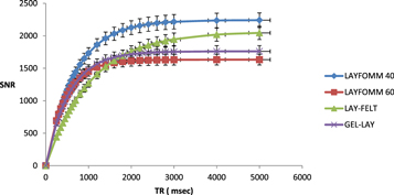
A further important finding is that compared to other 3D-printable materials, PORO-LAY as a flexible filaments, offer a higher signal to noise ratio (SNR) as well as a T1 type related better contrast.
In this study, the magnatic charactrisitics related T1-relaxation time is calculated by the signal to noise ratio SNR course of the objects. Figure 6 shows the SNR versus repetition times (TR) of PORO-LAY materials and the resulted mono-exponential T1-relaxation time behavior from all ROIs, that are in good agreement with reported in-vivo measurements results from soft tissues in human body [35].
Figure 6. Signal to noise ratio (SNR) versus repetition times (TR) ranges from 0 to 5000 msec for all types of PORO-LAY materials .
Download figure:
Standard image High-resolution image
The results of this study also have been evaluated regarding to the acquired grayscale level in the T1-weighted image. Figure 2 shows a T1-weighted image of cubic printed shapes of PORO-LAY materials, LAYFOMM 40 was associated with high signal intensity compared to a low signal intensity for LAY-FELT, which was within the expectation as LAYFOMM 40 has a short T1-relaxtion time of 676 ± 54.7 ms, while LAY-FELT has the highest T1-relaxation time of 1044 ± 68.3 ms. Hence, the visible contrast between these two materials, due to the variations in the T1-relaxtion values, could be employed in multi-materials additive manufacturing processes.
Traditional mold phantoms which have been constructed by several researches to validate MRI systems have some limitations, e.g. the realistic multi-material complex structures of the human tissues cannot be replicated. In consequence, the evaluation of imaging systems is often limited with their use [33]. In this study, the alternatives to print realistic multi-material complex shape using PORO-LAY filaments have been evaluated too. Figure 3 shows the process of using LAYFOMM 40 (T1 = 676 ± 54.7 ms) to mimic the shape and T1-relaxtion time of white matter (T1 = 781 ± 61 ms). Moreover, a dramatic improvement in the homogeneity of the acquired MR image has been achieved after using hot tap water to dissolve the soluble PVA component (figures 3(c) and (d)).
In addition, LAYFOMM 40 and LAY-FELT were used to mimic the shape, desired visible contrast as well as T1-relaxtion time values of the combined white/grey matter of the human brain. Figure 4(b) shows the printed structure of LAYFOMM 40 and LAY-FELT as a multi-material complex shape with thickness of 10 mm. LAYFOMM 40 (T1 = 676 ± 54.7 ms) was used to mimic the white matter (T1 = 781 ± 61 ms), the grey matter (T1 = 1193 ± 65 ms) has been mimicked using LAY-FELT (T1 = 1044 ± 68.3). The acquired MR image in figure 4(c) shows clear visible contrast, due to the variations in their T1-relaxtion values, between LAYFOMM 40 and LAY-FELT. The inhomogeneities shown in figure 4(c), indicated by red arrows, are caused by the remnant unwashed PVA component. PVA shows no MR signal and any undissolved PVA material will appear as black holes in the MR image. However, the PVA dissolvability can be improved by increasing the water bath temperature and duration. Further studies should be done to investigate the thermal effects of PORO-LAY materials for multi-materials complex printed shapes.
A further relevant issue, frequently noted at high fields (3.0 T and above), are dielectric effects caused by B1 field inhomogeneities which leads to shading artifacts. Up to now, most available MRI commercial phantoms are water or saline solution based. Water has high permittivity and low conductivity while saline solution has high permittivity and moderate conductivity [36]. Due to their high permittivity values, which is a potential source of image artifacts [37], these fluids are not well suitable for MRI imaging. In which degree the dielectric resonances cause the artifacts remain controversial but it should be minimal as possible [38, 39]. To our knowledge, no study in the literature has discussed the dielectric properties of flexible and sponge 3D-FDM printable materials like PORO-LAY filaments thus far [18, 40, 41].
In our study, the values of permittivity and conductivity of PORO-LAY materials at a frequency range from 3 MHz–1.8 GHz at room temperature were measured (figure 5). The results show that the values of permittivity and conductivity of LAYFOMM 40, LAYFOMM 60, LAY-FELT and GEL-LAY measured at 3.0 T (127 MHz) (table 3), are in good agreement with the course of the permittivity and conductivity at low frequency ranges. Compared to very high fields, the low permittivity and conductivity in this operating magnetic field strength (∼3 T) assure minimum artifacts. Hence, our results demonstrate that compared to pure water and saline solutions, which at room temperature have high permittivities of 80 F cm−1 [42] and 67 F cm−1 [43], respectively, the lower permittivity and conductivity values of PORO-LAY lead to reduced MR image artifact and thus makes it more suitable for MRI applications.
This study successfully measured the T1-relaxation time and the dielectric properties of PORO-LAY materials. By revealing MR properties close to human tissues and the ability to be used in single and multi-material additive manufacturing processes, these materials show crucial properties to be a preferred phantom material candidate to mimic human brain tissues within MRI examination.
Nevertheless, the findings are subject to some limitations. The study was not specifically designed to evaluate the mechanical and thermal properties of PORO-LAY materials, such as elastic modulus, tissue strength and the optimal temperature for the water bath to dissolve the PVA component completely. Examining these features could provide an idea of their mechanical and thermal characteristics and allow more detailed comparisons to most of human tissues and organs as well as other 3D-printable materials.
Moreover, there are certain drawbacks of using 3D printing techniques for the construction of complex multi-materials structures [18, 33]. Increasing the thickness of the printed object might prevent a complete PVA dissolvability. However, using different printing settings might speed up the dissolvability of PVA components to minimize these artifacts.
A further study on a 3D-printed brain phantom should be conducted with a focus on using PORO-LAY materials with different printing settings such as infill density, infill pattern to produce an excellent homogenous MR image.
5. Conclusion
The present study investigated, evaluated and characterized MR medical imaging relevant T1-relaxation time and dielectric properties of various types of a new experimental material composed of printable rubber-elastomeric polymer and PVA components called PORO-LAY. Beside the advantages of being low cost, the resulted T1-relaxation time, permittivity, conductivity values as well as their feasibility to be printed in multi materials 3D-complex shapes demonstrate that these materials could be used as TMMs and offer a great potential for designing novel phantoms for MRI applications.
Acknowledgments
This work is partially based upon experiment performed at the Dielectric Spectroscopy instrument operated by JCNS-1, we would like to thank Dr. Reiner Zorn for his help with the scanning of our samples. The authors acknowledge financial support by the Federal Ministry of Education and Research of Germany in the framework of the Palestinian-German Science Bridge (BMBF grant number 01DH16027).