
Abstract
Quenched and tempered S960QL (yield strength ≥ 960 MPa) ultra-high strength steel (UHSS) thick plates were joined by multi-pass robotic gas metal arc welding (GMAW) using weaving and stringer bead techniques. The effects of microstructural changes in heat-affected zone (HAZ) of the joint on toughness and hardness were examined. Weaving and stringer bead techniques applied for the multi-pass welding procedure altered average peak temperatures and exposure time to those temperatures. Mechanical properties of HAZs were evaluated by utilizing notch impact and hardness tests, and these results were correlated with microstructural characterizations using optical (OM) and scanning electron microscopes (SEM). Prior austenite grain (PAG) coarsening occurred because of increased exposure time to peak temperature in coarse-grained HAZ (CGHAZ) of the W-5 (weaving pass) joint. CGHAZs at the face pass, which have not been subjected to a second thermal cycle, have the highest hardness in both joints. Hardness of SCHAZ and CGHAZ of S-12 joint was 7% and 1% higher compared with W-5 joint, respectively. Weld metal hardness of W-5 joint was 15% lower than that of S-12 joint. Both joints not only fulfilled the requirements of minimum 50 J per EN ISO 10025-6 at −20 °C but exceeded this limit by 50% (W-5) and 200% (S-12). Lateral expansions for impact toughness specimens were around 17.5% for S-12 joint, whereas it was 4% for W-5 joint. Since HAZ in the S-12 (stringer bead) joint is narrow compared with the one in the W-5 joint, impact toughness values were higher with the S-12 joint due to the locations of the notches of the impact specimens.
Export citation and abstract BibTeX RIS

Original content from this work may be used under the terms of the Creative Commons Attribution 4.0 licence. Any further distribution of this work must maintain attribution to the author(s) and the title of the work, journal citation and DOI.
1. Introduction
In addition to pressure vessels, pipelines, offshore and shipbuilding industries, vehicles (especially cranes and trucks), and transportation industries have taken advantage of UHSS, which are generally characterized by high mechanical properties, formability, and weldability. These steels gain these properties by microalloying elements such as Cr, Mo (added in order to move the CCT diagram to the right), Ti, Nb, and V (added in order to obtain precipitation hardening and grain refinement) and different techniques such as thermo-mechanically controlled processing and quenching and tempering (Q+T) [1–3].
As a manufacturing technique, welding has always been quite important for joining metal parts in the previously mentioned industries. Weight reduction via UHSS has always been one of the automotive industry's main concerns to reduce fuel consumption and exhaust gas pollution. Even though the future might yield the electrification of vehicles, weight reduction while maintaining crash safety will be crucial to extend the range and improve braking and cornering performance. Many researchers have researched welding of advanced and ultra high strength steels. While some investigated weld metal properties and microstructures, others focused on the HAZ.
Sisodia and Gáspár [4] investigated mechanical strength and microstructure of weld metal and HAZ of multi-pass gas metal arc welded S960QL. They observed microstructure of relatively coarse lath martensite in CGHAZ and mixture of tempered martensite and M/A constituents in ICHAZ. Tumer et al [5] studied multi-pass MAG welding of S1100MC UHSS in PA (flat) and PF (vertical upwards) positions using matching filler wire and they noted that HAZ microstructure of the last pass was mainly hard martensite due to high cooling rate. Subsequent welding passes yielded necklace type M/A constituents and bainitic microstructure in reheated HAZ of prior passes. In other studies of these researchers [6, 7], they employed undermatching wire in order to join S1100MC base metal using GMAW in different joint positions (namely, PA and PF). Since heat input and cooling time changed in different joint positions, this affected the size of HAZ and it was smaller in PA compared with PF due to weaving and less average peak temperature exposure. Łomozik [8] researched microstructure, toughness and hardness of HAZ of S1100QL steel welded with MAG process utilizing metal cored wire and in addition he also performed simulation tests using Gleeble 3500 simulator. He observed different HAZ microstructures (i.e., from martensite to mixture of martensite, bainite and small amounts of ferrite) depending on thermal cycles. Experimental studies on heat input and cooling rates in HSLA and UHS steels were not limited to open air conditions. Cooling conditions underwater were also investigated. Tomków et al researched wet welding of S460N high strength low alloy (HSLA) steel utilizing SMAW [9, 10] and they investigated cold cracking phenomenon and the effect of temper bead technique on susceptibility of this steel to cold cracking. They noted significant decrease of hardness in HAZ using temper bead. They also concluded similar results for underwater wet welding of S460ML and S460N HSLA steels [11] and shielded metal arc welding (SMAW) of S1300 UHSS and obtained a drop of 40–100 HV10 hardness in HAZ [12]. Researchers also utilized GMAW [13] for the same base metal and they pointed out that underwater welded sample resulted in coarse grained martensitic microstructure and showed high brittleness. In another research by Tomków et al [14] application possibilities of S960 UHSS in underwater welded structures were investigated using manual metal arc (MMA) welding utilizing three different heat inputs. They proved this UHSS base metal is quite sensitive to heat input and both low (0.63 kJ mm−1) and high (0.93 kJ mm−1) heat inputs led to formation cracks in HAZ and they found lowest number of cracks with the middle heat input (0.72 kJ mm−1) and also observed the relationship between high heat input and low hardness in HAZ. Gáspár [1] simulated HAZ areas and toughness properties of S960QL steel in a Gleeble physical simulator. He noted that HAZ indicated higher sensitivity to heat input than conventional structural steels. Physical simulation studies revealed the beneficial effect of post-weld heat treatment, especially on intercritical HAZ toughness of quenched and tempered steels [15]. Kim et al researched fatigue crack growth behavior of simulated HAZ of 800 MPa grade steel using a Gleeble physical simulator. They concluded that the fatigue crack growth rate of coarse-grained HAZ was higher than fine-grained HAZ. They added that fatigue crack growth was the fastest in this region because of the very high martensite–austenite (M/A) constituent in inter-critically reheated coarse-grained HAZ [16]. Other researchers also used Gleeble physical simulator to understand the effect of t8/5 cooling time on S960MC steel's HAZ properties. Their results showed that increasing t8/5 time decreased hardness, yield, and tensile strength; on the contrary, decreasing t8/5 time resulted in higher absorbed Charpy energy [17]. Maurer et al investigated the effects of different factors (i.e., filler metal, welding parameters, weld seam preparation) on HAZ softening in gas metal arc welding of TMCP steel S700MC using different filler wires. They concluded that lower heat input and overmatching filler metal positively affected strength [2]. Xiong et al [18] investigated the contribution of intragranular acicular ferrite on crack initiation and propagation in HAZ of two different steels (i.e., Al and Ti killed and smelted with different methods), both of which had around 570 MPa yield and 670 MPa tensile strengths and 22% elongation, using Gleeble thermo-mechanical simulator. They concluded that steel containing intragranular acicular ferrite was better at impact toughness below −20 °C and had a greater ductile fracture zone, and its crack initiation and propagation energies were higher. Lomozik [8] simulated the HAZ of S1100QL steel using the Gleeble simulator. His simulations included single and double thermal cycles and t8/5 cooling times. In order to obtain the optimal combination of high toughness and hardness, the researcher recommended a single thermal cycle for all cooling times and Tmax1 = 1250 °C + Tmax2 = 900°C double thermal cycle with t8/5 = 5 s and 10 s cooling times up to four repetitions of heating. Celin et al [19] investigated multi-pass welding of S690QL high-strength steel and microstructural variations in HAZ. They also simulated different HAZ microstructures using a dilatometer and compared them with the experimental ones. Gáspár et al [20] researched physical simulations to optimize the welding process for sufficient HAZ toughness of gas metal arc welded S960QL quenched and tempered steel. They mentioned that in multi-pass welding, CGHAZ, intercritical HAZ (ICHAZ), and inter-critically reheated coarse-grained HAZ (ICRCGHAZ) were the most critical areas. Researchers also noted grain size of CGHAZ was ten times (or more) larger than fine grains of quenched and tempered base metal. This situation yielded low-impact energy along with martensitic microstructure. Amraei et al [21] researched mechanical properties and microstructure of HAZ of two ultra high strength steels (i.e. with 960 and 1100 MPa yield strengths) using Gleeble 3800 simulator. S1100 did not show much HAZ softening. On the other hand, S960 indicated considerable HAZ softening (upto 32%).
Kumar et al [22] also investigated the effect of single and multiple thermal cycles on the microstructure and mechanical properties of HAZ of low-carbon bainitic steel using a Gleeble thermomechanical simulator. They applied different peak temperatures with 50 kJ cm−1 heat input for single and two-pass welds. Sisodia and Gáspár [23] utilized a Gleeble physical simulator with Rykalin 3D model. They applied different cooling times to examine HAZ areas (SCHAZ (subciritical HAZ), ICHAZ, FGHAZ (fine-grained HAZ), CGHAZ) in S960QL and S960M high-strength steels. Lee et al [24] investigated the effect of martensite-austenite constituent (M/A) on crack initiation and propagation in ICHAZ of 500 MPa yield strength HSLA steel using a thermal cycle simulator. They performed detailed microstructural analyses and examined crack initiation and propagation behavior using bending tests and EBSD analyses. Falkenreck et al [25] investigated phase transformations of high-strength armor steel for different t8/5 cooling rates starting from 3 s to 240 s. Using dilatometry, they analyzed different HAZ regions such as coarse grain HAZ, fine grain HAZ, intercritical HAZ, and subcritical HAZ. Researchers also validated their simulated microstructure results by employing real hybrid laser-arc welding. Another study by Gáspár et al [26] studied HAZ hardening and softening of three different dual-phase steels used in the automotive industry. They simulated welding thermal cycles that may correspond to TIG welding of DP steels using a Gleeble 3500 thermomechanical simulator. Their samples were heated to different peak temperatures and cooled at two different times, and later, they investigated the hardness and microstructures of the specimens. They noted the highest HAZ softening in fine-grained and intercritical HAZ regions. Li et al [27] performed thermal simulations using Gleeble 3800 to understand the effect of prior austenite grain size on the size of M/A constituent and toughness in Nb micro alloyed 700 MPa pipeline steel. They noted that the coarser austenite grain size, the coarser was M/A constituent and the lower HAZ toughness. Similarly, they concluded that fine PAG size and a small M/A constituent resulted in high toughness. Ramachandran et al [28] researched combined effect of bainitic microstructures with M/A constituent on CGHAZ toughness of TMCP HSLA steel with 580 MPa yield strength implementing three different heat inputs by Gleeble 1500 thermal simulator. They noted that toughness decreased because of the formation of M/A constituents with an increase in heat input. In CGHAZ, M/A constituent was mostly martensitic with a small fraction of retained austenite. Moon et al [29] simulated CGHAZ of HSLA steel using Gleeble 1500 simulator and researched the effect of thermo-mechanical cycles on the microstructure and strength of lath martensite in CGHAZ. Rak and Treiber [30] realized narrow gap multi-pass submerged arc welding of quenched and tempered (Q+T) HSLA steels with equal and different strength levels. They examined toughness values with Charpy and CTOD tests. In another study, two thermo-mechanically controlled processes (TMCP) and one Q+T steel were welded using a two-pass MAG welding method with four different heat inputs [31]. Researchers found that Q+T steel was more prone to HAZ embrittlement than TMCP steels. They explained this phenomenon by microstructural analyses, which revealed carbide concentration in combination with coarse bainitic structure in HAZ of Q+T steel.
Most of the research in the literature on UHSS are based on thermomechanical simulators rather than actual welding. Researchers, who studied experimental welding of UHSS generally investigated the effect of different heat inputs (via altering welding parameters) and cooling conditions (open air or underwater) on mechanical properties and the microstructure.
In this study, multi-pass welding of S960QL ultra-high strength steels in V-groove butt configuration has been realized. Furthermore, the effect of different heat inputs by applying different techniques (weaving and stringer passes) on HAZ microstructure and mechanical properties have been investigated for the first time in the literature.
2. Experimental
2.1. Material, consumables, and joint design
Base metals (EN 10025-6 S960QL, SSAB) [32] with dimensions of 15 mm×150 mm x 400 mm were machined to have a bevel angle of 30°. A backplate of the same material was utilized, and a 6 mm root opening was kept to form a joint of 60° V-groove. Two coupons, one with 12 stringer passes and one with 5 passes (1 stringer root pass+4 weaving passes), were gas metal arc welded in PA position (85° torch in push position) with OTC Daihen FD-V8L robot and GekaMac P500L water-cooled inverter power supply using 1.2 mm diameter solid wire (EN ISO 16834-A: G 89 6 M21 Mn4Ni2CrMo; AWS A5.28: ER120S-G) [33] and Ar + 18% CO2 shielding gas (M21; EN ISO 14175) [34] with a flow rate of 15 l.min−1. The SEM microstructure of the base metal is given in figure 1. According to EN ISO 16834 [33], welds shall be performed in temperatures ranging from 120 °C to 180 °C, except for the first layer, which may be welded without preheating. Therefore, base metals were welded at room temperature, and interpass temperatures were kept around 150 ± 15 °C. Tables 1 and 2 present the chemical compositions and mechanical properties (based on the manufacturer's data sheet) of the base metal and the filler wire. Figure 2 shows joint designs and weld passes for coupons for 12 stringer and 5 weaving passes. Welding parameters were determined based on bead on plate trials, experience and thickness of the base metals. Table 3 presents the process parameters employed. Welded coupons are given in figure 3.

Figure 1. SEM microstructure of S960QL base metal.
Download figure:
Standard image High-resolution imageTable 1. Chemical compositions of base metal and filler metal (wire) (% wt max) [35, 36].
| Elements | Base metal | Filler wire |
|---|---|---|
| C | 0.20 | 0.10 |
| Si | 0.50 | 0.80 |
| Mn | 1.60 | 1.80 |
| Cr | 0.80 | 0.35 |
| Ni | 2.00 | 2.25 |
| Cu | 0.30 | — |
| Mo | 0.70 | 0.60 |
| B | 0.005 | — |
Table 2. Mechanical properties of base metal and filler wire [35, 36].
| Base/Filler | Yield Strength Rp0.2 (min.) (MPa) | Tensile Strength Rm (min.) (MPa) | Elongation A (L0 = 5d0) (min.) (%) | Impact Energy Charpy ISO-V (min.) (J) | |
|---|---|---|---|---|---|
| Base metal | 960 | 980–1150 | 12 | 40 (−40 °C) | |
| Filler wire | 915 | 960 | 20 | 130 (+20 °C) | ≥47 (−60 °C) |
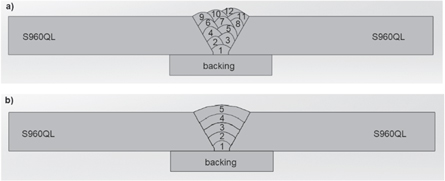
Figure 2. 60° V-groove with 6 mm root gap joint design and weld passes. (a) 12 stringer passes (without weaving) (denoted as S-12). (b) 5 weaving passes (denoted as W-5).
Download figure:
Standard image High-resolution imageTable 3. Process parameters employed (in detail).
| Pass | Current (A) | Voltage (V) | Welding speed (mm.min−1) | Weaving (Left,Right) (mm) | Nominal Heat Input (kJ.mm−1) | Average Nominal Heat Input per Pass (kJ.mm−1) | Total Nominal Heat Input (MJ) | |
|---|---|---|---|---|---|---|---|---|
| Weaving pass (W-5) | 1 | 290 | 31 | 250 | N/A | 2.16 | ||
| 2 | 309 | 28.7 | 200 | 4,4 | 2.66 | |||
| 3 | 280 | 32 | 200 | 6,6 | 2.69 | 2.58 | 5.16 | |
| 4 | 280 | 32 | 200 | 8,8 | 2.69 | |||
| 5 | 293 | 30.6 | 200 | 11,11 | 2.69 | |||
| Stringer pass (S-12) | 1 | 272 | 33.1 | 250 | 2.16 | |||
| 2 | 283 | 31.9 | 500 | 1.08 | ||||
| 3 | 279 | 32.3 | 500 | 1.08 | ||||
| 4 | 285 | 31.2 | 450 | 1.19 | ||||
| 5 | 292 | 30.8 | 450 | 1.20 | ||||
| 6 | 311 | 28.5 | 550 | N/A | 0.97 | 1.14 | 5.47 | |
| 7 | 310 | 28.6 | 550 | 0.97 | ||||
| 8 | 292 | 31.2 | 550 | 0.99 | ||||
| 9 | 291 | 30.7 | 550 | 0.97 | ||||
| 10 | 288 | 31.2 | 550 | 0.98 | ||||
| 11 | 291 | 30.8 | 550 | 0.98 | ||||
| 12 | 302 | 29.3 | 500 | 1.06 |

Figure 3. Coupon welded with 12 stringer passes (a). Coupon welded with 5 weaving passes (b).
Download figure:
Standard image High-resolution image2.2. Microstructural and mechanical characterization
Mechanical characterizations were realized by microhardness, and Charpy V- impact tests. Three specimens were machined according to EN ISO 148-1 [37] for Charpy V- notch impact tests. The notched face was machined through thickness of weld joints (figure 4). Impact test specimens extracted from HAZ were tested at −20 °C according to EN ISO 9016 [38] using Zwick Roell RKP 300 pendulum impact tester. EMCOTEST Durascan-70 G5 was utilized for Vickers microhardness measurements according to EN 6507-1 [39] and EN 9015-2 [40] with 9.806 N load (HV1). The gap between two consecutive hardness measurement points in a perpendicular position was 0.25 mm. The distance for hardness measurement lines from face side and root sides of the joints were 2 mm.
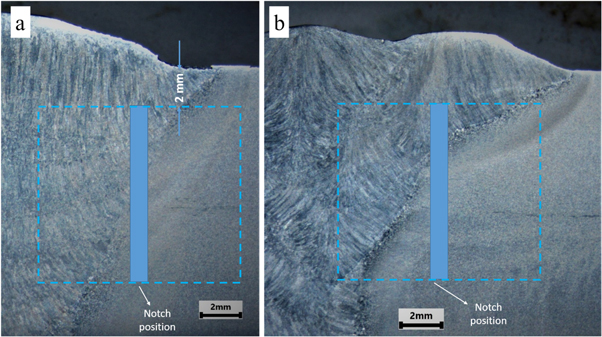
Figure 4. Notch position and locations of impact test specimens. (a) W-5, (b) S-12.
Download figure:
Standard image High-resolution imageMicrostructural characterization specimens extracted from the coupons were ground using SiC papers and polished using 3 μm and 1 μm diamond compounds. Marshall's reagent and Nital3 solutions were the etchants for polished surfaces. Optical microstructure images were gathered using LEICA DMi8 optical microscope (OM), and macro images were obtained with Nikon SMZ745T. In addition to OM, Zeiss EVO LS10 Scanning Electron Microscope (SEM) was utilized to characterize different HAZ regions.
3. Results and discussion
3.1. Microstructure
Figure 5 shows CGHAZ located between FGHAZ and weld metal (WM). Figures 6, 7, and 8 illustrate the HAZ subregions, namely CGHAZ, FGHAZ, and ICHAZ, respectively [41]. Next to the fusion line, austenite formation has re-occurred because the material is heated well above the Ac3 temperature, and the oriented microstructure obtained by thermomechanical rolling has become coarser equiaxed austenitic grains (figure 5). The CGHAZ microstructure of S960QL consists of martensite and tempered martensite in both conditions. Martensite predominates with coarser prior austenite grains in the CGHAZ of W-5. The weaving reduces the peak temperature at the CGHAZ of the W-5 joint (figure 6). However, the exposure time to peak temperature supported PAG growth in the W-5 CGHAZ. Despite lower peak temperatures, slow cooling time due to weaving resulted in coarser PAGs in the W-5 joint, whereas the S-12 joint had finer PAGs due to less exposure time. Both peak temperature and exposure time are crucial for grain coarsening of PAG in UHS steels [5]. It has a dominant effect on austenitization during heating. Then the regenerated austenite grains affect the phase transformation products during the cooling period, which depends on the applied heat inputs. As the microstructures of the HAZ subregions of the weld metals obtained for both joints are compared, no significant difference can be observed. However, the sizes of the regions vary according to the peak temperatures and their exposure time. As shown in figures 7(a) and (b), the microstructure of FGHAZ consists of martensite within blocks of quite small PAG. This microstructure contributes greatly to the excellent balance of high strength and toughness [42]. The ICHAZs of both welds show the presence of unaltered islets in the microstructure of the base material between a chain of partially transformed austenite, martensite, and some tempered martensite formed by partially nucleated grains along the PAGs (figures 8(a) and (b)).

Figure 5. CGHAZs are located between FGHAZ and WM. (a) W-5, (b) S-12.
Download figure:
Standard image High-resolution image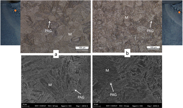
Figure 6. CGHAZ of W-5 (a) and S-12 (b).
Download figure:
Standard image High-resolution image
Figure 7. FGHAZ of W-5 (a) and S-12 (b).
Download figure:
Standard image High-resolution image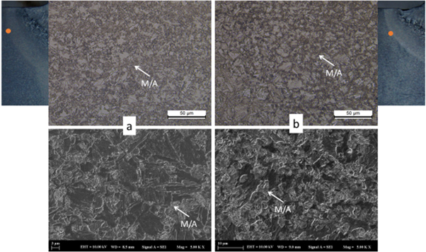
Figure 8. ICHAZ of W-5 (a) and S-12 (b).
Download figure:
Standard image High-resolution imageIn the multi-pass joining of UHSS, ICR-CGHAZ shows noticeable microstructural changes in the HAZ. The coarse-structured CGHAZ is reheated to the austenite phase region by a second or third welding thermal cycle [43]. In these areas, the newly formed austenite nucleates at the boundaries of the PAG. Due to the strong solubility of austenite, the carbon in the surrounding matrix diffuses into the austenite, the austenite grows, and the stability increases. During the cooling process, some austenite grains with weak stability decompose and transform into martensite, while other austenite grains with strong stability remain at room temperature [27]. Thus, martensite and austenite (M/A) constituents occur as necklaces at the boundaries of PAG. Due to its hybrid microstructure, it can cause local stress concentration [44], and there is a probability of forming potential crack initiation sites [45]. Figures 9(a) and (b) show that ICR-CGHAZs with different sizes for W-5 and S-12 joints are generated in multipass welding due to applied welding techniques. The diameter of M/A chains is altered according to exposure time to peak temperature, which is between Ac1 and Ac3. Therefore, WM/ICR-CGHAZ microstructure has coarser M/A constituent chains in W-5 joint. When cooling rate decreases, micro structure gradually coarsens to a structure, which is composed mainly of lower bainite (BL) that is mostly present in M/A necklace [46].
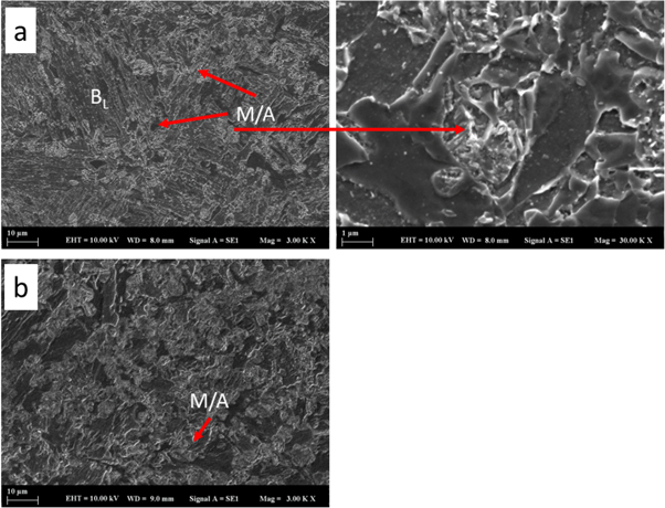
Figure 9. ICR-CGHAZ of W-5 (a) and S-12 (b).
Download figure:
Standard image High-resolution image3.2. Mechanical properties
3.2.1. Hardness
The effect of heat inputs via different techniques (weaving and stringer multi-passes) on HAZs in joining of ultra-high strength steels was discussed above. In order to evaluate the transformations that occurred in these regions in terms of hardness, consecutive hardness measurements from the face, middle, and root regions in weld metal were realized, and these results were interpreted with the help of micrographs of relevant HAZ regions. When hardness graphs for W-5 given in figure 10 are investigated, excessive hardness of CGHAZ near the face of the joint is prominent. Since this region has not been subjected to subsequent heat treatment, which is caused by heat input and transfer by following passes and rapid cooling from critical transformation temperature, these are the reasons why this region was considerably harder than the base metal. While the average hardness of the base metal is 364.2 ± 8.3 HV1, CGHAZ is the hardest region of the joint with 428 ± 8.5 HV1. Hardness has a decreasing trend towards FGHAZ and ICHAZ regions, and SCHAZ has the lowest hardness values for all three measurement lines depicting different layers (i.e., face, middle and root). SCHAZ of the middle layer, tempered with high heat input, has the lowest hardness of 261 HV1. When the strengthening mechanism in steel, which is primarily controlled by resistance to movement of dislocations, and the SCHAZ region subjected to peak temperature high enough (but lower than Ac1) to relax dislocations are both considered, it is revealed that hardness drop is related to a decrease in dislocation density. WM hardness values were recorded as 356.4 ± 7.8, 318.6 ± 9.7, and 319.4 ± 11.3 for face, middle and root, respectively. The hardness of the middle and root regions was approximately 10% lower because of repetitive thermal cycles.

Figure 10. Vickers hardness graph of W-5 joint.
Download figure:
Standard image High-resolution imagePeaks in hardness measurements of S-12 reveal 435 ± 8 HV1 hardness in CGHAZ (figure 11). Hardness presents considerable deviations due to microstructural variations caused by stringer beads (without weaving). Unlike W-5, peaks at the hardness profile correspond to reheated regions in the weld metal. Different from W-5, hardness of 412 ± 21 HV1 at the face in some regions in weld metal nearly reached CGHAZ hardness. Another difference in HAZ sub-regions is that hardness drop is limited because of less heat input than W-5. The lowest hardness measured in SCHAZ is 281 HV1. Lower heat input caused peak temperature to drop in this region, resulting in a limited effect on dislocation density compared to W-5. As a result of regional changes in hardness, weld metal presents inevitable regional and holistic strength variations.

Figure 11. Vickers hardness graph of S-12 joint.
Download figure:
Standard image High-resolution image3.2.2. Impact toughness
Charpy V- impact test results are presented in table 4. Toughness values of 179 ± 9 J and 74 ± 7 J were obtained for HAZs of W-5 and S-12 joints, where non-uniform microstructure and hardness were present, respectively. The location of notch specimens is quite correlated with impact energy results. The most important reason why the W-5 joint, which presents a larger HAZ, has lower toughness values is that location of the notch is less on base metal because of the change in the shape of the weld metal. Both joints fulfill the requirements, which is a minimum of 50 J, for S960QL ultra-high strength steel per EN ISO 10025-6 at −20 °C [32].
Table 4. Charpy impact test results.
| Joint | Test Temperature (°C) | Impact Energy (J) |
|---|---|---|
| W-5 | −20 | 80-81-71-77-63 |
| S-12 | 170-168-189-186-183 |
Fractographs and SEM images related to W-5 HAZ and S-12 HAZ sections are presented in figures 12(a) and (b), respectively. Fracture images characterize fracture initiation zone (a1–b1), crack propagation zone (a2–b2) and final fracture zones (a3–b3). Unlike S-12 impact specimen, where there was around 1.6 mm lateral expansion (17.5%), there was almost no lateral expansion (only ∼0.37 mm or 4%) in W-5 specimen. Quasi-cleavage fracture was observed until final fracture zone (a1–a2). In S-12 specimen, there was no shiny-bright fracture surface and shear area, which is an indicator of toughness, was larger. Compatible with the impact energy values, S-12 specimen had ductile structure with dimples being smaller in fracture initiation and final fracture zones (b1–b3) and larger in crack propagation zone (b2) [47].

Figure 12. Macrographs and SEM images showing fracture surfaces for HAZs of W-5 joint (a) and S-12 joint (b).
Download figure:
Standard image High-resolution image
4. Conclusion
Based on the results obtained, the following conclusions can be drawn on the effect of different heat inputs via the application of weaving and stringer pass techniques in GMAW of S960QL ultra-high strength steel:
- Utilization of the weaving technique reduces the peak temperature at the coarse grain HAZ of the weaving pass (W-5) joint. On the contrary, extended exposure time to a peak temperature and slow cooling time supported PAG growth. Stringer pass (S-12) joint had smaller PAGs due to less exposure time.
- Martensite within the blocks of quite small PAGs yields a splendid balance between strength and toughness in fine-grain HAZs of both joints.
- In the microstructure of inter-critical HAZs of both joints, unchanged islets between a chain of partially transformed austenite, martensite, and some tempered martensite formed by partially nucleated grains along the PAGs can be observed.
- Hardness drop in W-5 joint is attributed to a decrease in dislocation density. Hardness peaks for the S-12 joint are attributed to reheated regions in the weld metal. Contrary to the W-5 joint, hardness drop in HAZ subregions is limited due to less heat input. Hardness of SCHAZ and WM of S-12 joint was 7% and 18% higher compared with W-5 joint, respectively.
- Both joints fulfill the minimum toughness requirement (min. 50 J) at −20 °C per EN ISO 10025-6. However, the S-12 joint presented ~2.5x average impact energy compared with the W-5 joint, which had a larger HAZ. Lateral expansion of impact specimen of S-12 was ~4x higher than that of W-5 specimen.
Acknowledgments
The authors would like to thank Gedik Welding for supporting robotic welding. The authors received financial support for this research from Yildiz Technical University Scientific Research Projects Coordination Unit with Project No: FBA-2018-3225.
Data availability statement
The data that support the findings of this study are available upon reasonable request from the authors.
Statements & declarations
The authors would like to thank Gedik Welding for their support in robotic welding.
Conflict of interest
The authors declare no competing interests.
Funding
The authors received financial support for this research from Yildiz Technical University Scientific Research Projects Coordination Unit with Project No: FBA-2018-3225.
Author contributions
Tolga Mert: supervision, conceptualization, investigation, review, writing, and editing.
Uğur Gürol: experiments, investigation, writing and editing.
Mustafa Tümer: conceptualization, investigation, and writing.