
Abstract
Thermal barrier coating plays a vital role in protecting materials' surfaces from high-temperature environment conditions. This work compares the demeanour of uncoated and air plasma sprayed Cr3C2–25NiCr and NiCrMoNb coated X8CrNiMoVNb16–13 substrates subjected to air oxidation and molten salt (Na2SO4 + 60%V2O5) environment condition at 900 °C for 50 cycles. Coating characteristics have been analyzed through microstructure, thickness, porosity, hardness, and bond strength. SEM, EDS and XRD analysis were used to analyze corrosion's product at the end of the 50th cycle. Coating microstructures showed a uniform laminar structure that is adherent and denser with a coating thickness of 150 ± 20 μm and porosity less than 3.5%. The Microhardness of both the coated substrates were higher than that of the bare substrate. Cr3C2–25NiCr and NiCrMoNb coating bond strength was 38.9 MPa and 42.5 MPa. Thermogravimetric analysis showed the parabolic rate law of oxidation for all the substrates in both environments. In the molten salt environment, all the substrates exhibited higher weight gain compared to the air oxidation environment. In both environmental conditions, the uncoated X8CrNiMoVNb16–13 alloy exhibited higher weight gain than the coated substrates. The formation of Cr2O3, NiO and spinel oxide NiCr2O4 offers good resistance to corrosion to all the substrates in both the environmental condition. However, the presence of Mo and Nb significantly accelerated the corrosion of the substrate, thereby increasing the weight of the NiCrMoNb substrate. It is observed that Cr3C2–25NiCr and NiCrMoNb coating over the X8CrNiMoVNb16–13 substrate significantly protected the substrate against the hot corrosion than the bare alloy exposed to similar environmental conditions.
Export citation and abstract BibTeX RIS

Original content from this work may be used under the terms of the Creative Commons Attribution 4.0 licence. Any further distribution of this work must maintain attribution to the author(s) and the title of the work, journal citation and DOI.
1. Introduction
High-temperature corrosion is a form of accelerated oxidation that occurs at all the engineering components utilized in high-temperature applications in the presence of molten salt [1]. Generally, failure of components due to hot corrosion is common in several engineering fields such as petrochemical, aviation, and power generation industries. However, these failures occur due to contaminations such as vanadates, chlorides and sulphides present in those high-temperature environment conditions. These contaminations form a eutectic mixture around the metal surface at a specific temperature. As a result, porous oxides, as well as non-protective oxide scales, are developed over the surface of the metal. These oxides act as destructive element that breaches the substrate and degrade metals [1].
X8CrNiMoVNb16–13 alloy is precipitation strengthened, austenitic high temperature special steel developed for working at high-temperature application [2]. The alloy exhibits good oxidation resistance and provides good strength at high temperatures. It is generally used in high-temperature applications like gas turbine components such as turbine blades, guide brushes, valve stems in petrochemical industries as pipes and as a heat exchanger in the boiler power plant [2]. However, they are generally affected by high-temperature corrosion induced by molten salt, which degrades the life of the components.
Dedov et al [3] study the corrosion and life assessment behaviour of SA213-TP347HFG, X8CrNiMoNb16–16 austenitic steel. These steels are almost similar to the composition to that of X8CrNiMoVNb16–13 steel. They stated that the materials are subjected to laboratory conditions and an actual power plant environment. They also stated that spallation occurred in both the materials subjected to both the environmental condition. However, it is found that the X8CrNiMoNb16–16 austenitic steel produced less spallation than SA213-TP347HFG steel in actual power plant environment conditions by forming more protective oxides. These protective oxides acted as a barrier in protecting the surface of the materials for the harsh environmental condition by increasing the component's life.
Mahajan and Chhibber [4] explored various steels corrosion behaviour in the power plant at 950 °C under different molten salt environmental conditions. They found that steel that contains high Cr provided good corrosion resistance by forming Cr2O3 protective oxides. The addition of V2O5 and chlorine salts to the Na2SO4 formed a eutectic mixture that contributed to more material corrosion than other mixtures of molten salts. In addition, the formation of Fe2O3 porous oxide helped to enhance the materials' corrosion rate.
Charng-Cheng Tsaur [5] explored the corrosion behaviour of 310 stainless steel coated with NaCl/Na2SO4 mixtures of different compositions (100/0 wt%, 75/25 wt%, 50/50 wt%, 25/75 wt% and 0/100 wt%) exposed to 750 °C. They found that NaCl is the leading corrosion catalyst for weight gain. In addition, the existence of NaCl prevents the formation of protective oxides, leading to the propagation of hot corrosion of 310SS. They also found that the amount of intergranular attack is more prominent as the increase in content of Na2SO4 in the mixture.
Niraj Bala et al [6] investigated the two boiler steels SA-213-T22 and SA 516 alloys coated with Ni-50Cr powder using a cold spray process. The authors stated that both the uncoated boiler steels SA-213-T22 and SA 516 alloys degraded from severe spallation in the form of oxide scales, which may be due to the formation of unprotective Fe2O3 oxide scales. In contrast, both Ni–50Cr coated steels showed lesser weight gains, and the oxide scales spallation until the end of the experiment. They also found that oxides of the coated specimens mainly consisted of Cr and Ni and their spinel's and acted as a protection against the hot corrosion.
It is evident from the above literature that exposure of X8CrNiMoVNb16–13 alloy substrate to a high-temperature environment will significantly decrease the service life of the components. Furthermore, Natesan [7] also stated that hot corrosion plays a significant role in degrading the life of the materials used in applications such as heat exchangers; power generation systems. Therefore, to safeguard the materials from corrosion, it is essential to develop a specific technique that protects the surface of components from a harsh environment. One of the main methods is modifying the material's surface by coating suitable protective coating. This protective coating act as a barrier that prevents the deteriorating life of the materials [8]. In this regard, several coating techniques are available commercially that can be utilized to coat over metallic materials, such as high-velocity oxy-fuel spraying (HVOF) and air plasma spray technique for high-temperature applications [8, 9]. Generally, this coating acts as a barrier against corrosion, thereby increasing the component's life to some extent [10, 11].
In this research work, an air plasma spray process is used to coat the Cr3C2–25NiCr and NiCrMoNb powder on the X8CrNiMoVNb16–13 alloy substrate. Generally, the plasma spray process is preferred because it produces a denser and more robust coating than the other thermal spray techniques such as flame spray and arc spray processes. It also produces a coating with higher strain tolerance, lower oxide content, rapid solidification, higher depositing velocity, good bond strength, etc [12]. The Cr3C2–25NiCr coating is extensively utilized in various engineering applications to safeguard the material surface against corrosion, erosion and wear at high temperatures. It provides good resistance to corrosion and tribological properties at service temperatures. Thus, it improves the component life against an aggressive environment [13]. NiCrMoNb coatings are used for surface protection of components against hot corrosion in both acidic and salt environments. It is generally used to refurbish parts and as a bond coat for ceramic coating [14]. Hence, in this study, Cr3C2–25NiCr and NiCrMoNb coatings were used as protective barrier coating against a high-temperature corrosion environment.
Sreenivasulu and Manikandan [14] studied the corrosion demeanour uncoated and plasma spray-coated (Cr3C2–25NiCr and NiCrMoNb) substrates in air oxidation (AO) and molten salt (MS) environments at 900 °C. They found that uncoated substrates covered with MS exhibited more mass gain as the MS accelerated the corrosion than thermal barrier coated substrates subjected to the same environmental condition. At the initial stage, NiO, Cr2O3, and NiCr2O4 phases act as a protective barrier for these substrates.
Singh et al [15] investigate the corrosion demeanour of various combinations of Cr3C2-NiCr coating on T22 boiler steel substrate exposed to the molten salt environment at 700 °C. They stated that all the substrates (uncoated and coated) exposed to a molten salt environment exhibited weight gain because of the Fe2O3 porous oxide scale formed on the surface. In addition, they found that 10Cr3C2–90NiCr and 20Cr3C2–80NiCr coatings exhibited good corrosion resistance compared to 35Cr3C2–65NiCr and 100NiCr. They concluded that the development of a layer of chromium carbide scale on the surface of the coated substrate protected the substrate from corrosion.
Sundararajan et al [16] explored the corrosion demeanour of HVOF and plasma sprayed Ni-20Cr coated 9Cr – 1Mo steel substrates at 600 °C to 750 °C. They stated that the coating protected the substrate from a harsh environment irrespective of the temperature. They also found that the development of the Cr2O3 protective oxide layer played the active role of protecting the substrate surface against corrosion at high temperatures.
Gosh et al [17] studied the effect of plasma-sprayed Cr3C2-NiCr coated 2.25Cr – 1Mo steel substrate on the air oxidation environment at 523 °C for 72 h. They found that Cr3C2-NiCr coating provided significant corrosion resistance to 2.25Cr–1Mo substrate at air oxidation than the uncoated substrates. The increase in weight gain is caused by the migration of prominent element Fe towards O. The corrosion resistance is offered by the formation of Cr2O3 oxide that acted as a diffusion barrier against the O to the substrate.
Rakesh Bhatia et al [18] investigated the effects of high-velocity oxy-fuel sprayed 75% Cr3C2–25% (Ni-20Cr) coated T-91 boiler tube steel against hot corrosion at various temperatures 550, 700 and 850 °C. The coating deposited over the surface of the substrate was uniform with less than 2% porosity. Furthermore, they found that coated substrates showed less weight gain than the uncoated substrate, irrespective of the temperature. Hence they have concluded that coating of Cr3C2–25% (Ni-20Cr) over T-91 boiler tube steel substrate effectively protects the surface of the substrates against hot corrosion.
Kaur et al [19] studied the high-temperature corrosion behaviour of detonation gun sprayed coated Cr3C2–NiCr SAE–213–T22 and SAE–347H boiler steels exposed to Na2SO4–82%Fe2(SO4)3 at 700 °C. They found intense spalling in SAE–213–T22 steel, whereas marginal spallation was observed in SAE– 347H steel. In contrast, Cr3C2–NiCr coated SAE–213–T22 steel and SAE– 347H steel showed no spallation of oxide scales. Hence, they concluded that coating successfully resisted the substrate against hot corrosion in the molten salt environment.
Sreenivasulu and Manikandan [20] studied the effect of Cr3C2–25NiCr, and NiCrMoNb coating on alloy 80 substrate subjected to both AO and MS environment at 900 °C. The authors found intense spallation in uncoated alloy 80A substrates exposed to AO and MS environments. They also inferred that coating of Cr3C2–25NiCr and NiCrMoNb powder over the surface of the alloy 80A substrate help in protecting the substrates against the severe high-temperature environment. Furthermore, the presence of protective oxides such as NiO, Cr2O3 and NiCr2O4, NiMoO4 acted as a barrier in protecting the substrate against high-temperature corrosion.
Thus, for the above literature, it is deduced that deposition of thermal spray coatings over the surface of the substrate protect the substrates from the various high-temperature aggressive environment. Hence, the objective of this work is to investigate the effectiveness of the coating and compare the performance of uncoated and plasma sprayed Cr3C2–25NiCr, and NiCrMoNb coated X8CrNiMoVNb16–13 alloy subject to AO and MS (Na2SO4 + 60%V2O5) environment condition at 900 °C. This study will be highly beneficial for various industries such as power plant, petrochemical and aerospace industries for the selection of appreciate substrate and coating materials and to solve the materials degradation problem encountered during their operations.
2. Materials and methodology
2.1. The substrate material
X8CrNiMoVNb16–13 alloy studied in this work was acquired in 64 mm diameter rod diameter from M/S Stooss, Switzerland. Firstly, the band saw machine sectioned the procured material to 64 mm × 7 mm thick disc. Secondly, it was machined using a wire electric discharge machining machine (WEDM) into a rectangular piece of dimension 20 × 15 × 7 mm thickness. These substrates are then polished on all sides to remove any irregularities from the surface of the substrates. The polished substrates were then coated with Cr3C2–25NiCr (company name: Oerlikon Metco and powder grade: Woka – 7202) and NiCrMoNb (company name: H.C. Starck and powder grade: Amperit 380.088) coating powders using an air plasma spray process. Finally, substrates were polished to maintain uniform surface roughness on all samples. Their compositions are given in table 1.
Table 1. Elemental composition (Wt%) of substrate and coating powders.
| Substrate/Coating powders | Chemical composition (Wt%) | ||||||||
|---|---|---|---|---|---|---|---|---|---|
| Ni | Cr | Fe | Mn | Si | V | Mo | Nb | Other | |
| X8CrNiMoVNb16–13 Alloy | 12.5 | 15.5 | Bal. | 0.9 | 0.32 | 0.67 | 1.19 | 0.84 | 0.017(C), 0.010(S), 0.012(P) |
| Cr3C2–25NiCr | 20.6 | Bal. | 0.15 | — | — | — | — | — | 9.6 (C) |
| NiCrMoNb | Bal | 22.1 | 0.1 | — | — | — | 9.0 | 3.4 | 0.2 (Co) |
2.2. Coating and hot corrosion test
This work compares the demeanour of uncoated substrates and plasma sprayed Cr3C2–25NiCr, and NiCrMoNb coated X8CrNiMoVNb16–13 alloy substrates in AO and MS (Na2SO4 + 60%V2O5) environments at 900 °C for 50 cyclic conditions. The coating was done using air plasma spray system M/s AMT AG, Switzerland (Gun type: F4MB gun and Model: MP200), operating with hydrogen and argon as input gas. The coating process parameters used for coating Cr3C2–25NiCr and NiCrMoNb powder on the substrate are illustrated in table 2.
Table 2. Air plasma spray process parameter utilized for coating Cr3C2–25NiCr and NiCrMoNb over X8CrNiMoVNb16–13 alloy substrate.
| Process parameters | Cr3C2–25NiCr powder | NiCrMoNb powder |
|---|---|---|
| Argon Flow (LPM) Pressure (bar) | 55 & 5 | 43 & 5 |
| Hydrogen (ATF) Flow (LPM) & Pressure (bar) | 12 & 5 | 9. & 5 |
| Argon (Carrier) Flow (LPM) & pressure (Bar) | 3.2 & 5 | 3.2 & 5 |
| Powder feed rate (g min−1) | 40 | 30 |
| Current (Amps) | 600 | 550 |
| Voltage (V) | 80 | 77 |
| Coating angle | 90° | 90° |
| Stand-Off distance (mm) | 130 | 120 |
The size and shape of the Cr3C2–25NiCr powder particle are 45/15 μm and spherical shape, manufactured through agglomeration and sintering [13]. NiCrMoNb powder particle size is 53/20 μm, and they are spherical and manufactured through a gaseous atomization process [14]. The coating was conducted on all sides of X8CrNiMoVNb16–13 alloy substrates with an average thickness range of 150 ± 20 μm.
The plasma-sprayed coated and uncoated X8CrNiMoVNb16–13 alloy substrates are subjected to a hot corrosion test. Both coated (Cr3C2–25NiCr and NiCrMoNb (2 samples for each coating)) and uncoated X8CrNiMoVNb16–13 alloy substrates (2 samples) were subjected to AO and MS (Na2SO4 + 60%V2O5) environmental conditions. As such, before introducing the substrates to the furnace, both Cr3C2–25NiCr and NiCrMoNb coated X8CrNiMoVNb16–13 alloy substrates are coated with Na2SO4 + 60%V2O5 molten salt environment condition. Initially, the salts are blended with distilled water and applied all over the surfaces of the substrates (both Cr3C2–25NiCr and NiCrMoNb) at a range of 3 to 5 mg cm−2. They are then exposed to 200 °C in the box furnace for 3 h to remove the moisture content and adhesion of MS over the substrate surface. Next, these MS coated substrates with their respective boat are weighed using an electrical balance (Metler Toledo), which has an accuracy of ± 0.01 mg before starting to hot corrosion study. These weighted MS coated substrates and AO substrates are then exposed to cyclic hot corrosion study in AO and MS environments at 900 °C inside the tubular furnace separately. The hot corrosion test was conducted for 50 cycles, i.e., heating at 900 °C for 1 h and then cooling at sand bath for 20 min to attain room temperature (which is one cycle), and this process is repeated for 50 cycles. During this process, the weighing of all the substrates was carried out. The average of the two samples (both uncoated and coated) were considered for the discussion.
2.3. Metallurgical characterization of coatings
The macroscale examination was conducted to study the morphology of the substrates exposed to hot corrosion tests at the end of every 5th cycle up to the final 50th cycle. Scanning electron microscope (SEM) (Make: Carel Zeiss; Model: EVO 18)/electron dispersive spectroscopy (EDS) (Make: Oxford instrument X-act) was conducted on the surface of all the substrates to analyze the structural morphology and elements of corrosion product. In addition, XRD analysis was conducted on all the substrates exposed to the hot corrosion test to recognize the corrosion product, which contributes to the weight gain of the substrate.
2.4. Coating characterization
The cross-sectional area assessed the hardness, porosity, thickness, and bond strength of the coatings (Cr3C2–25NiCr and NiCrMoNb). The coated substrates were sectioned using a slow speed cutting machine (Model no.: LSS003; Make: Chennai Metco). Microhardness test (software: Hardcom Hv and Make: MATSUZAWA) was conducted to assess the hardness of the coatings. The hardness measuring was conducted from the substrate to the coating area through the substrate/coating interface. Around seven random indentations were taken on the substrate, followed by six/seven indentations in the coating. ASTM E84 was utilized to assess the hardness of the coatings. The coating porosity was assessed using image analysis software using the ASTM B276 standard [21]. The porosity assessment is carried out at 7 to 8 different places for each coating sample with 20 μm magnification and an average of those used in the study. The coatings thickness was assessed through an optical microscope. The coated cylindrical sample diameter 25.4 mm × 38.1 mm was utilized to measure the coating bond strength through ASTM C633 at Metallizing Equipment Ltd, India. HTK Ultra bond epoxy was used to glue the surface of the coated substrate to the uncoated substrate. Instron universal testing machine (Model: 5969) was utilized to conduct the bond strength test on coated and uncoated cylinders coupling specimen.
3. Results
3.1. Evaluation of coating porosity and thickness
Figures 1(a) and (b) illustrate the cross-sectional micrographs of Cr3C2–25NiCr and NiCrMoNb coated X8CrNiMoVNb16–13 alloy substrates. The micrograph showed the existence of inclusion and porosity in the coating. The coating porosity was evaluated using a micrograph through image analysis software. The average porosity on the Cr3C2–25NiCr coating is found to be 3.19%, and for NiCrMoNb coating is found to be 2.57%. The average thickness of Cr3C2–25NiCr and NiCrMoNb coating is identified as 170 and 150 μm, respectively. Figure 2 shows the surface morphology of all the substrates.

Figure 1. Cross sectional micrograph of X8NiCrMoVNb16–13 substrate coated with (a) Cr3C2–25NiCr coating and (b) NiCrMoNb coating.
Download figure:
Standard image High-resolution image
Figure 2. 50th cycle surface morphology of X8NiCrMoVNb16–13 substrate subjected to AO and MS environment (a) X8NiCrMoVNb16–13 - AO; (b) X8NiCrMoVNb16–13 – MS; (C) Cr3C2–25NiCr – AO; (d) Cr3C2–25NiCr – MS; (e) NiCrMoNb – AO and (f) NiCrMoNb – MS.
Download figure:
Standard image High-resolution image3.2. Hardness measurement of the coatings and substrate
Figure 3 illustrates the hardness profile taken from X8CrNiMoVNb16–13 alloy substrate to Cr3C2–25NiCr and NiCrMoNb coating. The average Microhardness of uncoated X8CrNiMoVNb16–13 alloy substrate is 180 ± 10 Hv0.3 and for Cr3C2–25NiCr and NiCrMoNb coated substrates, it is identified as 791 ± 30 Hv0.3 and 311 ± 10 Hv0.3, respectively.

Figure 3. Microhardness profile of X8NiCrMoVNb16–13 substrate coated with Cr3C2–25NiCr and NiCrMoNb coating.
Download figure:
Standard image High-resolution image3.3. Evaluation of coating bond strength
Figure 4 illustrates that the cohesion failure of the coating happened during the bond strength test. The bond strength of Cr3C2–25NiCr and NiCrMoNb coating (2 samples each) was 38.9 MPa and 42.5 MPa, respectively. From figure 4, it is found that the cohesion mode of failure has occurred in the present study. The cohesive failure results from fracture on the layer of Cr3C2–25NiCr and NiCrMoNb coated surface before the adhesion failure.

Figure 4. Fractured surface of coated X8NiCrMoVNb16–13 substrate.
Download figure:
Standard image High-resolution image3.4. Corrosion kinetics
Figure 5 shows the change in weight of X8CrNiMoVNb16–13 alloy substrate in AO and MS environments with respect to time. It is identified that (figure 5), all the substrates subjected to the test increased in weight gain, which is due to the corrosion induced by the high-temperature environment. However, MS coated substrates showed more weight gain than their respective AO substrate because of the initiation and acceleration of corrosion induced by the MS environment.

Figure 5. Weight gain versus number of cycles graph of all the X8NiCrMoVNb16–13 substrate subjected to AO and MS environment.
Download figure:
Standard image High-resolution imageIt is observed that, during the first 8 cycles (1st to 8th cycle), the exponential increase in weight was found in all the substrates increases exponentially, which denotes the rapid oxidation formation on the surface of all the substrates such as oxides formed through Ni and Cr and other elements. After the initial cycles, the weight gain of substrates started to rise gradually. It is also observed (figure 5) that Cr3C2–25NiCr and NiCrMoNb coated X8CrNiMoVNb16–13 alloy substrates performed better than uncoated substrates in both AO and MS environments. Overall, more weight gain was noted in MS coated substrates than its respective AO environment substrates. This phenomenon denotes that the MS environment initiated the corrosion and provided the pathway for more oxidation, which resulted in harmful oxides formed through elements such as Mo, V, Na, Fe, S, and other elements. Figure 6 represents the weight gain square versus the number of cycles of substrates subjected to AO and MS environments at 900 °C.

Figure 6. Weight gain square versus number of cycles graph of all the X8NiCrMoVNb16–13 substrate subjected to AO and MS environment.
Download figure:
Standard image High-resolution imageUsing a linear least square equation (1), the parabolic rate (Kp) was determined

Where t represents time (s), ΔW changes in substrate weight, and A represents the sample's surface area. Table 3 shows the value of Kp (g2 cm−4 s−1), total weight gain (mg cm−2), total weight gain square (mg cm−2)2 of both coated and uncoated substrates (Cr3C2–25NiCr and NiCrMoNb coated X8CrNiMoVNb16–13 alloy substrates) exposed to AO and MS environments.
Table 3. Parabolic rate law constant of all the substrates subjected AO and MS environmental condition at 900 °C.
| Substrates | Environment | Total Weight Gain (mg cm−2) | Total Weight Gain Square (mg cm−2)2 | Parabolic Rate Law Constant (Kp) (g2/cm4/s1) |
|---|---|---|---|---|
| Uncoated X8CrNiMoVNb 16–13 | Air Oxidation | 5.76 | 33.18 | 1.83 × 10⁻⁴ |
| Molten salt | 10.89 | 118.58 | 6.54 × 10⁻⁴ | |
| Cr3C2–25NiCr coated X8CrNiMoVNb 16–13 | Air Oxidation | 5.11 | 2.14 | 1.44 × 10⁻⁴ |
| Molten salt | 7.44 | 55.40 | 3.04 × 10⁻⁴ | |
| NiCrMoNb coated X8CrNiMoVNb 16–13 | Air Oxidation | 4.22 | 17.78 | 9.83 × 10⁻⁵ |
| Molten salt | 8.93 | 79.70 | 4.38 × 10⁻⁴ |
It is observed from figures 5 and 6 that all the substrates followed the parabolic path. It is noted that during specific cycles, there is a sharp increase in weight gain, which is because of the accelerated formation of oxides (oxide formed through elements such as Ni, Cr, V, and other protective elements) in both environments. This phenomenon is identified during the 9th and 10th cycles because of the evaporation of volatile compounds and the formation of protective oxides. There was also some abrupt decrease in weight gain phenomenon observed in some cycles due to evaporation of Na, Mo, Fe, S, and other volatile oxides from the surface and sub-surface layer of the substrates at 900 °C [14]. During 24th to 50th cycle, there is a steady increase in the weight observed, and also a gradual increase in the development of protective oxide layer on the substrate surface/coated surface (oxide formed through elements Ni, Cr, and other elements) that arrest/interrupt the rapid oxidation from the coated/substrate surface to the sub-surface layers of the substrates.
3.5. Surface analysis by SEM/EDS analysis
The SEM/EDS analysis is conducted on the surface of uncoated and Cr3C2–25NiCr, and NiCrMoNb coated X8CrNiMoVNb16–13 alloy substrates at a selected point to determine the product of corrosion or protective oxides as a result of high-temperature corrosion correlated with AO and MS environment at 900 °C. Figure 7 shows the 50th cycle SEM/EDS study on the surface of the uncoated and Cr3C2–25NiCr and NiCrMoNb coated X8CrNiMoVNb16–13 alloy substrates exposed to AO and MS environments.

Download figure:
Standard image High-resolution image
Figure 7. 50th cycle SEM-EDS analysis of X8NiCrMoVNb16–13 substrate subjected to AO and MS environment (a) X8NiCrMoVNb16–13 - AO ; (b) X8NiCrMoVNb16–13 – MS; (C) Cr3C2–25NiCr – AO; (d) Cr3C2–25NiCr – MS; (e) NiCrMoNb – AO and (f) NiCrMoNb – MS.
Download figure:
Standard image High-resolution imageIn uncoated X8CrNiMoVNb16–13 alloy substrate (figure 7(a)) exposed to the AO environment, the prominent elements are Fe, Cr, O, Mn, Nb and Mo, and some minor such as Si, V, and Ni is found on the surface of the substrate. In uncoated X8CrNiMoVNb16–13 alloy substrate (figure 7(b)) exposed to the MS environment, the prominent elements are Fe, Cr, O, Ni, and V, and some minor such as Mo, Mn, S, Si and Na is found. In Cr3C2–25NiCr coated substrate (figure 7(c)) exposed to AO environment, the prominent element is found to be Ni, Cr, O, Mn and minor element Fe is identified. In the case of Cr3C2–25NiCr coated substrate (figure 7(d)) exposed to MS environment, the prominent element is found to be Ni, Cr, O, Fe, Mo, V and minor elements Mn, Na and Si are identified. However, in NiCrMoNb coated substrate (figure 7(e)) exposed to AO environment, the prominent element is found to be Ni, Cr, O, Mo, Nb and minor element Fe and Mn are identified. In the case of NiCrMoNb coated substrate (figure 7(f)) exposed to MS environment, the prominent element is found to Ni, Cr, O, Fe, Mo, Nb and minor elements S, Mn, Na are found.
3.6. XRD analysis
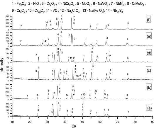
XRD analysis is carried out at the surface of uncoated and Cr3C2–25NiCr, and NiCrMoNb coated X8CrNiMoVNb16–13 alloy substrates to determine the non-protective and protective oxide phases, which are formed as a result of high-temperature corrosion correlated with AO and MS environments. Figure 8 shows the XRD analysis conducted at the surface of the uncoated and Cr3C2–25NiCr and NiCrMoNb coated X8CrNiMoVNb16–13 alloy substrates exposed to AO and MS environments, and the results are consolidated in table 4.
Figure 8. 50th cycle XRD analysis of X8NiCrMoVNb16–13 substrate subjected to AO and MS environment (a) X8NiCrMoVNb16–13 - AO; (b) X8NiCrMoVNb16–13 – MS; (C) Cr3C2–25NiCr – AO; (d) Cr3C2–25NiCr – MS; (e) NiCrMoNb – AO and (f) NiCrMoNb – MS.
Download figure:
Standard image High-resolution image
Table 4. Corrosion product of uncoated and Cr3C2–25NiCr and NiCrMoNb coated X8CrNiMoVNb16–13 alloy substrate subjected AO and MS environmental condition at 900 °C.
| Substrates | Environment | Corrosion products |
|---|---|---|
| Uncoated X8CrNiMoVNb 16–13 | Air Oxidation | Cr2O3, NiO, Fe2O3, NiCr2O4, MoO3 and NbNi3 |
| Molten salt | Cr2O3, NiO, Fe2O3, NiCr2O4, MoO3, NbNi3, NaVO3 and Na(FeO2) | |
| Cr3C2–25NiCr coated X8CrNiMoVNb 16–13 | Air Oxidation | Cr2O3, NiO, Fe2O3, NiCr2O4,, Cr3C2, and Cr23C6 |
| Molten salt | Cr2O3, NiO, Fe2O3, NiCr2O4,, Cr3C2, Cr23C6, VC and Na2CrO4 | |
| NiCrMoNb coated X8CrNiMoVNb 16–13 | Air Oxidation | Cr2O3, NiO, Fe2O3, NiCr2O4, MoO3, NbNi3, Nb21S8 |
| Molten salt | Cr2O3, NiO, Fe2O3, NiCr2O4, MoO3, NbNi3, NaVO3, Nb21S8, CrMoO3 and VC |
4. Discussion
This work deals with the study on the behaviour of uncoated and Cr3C2–25NiCr and NiCrMoNb coated X8CrNiMoVNb16–13 alloy substrate subjected to AO and MS environmental conditions at 900 °C. The micrograph (figure 1) illustrated the existence of inclusion and porosity in the coatings. Wigren and Tang [22] stated that the coating microstructure consists of the oxides, pores, and some unmelted particles near the substrate/coating interface. They also stated that the coating was deposited on the substrates in a layer by layer method. The formation of oxides is due to the oxidation process that occurs when powder particles strike the substrate's surface [23]. Furthermore, the coating thickness precludes the materials from wear and corrosion at high temperatures [9, 24]. Hence in this work, Cr3C2–25NiCr and NiCrMoNb were coated on the X8CrNiMoVNb16–13 substrates with the thickness of 170 and 150 μm.
The amount of coating porosity is proportional to the corrosion resistance offered by the substrates. Therefore, denser coating always offers better corrosion resistance than porous coating because it arrests the infiltration of harmful oxide to the substrate, thereby protecting it from oxidation. Generally, air plasma spray coating offers porosity ranges from 5 to 10 % [23]. In this study, the porosity on the Cr3C2–25NiCr coating is 3.19 %, and for NiCrMoNb coating is found to be 2.57 %, which confirms that denser coating was achieved.
Another important property for characterizing the coating is Microhardness. The average Microhardness of Cr3C2–25NiCr and NiCrMoNb coated X8CrNiMoVNb16–13substrates are 791 ± 30 Hv0.3 and 311 ± 10 Hv0.3, respectively. The higher hardness value found in the Cr3C2–25NiCr coating is because of brittle Cr3C2 carbides in the NiCr matrix. It is also observed that both the coating offers more hardness (figure 2) than the substrate due to the high surface area and kinetic energy achieved by the powder particle [25, 26].
Figure 1 illustrates the micrograph of uncoated and Cr3C2–25NiCr and NiCrMoNb coated X8NiCrMoVNb16–13 substrate exposed to AO and MS environment at 900 °C. All the substrates exposed to hot corrosion tests underwent corrosion irrespective of the difference in the coating and the environment. Notably, substrates exposed to the MS environment exhibited more corrosion due to the initiation and acceleration of corrosion induced by the MS (Na2SO4 + 60%V2O5). Figures 5 and 6 show the results of the change in weight versus the number of cycles and cumulative weight gain square versus the number of cycles of all substrates exposed to AO and MS environment at 900 °C. It is noted that, during the first few cycles (1st to 8th cycle), the weight gain of all the substrates increases exponentially. This phenomenon is caused by the rapid oxidation at the surface substrate, such as Cr2O3, NiO, and other oxide formed through various coating elements and substrates [27]. It is also observed that during the 12th and 15th cycles, a sudden increase in the weight gain was observed in uncoated substrate exposed to an MS environment. This phenomenon is due to the simultaneous formation and evaporation of volatile oxide (oxides formed through elements such as Fe and Na) and the formation of protective oxides (oxides formed through elements such as Cr, Ni, and other elements). After the 22nd cycle, all substrates' weight gain increased gradually up to the 50th cycle. This is due to the gradual increase in protective oxide (oxide formed through elements such as Cr, Ni, and other elements) after the evaporation of volatile oxides in the previous cycle. As these protective oxide increases on the substrate surface, it gradually decreases the diffusion of harmful oxide to the bare X8NiCrMoVNb16–13 substrates. This occurrence decreased the substrate's rapid oxidation process, leading to steady-state oxidation until the end of the 50th cycle [28].
Performance/resistance uncoated and Cr3C2–25NiCr and NiCrMoNb coated X8NiCrMoVNb16–13 substrate exposed to AO environment at 900 °C is arranged as follows NiCrMoNb coated substrate > Cr3C2–25NiCr coated substrate > X8NiCrMoVNb16–13 substrate
Uncoated X8NiCrMoVNb16–13 alloy substrate showed significantly less corrosion resistance than the coated substrate because of the formation of more harmful Fe2O3 and MoO3 oxides on the surface of the substrate. These oxides tend to spall from the substrate's surface and provide a pathway for the diffusion of oxides to the sub-surface layer of the substrate, thereby increasing the weight gain of the substrate.
Cr3C2–25NiCr coated substrate showed more weight gain than NiCrMoNb substrate because of the formation of Cr3C2 and Cr23C6 carbide phase on the surface of the substrate which offers less resistance to corrosion to the substrates. This phenomenon is due to the decomposition of the Cr3C2 and Cr23C6 phase that reacts with O2 to form Cr2O3 with CO/CO2 gases liberation. The liberation of CO/CO2 gases and the thermal expansion between the oxide scale and coating caused severe coating spallation from the substrate [29]. Lai et al [30] also stated that exposure of Cr3C2–25NiCr coating to air oxidation environment resulted in severe spallation, and it is due to the stress-induced between the coating and oxide. On the other hand, NiCrMoNb substrate exhibited more corrosion resistance than other substrates in the AO environment because of the formation of more protective oxide Cr2O3, NiO and spinel oxide NiCr2O4 on the surface of the substrate that prevented the internal diffusion of O2 to the bare substrate, which resulted in less weight gain.
The XRD analysis was done to determine the corrosion product at the surface of all the substrates after exposure to AO and MS environment at 900 °C. Figure 8 illustrates the corrosion of uncoated and coated substrate after exposure to the AO and MS environment at 900 °C. The following compounds were identified after the 50th cycle, namely, Ni containing compounds: NiCr2O4 and NiO; Cr- containing compounds: Cr2O3, CrMoO3, Cr3C2, and Cr23C6; Fe containing compound - Fe2O3; Nb containing compound – NbNi3, Nb21S8; Mn containing compound – MnO2. However, XRD analysis has its limitation, i.e., it cannot identify the compounds when vol% of the compounds are less (>5%) [31]. So, apart from the above compounds, compounds such as Ni3V2O8, Na2CrO4, Na2Cr2O7, CrVO4, Cr3S4, FeS and versus might also form, as some traces of Fe, S and V elements are observed in figure 7 [31, 32].
In all the substrates exposed to the hot corrosion test, the EDS analysis's prominent elements are O, Ni, and Cr elements. During the initial stage (1st to 8th cycles), the coating and molten salt elements produce the following reaction at high temperatures. In uncoated substrate, Fe is a prominent element and reacts with O2 to form non-protective Fe2O3 oxide. The formation of NiO, Cr2O3 oxide occurs at approximately 400 °C and between 500 °C to 600 °C.


The rapid weight gain at initial cycles in an MS environment may be because of the development of NaVO3 oxide (melting point 610 °C) [23]. This NaVO3 oxide is formed by reacting Na2SO4 and V2O5 (MS) at 900 °C.


NaVO3 oxide acts as a catalyst and an oxygen carrier, resulting in the oxidation of the substrate to form the protective oxides at the initial cycles [33].
The development of these NiO and Cr2O3 oxides constrains the interior diffusion of oxygen to the bare X8NiCrMoVNb16–13 substrate. These oxides are selectively formed during the initial stage, and it grows steadily in the following cycles to form a steady state of oxidation at the later cycles [24]. High Cr wt% observed in the EDS of all the substrates is due to the higher affinity of Cr with O2 to form Cr2O3 oxides, which arrest the further oxygen potential and promotes the growth of NiO [34]. Choi et al [33] also stated similar findings in their studies. In addition, they found that the development of binary oxides, some ternary oxide such as NiCr2O4 are also formed on the intermediate stages of hot corrosion.

The development of spinel NiCr2O4 oxide on the surface of the substrates increases the oxidation resistance, as these oxides have a smaller diffusion coefficient for cations and anions than the patent oxides. Simultaneously, VO3 - in equation (5) form V2O5, and also some V2O5 from the MS reacts with protective NiO and Cr2O3 oxides to form Ni3V2O8 and CrVO4 oxides, respectively [31]. Porcayo-Calderon et al [35] stated that even at different temperatures (700 °C, 800 °C, and 900 °C), Ni element in the surface form Ni oxide layer, which is rich in Ni, V and O content and the same had been reported by other researchers [31]. These Ni layers are corroded by vanadium salt, but this corroded product acts as a barrier and prevents the infiltration of corrosion agents to the substrate.

V2O5 reacts with Cr2O3 to form CrVO4 oxide, which accelerator corrosion, thereby increasing the corrosion at the surface of the substrates [33].

The Na+ ions from equations (5) and (6) react with O to form Na2O. It then reacts with the protective oxide Cr2O3 to form Na2CrO4 and Na2Cr2O7 oxides, evaporating as a volatile oxide [31]. These Na+ ions also react with Fe and O to form Na(FeO2).


The evaporation of Na2CrO4 and Na2Cr2O7 oxides at 900 °C leads to the development of pit or cavity on the surface of the protective Cr2O3 layer, through which interior diffusion of oxygen through the coating takes place, which then reacts with the substrate Fe, Mn elements form Fe2O3, and MnO2 oxides. The Mn ion existence as a white spot (figure 1) is observed in the top surface of all the substrates oxide layer, and it is identified as MnO2 oxides through XRD analysis. Sidhu et al [28] observed a similar phenomenon in their hot corrosion study on Cr3C2–25NiCr and Ni-20Cr coated of Ni-based superalloy substrates. They also stated that the Mn diffuses from the substrate to the top surface layer of the oxide scales.
Further, SO4 ions from equation (6) react to form SO2 in equation (12). These SO2 reacts with protective Cr2O3 oxide to form Cr3S4 sulfide [31]. SO2 ions react with Fe, Nb, Cr and V to form FeS, Nb21S8 and versus sulfides. These sulfides are the corrosive agent that also contributes to the weight gain of substrates, and the presence of these phases implies the sulfidation process.


Performance/resistance uncoated and Cr3C2–25NiCr and NiCrMoNb coated X8NiCrMoVNb16–13 substrate exposed to MS environment at 900 °C is arranged as follows Cr3C2–25NiCr coated substrate > NiCrMoNb coated substrate > X8NiCrMoVNb16–13 substrate.
Uncoated X8NiCrMoVNb16–13 alloy substrate showed much less corrosion resistance than the coated substrate because of the formation and spallation of Fe2O3 and MoO3 oxides on the surface of the substrate. In addition, evaporation of MoO3, Na2CrO4 and Na2Cr2O7 oxides from the substrates contributed to more oxidation on the substrate, and NiO, NiCr2O4 and Cr2O3 oxides offer corrosion resistance.
Cr3C2–25NiCr coated substrate showed less weight gain than NiCrMoNb substrate in the same environmental condition due to NiO, NiCr2O4 and Cr2O3 oxides on the surface of the coated substrate. These oxides act as a barrier by prevention inward diffusion of oxidation. Sidhu et al [32] explored the hot corrosion behaviour of HVOF Cr3C2-NiCr coated substrate open to MS environment. The Cr3C2–25NiCr coating consists of more Cr wt % in its chemical composition, which adversely affects the hot corrosion by developing more Cr2O3 oxides that contribute to corrosion resistance, and simultaneous formation of vanadium carbide reduces V2O5 formation in molten salt. It is perceived from figure 4(d) that significantly less spallation is achieved in Cr3C2–25NiCr coated substrate compared to Cr3C2–25NiCr coated substrate exposed to AO environment. This phenomenon is due to less internal stress induced by the thin non-protective oxide formation, leading to less substrate weight gain.
NiCrMoNb coated substrate showed more weight gain compared to Cr3C2–25NiCr substrate in the MS environment. The Cr2O3, NiO, NiCr2O4 oxide provides good resistance to corrosion. However, simultaneous formation of Mo element in EDS analysis (figure 7(f)) produced more volatile oxides such as MoO3, CrMoO3 oxides and Nb21S8 sulphide compound compared to Cr3C2–25NiCr substrates, which significantly accelerated the corrosion of the substrate, thereby increasing the weight of the substrate. Mannava et al [31] found a similar view in their study. They stated that the presence of volatile CrMoO3 oxide significantly accelerated the corrosion of the substrate along with the sulphidation process, thereby increasing the weight gain of the substrate.
5. Conclusions
Exposure of metallic components to a high-temperature environment deteriorates the components' service life. X8NiCrMoVNb16–13 alloy is austenitic high-temperature steel developed for working at high-temperature applications such as gas turbine components, heat exchangers in boiler power plants, and pipes in petrochemical industries. To protect the X8NiCrMoVNb16–13 alloy against the high-temperature environment, they were coated with Cr3C2–25NiCr and NiCrMoNb powder. The coated and uncoated substrates were subjected to AO and MS environment for 50 cyclic oxidations at 900 °C, and their performance as discussed below.
- 1.Cr3C2–25NiCr and NiCrMoNb powders were successfully deposited using an air plasma spray method on the surface of the X8NiCrMoVNb16–13 substrate with porosity less than 3.5% and with the bone strength of 38.9 MPa and 42.5 MPa, respectively.
- 2.The average Microhardness of uncoated X8CrNiMoVNb16–13 alloy substrate is 180 ± 10 Hv0.3 and for Cr3C2–25NiCr and NiCrMoNb coated substrates, it is identified as 791 ± 30 Hv0.3 and 311 ± 10 Hv0.3, respectively.
- 3.Thermogravimetric analysis showed that both uncoated X8CrNiMoVNb16–13 substrate and Cr3C2–25NiCr and NiCrMoNb coated substrates followed the parabolic rate law of oxidation.
- 4.Weight gain is observed in all substrates exposed to an AO and MS environment. Na2SO4 + 60%V2O5 initiated and accelerated the corrosion of the substrate at 900 °C.
- 5.The formation of Cr2O3, NiO, NiCr2O4 oxides provides good resistance to corrosion to all substrates subjected to AO and MS environment at 900 °C.
- 6.NiCrMoNb coated substrate showed more weight gain compared to Cr3C2–25NiCr substrate in the MS environment. In addition, the Mo element contributed to the formation of volatile MoO3, CrMoO3 oxides and Nb21S8 compound formation increased the weight gain of the substrate.
- 7.Cr3C2–25NiCr coating performed better in the MS environment, and NiCrMoNb performed well in the AO environment.
Acknowledgments
Authors thank the Vellore Institute of Technology, Vellore for their support in publishing this research work.
Data availability statement
All data that support the findings of this study are included within the article (and any supplementary files).