


Abstract
In this work, we provide the first 2D spatially resolved description of radiative detachment in MAST-U Super-X L-mode divertor plasmas. The Super-X magnetic configuration was designed to achieve reduced heat- and particle loads at the divertor target compared to conventional exhaust solutions. We use filtered camera imaging to reconstruct 2D emissivity profiles in the poloidal plane for multiple atomic and molecular emission lines and bands. A set of deuterium fuelling scans is discussed that, together, span attached to deeply detached divertor states observed in MAST-U. Emissivity profiles facilitate separate analysis of locked-mode induced split branches of the scrape-off layer. Molecular deuterium Fulcher band emission front tracking reveals that the deuterium electron-impact ionisation front, for which it serves a proxy, detaches at different upstream electron densities in the split branches. Upon detachment of this ionisation front, Balmer emission attributed to molecular activated recombination appears near-target. We report a simultaneous radial broadening of the emission leg, consistent with previous SOLPS-ITER modelling. With increased fuelling this emission region detaches, implying electron temperatures below  eV. In this phase, 2D Balmer line ratio reconstruction indicates an onset of volumetric direct electron-ion recombination near-target. At the highest fuelling rates this emission region moves off-target, suggesting a drop in near-wall electron density accompanying the low temperatures.
Export citation and abstract BibTeX RIS

Original content from this work may be used under the terms of the Creative Commons Attribution 4.0 license. Any further distribution of this work must maintain attribution to the author(s) and the title of the work, journal citation and DOI.
1. Introduction
The design space of fusion reactor exhaust is constrained by the required compatibility with a high-performance core plasma and engineering limits on the plasma-facing component (PFC) heat load [1]. Key to strategies envisioned for commercial-scale power plants is operation in the so called detached regime [2–4]. Volumetric radiation and subsequent interaction of the exhaust flux with neutrals and molecules, facilitate a reduction of particles, energy, and momentum between the scrape-off layer (SOL) entrance and divertor plates [5, 6]. Even with detachment routinely achieved and controlled, the question remains as to whether this operation mode in a conventional divertor (CD) geometry provides sufficient margins for plasma operation given the material performance limits [7]. This continues to motivate the exploration of alternative divertor schemes.
The Mega Ampere Spherical Tokamak Upgrade (MAST-U) is designed to explore advanced magnetic configurations with a tightly baffled ('closed') divertor, whilst operating in a symmetric double null [8]. Emphasis is placed upon exploring the Super-X divertor (SXD). scrape-off layer plasma simulation (SOLPS)-ITER simulations indicate that, through enhanced connection length, increased total flux expansion and increased wetted area through smaller target angles, this magnetic geometry achieves both strongly reduced target temperatures and heat loads as compared to an, attached, CD [9, 10]. Direct comparison is facilitated by similar neutral trapping in these configurations for MAST-U [10]. For identical upstream conditions, the SXD is expected to detach at edge electron densities up to a factor of four lower than those required in CD [11]. Furthermore, the plasma parameter window providing access to detachment, is expected to be enlarged significantly [12, 13]. The MAST-U low-field-side baffle should promote high neutral divertor pressures, achieved through local gas puffing, while limiting the penetration of these neutrals, and divertor resident impurities, to the main chamber [8]. This facilitates access to operation with increased plasma-neutral interaction in the divertor, leading to reduced heat- and particle loads. Baffled divertor studies on TCV recently demonstrated a reduced density detachment threshold for increased closure [14, 15].
The distribution of power-, energy-, and particle losses over different plasma-atom/molecule processes is not well understood [16]. Validation of the physics behind SOL codes such as SOLPS-ITER, critical to the design of next-generation tokamak divertors, relies on our ability to disentangle the role of each of the involved loss processes [17]. Spatially resolved poloidal atomic and molecular emission profiles from filtered camera imaging diagnostics are sensitive to the information we desire. Through collisional-radiative modelling, the electron temperature, electron density, ionisation rates, recombination rates, neutral densities and molecular emission contributions can be inferred from analysis of emission lines. In this process, additional constraints are provided by other divertor diagnostics such as interferometry, Thomson scattering, Langmuir probes and spectroscopy. Such methodologies have been developed and applied for various tokamaks such as TCV [17–19], JET [20–23] and MAST-U [24].
This work provides a spatially resolved description of hydrogenic and intrinsic impurity emission processes in MAST-U SXD plasmas, in scenarios ranging from near-attached to strongly detached. It builds upon the spectroscopic identification of the underlying emission processes treated in earlier work [25]. Rather than providing quantitative statements on the divertor plasma evolution for a specific experiment, we aim to describe qualitative trends observed across a wide range of SXD cases by contrasting a selection of representative experiments.
All imaging data discussed is acquired using the Multi-Wavelength Imaging (MWI) diagnostic [26, 27]. In section 2 we briefly revisit the setup, and summarize previous work on the interpretation of the emission lines studied here. Validation of the emissivity profiles in spatial sense and spectral intensity is performed through comparison against, respectively, magnetics and spectroscopy in section 3. Multispectral imaging shows the SOL flow is split into two spatially separated branches that carry the heat and particle load to the target. This complicating factor in diagnostic analysis will be dealt with in section 4. Emission-based characterisation of the MAST-U SXD divertor plasma will be presented in section 5, starting from the detachment threshold, gradually transiting towards a strongly detached regime. In section 6 we indicate directions for quantitative exploration of SXD performance on the basis of the results presented here. The most important observations and conclusions and gathered in section 7.
2. MWI diagnostic
2.1. Experimental setup
This section presents an overview of the MWI system and its specifications. The optical design and hardware choices are based upon that of the MANTIS system [27, 28], with MWI specific features reported in earlier work [26].
The MWI is a multiple optical-cavity based filtered camera imaging system with a tangential view of the MAST-U lower divertor. The poloidal projection of the view is illustrated in figure 1(a), showing that the camera coverage is limited to the divertor volume, and does not cover the divertor throat or X-point region. Relay optics form an image of plasma SOL emission to the first of 11 imaging channels, equipped with field lenses and narrowband optical interference filters. Spectral transmission curves full width at half maxima (FWHM) are typically around 1–2 nm, with  OD4 (10−4) out of bandpass blocking. The filters reflect non-transmitted light to concave mirrors which refocus the image to the next camera channel, resulting in nearly identical fields-of-view. On channels 1 through 10 transmitted light is recorded by Ximea visible light CMOS cameras sensitive to wavelengths of 380–950 nm. The MWI view of the MAST-U divertor is illustrated through a CAD model in figure 1(b), with an example of a recorded deuterium Balmer
 image shown in figure 1(c). The final MWI channel is reserved for a coherence imaging cell that should allow the MWI to measure plasma flow or electron density directly. Coherence imaging will not be addressed here, but further details are reported in a dedicated publication [29].

Figure 1. Multi-Wavelength Imaging (MWI) diagnostic view of MAST-U divertor chamber. (a) MAST-U SXD equilibrium for discharge  45 460 (0.5 s), poloidal flux contour lines are shown in cyan and the separatrix is highlighted in blue. The MWI is depicted to scale, the red dotted lines indicating the bounds of the poloidal projection of the MWI view of the divertor chamber. Plasma emission reaches a set of 11 filtered cameras using an optical cavity design. (b) MWI view of the divertor illustrated using a MAST-U CAD model. (c) Example recording (radiance) of D
 (Balmer-
 emission in the SXD configuration of discharge
  45 460.
Download figure:
Standard image High-resolution imageWith a f/1.4 camera aperture a spatial resolution of ∼5 mm is achieved throughout the field-of-view [26]. The acquisition frequency is determined by the number of active pixels and the camera bit depth setting (8,10 or 12) [27]. To optimise the camera signal-to-noise ratio, all discussed images were acquired at a bit depth of 12 which, given the data transfer time set by the extent of the region of interest on the camera sensor, allows operation with up to ∼400 Hz acquisition frequency. The frame exposure time can be set to a desired value starting at 1 s , but is typically in the order of at least 1 ms. For future real-time optical detachment control, as demonstrated using MANTIS on TCV [30–32], acquisition frequencies over 1 kHz can be attained by reducing the camera intensity resolution to 8 bit. Sensor signals are converted to radiances Φ (ph/m
 sr s) using pixel-dependent calibration factors. The calibration procedure is detailed in appendix A.1.
Information contained in raw MWI images, useful for quick discharge assessment, are spatially integrated. For optically thin plasma emission, every pixel records emissivity integrated over its line-of-sight. To construct a 2D (R,Z), with R the major radius and Z the vertical coordinate, emissivity map in the poloidal plane, camera data is tomographically inverted. The required spatial camera calibration and sight line ray tracing procedure are dealt with in appendix A.2. The tomographic inversion algorithm is discussed in appendix
2.2. Review of earlier studies on divertor emission imaging and nomenclature
To aid the discussion of the plasma emission evolution during detachment in section 5, we start by addressing the interpretation of the recorded emission lines with reference to earlier work. The MWI system was equipped with 6 filters for the deuterium Balmer series, indicated henceforth as D with principal quantum number
  (
( ). Neutral helium emission was recorded through spectral filters for emission lines at 668 and 728 nm. Finally, a C-III filter at 456 nm and a filter for direct molecular Fulcher band emission from D2 are installed.
When discussing emissivity dynamics, reference is made to 'emission fronts'. Herein, we shall define this front as the emissivity intensity profile from target to X-point along the divertor leg [30, 32]. The trailing edge of the front is the spatial region between the emission peak and the strike point, whenever such a peak is not located near the target. The 'front position' is defined as the location where the emissivity profile reaches a stated fraction of its maximum in the trailing edge of the front.
2.2.1. Deuterium balmer series.
Balmer spectral lines are emitted from excited neutral hydrogen species. These are populated through plasma-atom interactions (electron-impact excitation and electron-ion recombination), and/or plasma-molecular interactions involving D2, D , and D− (D
 D−+D), that, upon interacting with the plasma, produce excited atomic neutrals [33].
Neglecting, for the moment, plasma-molecular processes, the ratio between a higher-n and lower-n line can be used to determine whether the emission is dominated by electron-impact excitation or the various recombination paths [17]. This analysis is performed using photon-emission rates from collisional-radiative modelling [34]. These are expressed as photons per source particle per second (ph/m sr s) emitted at a given electron density
  and temperature
  . Furthermore, where electron-impact excitation dominates, neutral densities can be estimated [21, 28]. This process is aided by independent estimates of
  , for instance from Thomson scattering measurements [17], or estimations on
  , which can be obtained through Stark-broadening methods [35].
Interpretation of Balmer emission is complicated by opacity and molecular processes [33]. Re-absorption of light emitted by Lyman transitions (to the n = 1 state) results in modified ionisation and excitation state distributions, so that photon-emission coefficients for the Balmer series are no longer a unique function of the local electron temperature and density. For MAST-U, expectations are that only Lyman-α ( ) emission could suffer significant re-absorption at the highest input power and divertor electron densities. Also, ionisation and recombination rates, which are affected by emission re-absorption through modification of the excitation state distribution, are barely affected [36]. VUV spectroscopy during future MAST-U campaigns will be used to test these expectations.
Balmer emission from excited atoms born from electron-impact dissociation of D2 molecules is expected to be negligible [5, 22]. A stronger effect on low-n Balmer transitions is expected to arise from molecular activated recombination (MAR) and dissociation (MAD) [33]. For electron temperatures in the 1–4 eV range, which is above the temperatures associated with direct volumetric electronic recombination, vibrational excitation of D2 enhances the production of primarily D2
+ and possibly D− (D D−+D) which react with the plasma and modify the particle and excitation state distributions. An example of this is dissociative recombination of D
 after charge exchange between molecular deuterium and a deuterium ion. In TCV [5, 6] and JET [22, 23] it was found that MAR enhancement of D
 emission commences at the onset of detachment, and may represent a significant particle loss term. Molecular activated ionisation is of relevance at higher temperature, when molecular reactions can activate the neutral ionisation and contribute to the ion target flux. Schemes have been developed to separate atomic and molecular contributions to the Balmer emission in spectroscopy [5] and imaging [22].
2.2.2. Molecular deuterium Fulcher band.
A filter centered at 600 nm with a 10 nm FWHM targets Fulcher-α emission from D2 molecules. This band, strongest between 590 and 640 nm, is a prominent source of emission from D2 and a popular choice for spectroscopic investigation of molecular processes in tokamaks [6, 37]. Fulcher band emission originates from an electronic excited state and can be used to infer ro-vibrational distributions. One reason why these are of interest, is that molecular process rates are sensitive to the vibrational state of D2 [38, 39]. The MWI does not spectrally resolve Fulcher band transitions but only the integrated intensity over a spectral range with, as confirmed by spectroscopic measurements, negligible line- and continuum emission from other sources. Typical energy thresholds for exciting the upper states of interest are ∼14 eV, and competition with increased electron-impact molecular dissociation at higher electron temperature yields a peak intensity around  eV [25, 37]. For MAST-U, synthetic molecular emission diagnostics were coupled to SOLPS-ITER simulations to show that, for detached plasmas, the trailing edge of Fulcher band emission front nearer the target can be used to constrain electron temperatures in the 1.3–3.4 eV range [25]. Interestingly, the same work found a strong correlation between the trailing edge of the deuterium atomic ionisation region and that of the Fulcher band. This suggests that this molecular band may also be used to track the ionisation front corresponding to the forward-edge of the detached region.
2.2.3. Ionized carbon emission.
Emission from C-III is recorded through a filter covering the spectral-line triplet around 465 nm. These lines radiate most strongly between 3 and 11 eV [25, 40] and their emissivity front is a popular detachment state precursor in carbon-PFC tokamaks. In TCV the location of the C-III emission front moves together with the total radiation peak from bolometry [40], motivating its use in tracking the region where most radiative losses occur [15, 41].
2.2.4. Neutral helium emission.
Neutral helium spectral emission was recently shown to provide additional avenues to inferring divertor density and temperature profiles [19]. The He content was too low for spectroscopic detection in the experiments discussed in this work, but He puffing for diagnostic purposes will be tested in upcoming campaigns.
3. Validation of the MWI emission profiles
Interpretation of filtered camera measurements relies cross-comparison to other plasma diagnostics. In particular, spectroscopy is essential to quantify the spectral characteristics of light passing the MWI filter, allowing identification of contributing components other than the targeted emission line. Comparison to magnetic field reconstructions is required in interpreting the spatial localisation of the emission. In this section, MWI inferred emissivity profiles are validated against both types of measurements.
3.1. Comparison to EFIT++ reconstructions
To assess the spatial accuracy of the reconstructed emissivity profiles, they are compared against magnetic equilibrium reconstructions from the EFIT++ code [42, 43]. The spatial emission location of a certain spectral transition will depend on the radial profiles of electron temperature and density and that of the emitter, as well as the functional dependence of the emission intensity upon these parameters. Therefore, the emission location is not expected to match that of the equilibrium separatrix position exactly, and we here seek for a qualitative comparison rather than performing an error assessment.
The comparison in this work targets the outer strike point location, defined as the intersection of the separatrix and the target, and the peak in on-target emission of the mid-n Balmer lines. The latter are chosen because they are observed to emit near to the target over a large range of divertor geometries and densities. As in previous work by Kogan et al [43] we illustrate the method of comparison using discharge 44 677, which includes a strike point sweep from CD to SXD between 300 and 400 ms. In figures 2(a) and (b) the D emission is depicted at two times, with the poloidal flux contour lines from EFIT++ overlayed. Co-movement of the magnetic strike point major radius
  and on-target Balmer emission peaks is found throughout the sweep, as shown in figure 2(c).

Figure 2. (a) and (b) Comparison of EFIT++ magnetic equilibrium reconstruction to mid-n (n = 6) Balmer emissivity profiles for discharge  44 677. (c) Comparison of D
 and D
and D on-target emissivity peak locations to the EFIT++ outer leg strike point position throughout a sweep from CD to SXD configuration.
Download figure:
Standard image High-resolution imageThe consistency between the MWI inversions and EFIT++ is also encouraging as the latter was found to compare well against peak heat fluxes from infrared imaging and ion saturation current peaks from Langmuir probe [44, 45] measurements [43]. Besides adding to the confidence in the inversions, this opens the way to a cross-diagnostic comparison. It should be noted that when trying to relate emission derived quantities to magnetic quantities, care should be taken in regions with strong spatial gradients in the poloidal flux contour lines. In the throat of the divertor, a spatial error of only a few millimetres can cause erroneous mapping to poloidal flux surfaces.
3.2. Comparison to chordally integrated spectroscopy
From a multispectral-imaging perspective, spectroscopy is essential to provide a spectral context to the spatial picture. At MAST-U, the divertor monitoring system (DMS) is used to analyse the light transmitted through the MWI filter in the search for polluting emission lines. Furthermore, spectral line shapes can provide line-of-sight weighed electron densities through Stark broadening, which helps to constrain parameter inference from 2D emissivity profiles.
To probe consistency of the two diagnostic measurements, a synthetic DMS measurement is obtained from the MWI inversions. The calibrated MWI camera data is first inverted to obtain 2D poloidal emissivity profiles. Next, ray-tracing from Cherab [46, 47] is used to calculate the inversion grid coverage of each DMS line-of-sight. This generates a geometry matrix similar to that for the MWI, as described in appendix
An example of the comparison between MWI and DMS radiance for SXD experiment  45 243, that includes a mid-plane fuelling ramp between 450 and 800 ms, is shown in figure 3. Figure 3(a) shows the inverted Fulcher band emission at 650 ms, with a DMS line-of-sight overlaid. Figure 3(b) compares the corresponding MWI and DMS radiances for three Balmer lines and the Fulcher band.

Figure 3. Comparison of MWI emissivity profiles to DMS spectroscopy measurements. (a) A DMS line-of-sight is displayed on top of a Fulcher band emissivity profile from SXD discharge  45 243. (b) Emissivity integrated along this line is compared to DMS measurements for all MWI filters whose transmission band is inside the DMS spectral range.
Download figure:
Standard image High-resolution imageThe two diagnostics provide consistent results. To quantify the agreement and assess the performance over a range of magnetic divertor configurations and detachment states, the comparison is extended to SXD experiments ( 44 677, 45 460, 45 243, 45 372 and 45 376) that include a strike point sweep and upstream density scan through mid-plane fuelling. Mid-plane line averaged electron densities vary over a range of 0.8–4.9
 m−3. Gains are kept constant, whereas exposures were automatically tuned throughout the discharge. We define a relative absolute error
  between the measurements for sight line k and time t:

Results are shown in figure 4 for two camera channels. Mean relative absolute errors decrease with increasing radiance, reaching ∼10%–20% for the brightest chord-integrated measurements. The largest discrepancies are found for sight lines crossing grid-edge inversion artefacts, where  can attain 40
 .
.

Figure 4. Relative absolute error of synthetic spectroscopy measurements from the MWI as compared to DMS spectroscopic data, shown as a function of radiance normalised to the maximum recorded radiance in the studied discharges ( 44 677, 45 460, 45 243, 45 372, 45 376). The mean (solid curves, standard deviation indicated by shaded regions) and median (dashed curves) are shown for D
 and Fulcher band emission.
Download figure:
Standard image High-resolution imageFor discharges with lower-divertor fuelling (e.g.  45 371) agreement between MWI and DMS measurements is significantly degraded. It is believed that the root of this discrepancy is the proximity of the fuelling valve to the DMS, which, in the toroidal sense, is on the opposite side of the machine with respect to the MWI tangential plane. Upon D2 injection, Fulcher band emission recorded at the DMS location is elevated compared to that near the MWI. This could be due to the finite dissociation times of the injected gas. Also, indications of recombination in mid-n Balmer lines appear at earlier times, up to a few tens of ms, at the location of the DMS. To test the hypothesis, this scenario will be repeated with a gas valve at a different toroidal location in upcoming campaigns.
4. Strike point splitting in MAST-U experiments
A reoccurring observation in MAST-U detachment experiments is strike point splitting. Heat load, particles and emission features are split into two branches, seen by IR, Langmuir probe and MWI measurements respectively. At present, it is believed that the underlying cause is an error field induced locked mode, hypothesized to be related to the low electron densities used at discharge onset to avoid immediate deep detachment in SXD discharges. Strike point splitting can potentially break toroidal symmetry of the SOL footprint on the divertor target [48].
A clear example of MAST-U strike point splitting in the Fulcher band emission is shown in figure 5. The raw MWI image shows (a) splitting of the emission in the SOL from target to baffle entrance for the attached phase of fuel ramp  45 460. The inverted profile (b) reveals that the gap between the two emission 'branches' increases with poloidal flux expansion (from the EFIT++ equilibrium magnetic field), and is a few centimetres wide at the target. The same qualitative observations hold for the other recorded emission lines.

Figure 5. Example of strike point splitting observed in MAST-U detachment experiments. (a) Fulcher band emission is split in two legs on MWI camera images for the attached phase in mid-plane fuel ramp discharge  45 460 (610 ms). (b) Corresponding inverted emission profile in the 2D poloidal plane.
Download figure:
Standard image High-resolution imageEmissivity profiles from a wide range of SXD experiments indicate that this splitting persists from the attached phase until the onset of recombination emission near the target. This is related to the modest densities required to detach MAST-U plasmas. The splitting is expected to be suppressed with increasing upstream density. At Greenwald fractions between 0.25 and 0.30, when the divertor plasma is deeply detached, the splitting does indeed gradually disappear in the MWI images. The two split emission branches are found to change between stages of detachment at different core electron densities. The order in which the branches detach varies between experimental scenarios, likely due to a high sensitivity of heat flux sharing on fine details of the magnetic geometry [48].
There are two important implications of strike point splitting for interpretation of emissivity profiles. First, the inversion procedure discussed in appendix
For the above reasons, a DMS consistency assessment, as illustrated in section 3.2, was performed for inversions of core-fuelled experiments discussed in section 5. Since the DMS is, in toroidal sense, positioned on the other side of the machine, strong toroidal asymmetries would lead to inconsistencies between the MWI and spectroscopic measurements. No significant inconsistencies were found. For the divertor-fuelled discharges this assessment is, at least in part, obscured by the proximity of the fuelling valve to the DMS, as was also described in section 3.2. However, the divertor-fuelled experiments referenced herein were inspected for broad radial features appearing on multiple emission lines simultaneously, and these were not detected. Thus, there are no indications of strong toroidal symmetry breaking affecting the emission profiles discussed in this work.
5. Spatial dynamics of divertor emission during detachment in Super-X discharges
This section provides a spatially resolved description of MAST-U SXD radiative detachment, spectroscopically characterized in earlier work [25]. The detachment evolution is partitioned into the following, increasingly detached, phases:
- (i)Initially, the plasma is in the near-attached state. Electron-impact excitation Balmer emission and the Fulcher band emission, which follows the ionisation front, peak close to the target and near-wall electron temperatures are above
 eV.
eV. - (ii)The ionisation front separates from the target, seen by the displacement of electron-impact excitation dominated Balmer emission closely followed by the Fulcher band emission. There is a simultaneous onset of near-target plasma-molecule interactions resulting in MAR/MAD, that generate excited atoms, thereby amplifying atomic low-n Balmer emission.
- (iii)Balmer emission associated with MAR/MAD then separates from the target due to a decreasing plasma temperature (1 eV) leading to a decreasing D2
+ production through molecular charge exchange. It is still to be determined if a decreasing ion temperature is the dominant factor here, or a decrease in molecular excitation rates at lower electron temperatures.
- (iv)Electron-ion recombination strongly enhances the on-target emission of the Balmer lines, with the effect more pronounced for increasing n. Eventually, this recombination emission also detaches from the target as the electron density in the trailing edge of this front decreases.


The experiments discussed here, being discharges  45 243, 45 370, 45 371, are in a symmetric double null configuration. Most exhausted heat is expected to be channeled through the outer divertor legs. Emission in the inner divertor legs is not treated in this work as it is not covered by the MWI field-of-view. Expectations are that the inner legs carry considerably less power to the wall than the studied outer leg [11], with SOLPS-ITER simulations predicting a factor 5 difference in both CD and SXD [9]. Flat-top plasma currents are 450 kA for discharge
  45 370 and 650 kA for
  45 243 and 45 371, with all discharges Ohmically heated and staying in L-mode. Integrated core electron density traces from interferometry are depicted in figure 6(a), along with the voltage applied to the high field side mid-plane (HFS mid.) and lower divertor (lower div.) gas valves. The latter valve is positioned on the bottom of the divertor baffle. Together, these experiments access all of the above mentioned detachment phases. The analysis presented in this section concentrates on the stable Super-X phase, which for discharges
  45 243 and 45 371 starts around 450 ms, see the strike point major radius in figure 6(b), and for
  45 370 at 550 ms.

Figure 6. Overview of the MAST-U discharges  45 243, 45 370 and 45 371 discussed in section 5. (a) Line-averaged mid-plane electron density and gas valve voltages. (b) Lower divertor outer strike point major radius. The vertical black line indicates the point in time (at 0.45 s) when SXD formation is complete in discharges
  45 243 and 45 371, and the vertical blue line (at 0.55 s) does the same for
  45 370. (c) Upper divertor ion saturation current density profiles for two time ranges in symmetric double null discharge
  45 243. (d) Ion flux to the upper divertor Super-X tile, 'tile 5', for the symmetrically fuelled discharges
  45 243 and 45 370.
Download figure:
Standard image High-resolution imageIn all discharges, the target footprints of the emission legs recorded by the MWI show strike point splitting. Langmuir probe ion saturation current density  measurements (perpendicular to the divertor tile) in the upper divertor, referred to here in the absence of full lower divertor probe coverage in the Super-X configuration, qualitatively show the same behaviour. For discharge
  45 243 this is illustrated in figure 6(c). For the two experiments with up-down symmetric fuelling (
 45 243, 45 370) the total ion flux to the SXD tile, named 'tile 5', is shown in figure 6(d). While the MWI is installed in the lower divertor, we expect qualitatively similar behaviour in the upper divertor for these two double null discharges. However, we will refrain from quantitative comparison between the MWI emission profiles and these Langmuir probe measurements.
Discharge  45 243 is fuelled from the mid-plane high field side (see figure 6(a)), starts near the detachment onset and reaches detachment phases i and ii. Figure 6(d) shows a roughly constant total ion flux until 750 ms, when a decay sets in. Divertor-fuelled experiment
  45 371 showcases the transition to deeply detached regimes (phases ii,iii,iv). The lower current discharge
  45 370 has strong mid-plane fuelling and exhibits a decreasing ion flux to the Super-X tile (see figure 6(d)) throughout the Super-X phase. This discharge exhibits the deepest state of detachment observed in MAST-U, characterized by density front movement.
5.1. Near-attached phase
At low upstream electron densities (line averaged value of 9.5 m−3), C-III impurity and Fulcher band emission extend to the target in SXD configuration, as illustrated figures 7(a) and (c) respectively. Here, the inner branch of the Fulcher band emission leg is nearly uniform from target to divertor throat, implying that the electron temperature exceeds
  eV (see section 2.2.2). Simultaneously, the C-III emission already peaks out of the MWI field-of-view, indicating electron temperatures throughout the divertor do not exceed
  eV (see section 2.2.3). We designate this state as near-attached.

Figure 7. Evolution of divertor emission in fuelling ramp discharge  45 243. The first three rows show emissivity of (a) and (b) the carbon triplet (465 nm), (c) and (d) the Fulcher band and (e) and (f) D
 . For the latter the calibrated images are shown in (g) and (h). The left column concerns the attached phase (0.5 s), and the right column shows detachment of the ionisation front (0.7 s) and onset of MAR enhanced Balmer emission.
Download figure:
Standard image High-resolution imageWe examine the spatial distribution of the various emission lines in the near-attached phase. As observed in figure 7, radial peak locations of the emission along the leg are identical for the emission lines, from both neutral and ionised species, within spatial uncertainty of the reconstruction grid (1 cm). In the attached SXD case, no clear difference in radial leg width is observed between the ion and neutral lines on the resolved length scales. Near the divertor throat, where the emission branches approach eachother, the emission leg intensity peaks in the common flux for all studied cases. This agrees with SOLPS-ITER simulations for scenarios without strike point splitting [11]. Assessment of radial transport is obscured by the splitting, as one can no longer assume the exhausted particles follow the flux tubes constructed by the EFIT++ equilibrium solver, as was addressed in section 4.
The first sign of changing divertor conditions when increasing fuelling, is a further retraction the C-III front, illustrated in figure 7(b). While correlating the carbon radiation front characteristics to plasma conditions in a scenario invariant way is difficult [25], the separation of the ion emission from the target is indicative of decreasing electron temperatures. At the time of writing it is unclear as to whether the carbon radiation plays an important role in MAST-U SXD radiative losses, as is thought to be the case for TCV density ramps. The bolometric coverage remains insufficient to construct the 2D total radiated power SXD divertor profiles required for such analysis.
5.2. Detachment of the ionisation front
In the initial stage of MAST-U SXD detachment, the ionisation front moves away from the target. This is indicated by the, electron impact-excitation dominated, Balmer emission (see section 2.2.1) and the Fulcher band emission (see section 2.2.2). The Fulcher band and D radiation fronts indeed exhibit co-motion in density scan
  45 243 as shown in figures 7(c)–(f).
To probe changes in electron temperature leading to retraction of the ionisation front, Fulcher band emission front analysis is used, as discussed in section 2.2.2. The inverted Fulcher band emissivity from density ramp discharge  45 243 is shown in figure 8(a). Corresponding radial emissivity profiles at various poloidal distances to the divertor target are shown in figure 8(b), with peak values for the two split branches indicated by black dots. The exact paths from which the profiles were extracted, all perpendicular to the poloidal flux contour map, are indicated by the coloured lines in figure 8(a). In figure 8(c) the values of the peaks are plotted as a function of poloidal distance to the target along the separatrix, designated as
  , at various times in the density ramp. We define an emission front as the location of a chosen fraction of the maximum emissivity [30, 32], and track the evolution for the two branches separately. The emission fronts can be taken to mirror the position of constant electron temperatures, assuming that electron temperature gradients, rather than molecular and electron density gradients, dominate emissivity gradients along the leg below 3 eV [25]. In the absence of 2D
  constraints, we refrain from direct coupling of the front positions to fixed
  values and study qualitative trends.

Figure 8. Movement of Fulcher band emission front during density ramp SXD discharge  45 243. (a) Fulcher band emissivity profile at 650 ms, with coloured lines drawn perpendicular to the poloidal flux contour, all emerging from the separatrix at various poloidal distances to the target. (b) Emissivity profile along each of these coloured lines. The maxima of the inner branch ('i.b.') and outer branch ('o.b'), which are found using a peak detection algorithm, are indicated by the black dots. (c) Emissivity maxima have been plotted versus poloidal distance to the target along the separatrix
  for three moments in the density ramp. (d) Lower bounds for the emission front location for the two branches, here at 15
 and 50
 of the detected overall maximum.
Download figure:
Standard image High-resolution imageThe time evolution of the 15 and 50
 'of maximum' fronts is shown in figure 8(d). Note that, as a consequence of the limited MWI view shown in figure 1(a), the front positions are lower bounds whenever the emission peak is out-of-view. Initially, at the lowest upstream
  , the 50
 front is separated from the divertor target for the outer branch (red trace labeled 'o.b.'), while it remains attached to the wall for the inner branch (red curve labeled 'i.b'). This is also illustrated by the black peak emissivity traces in figure 8(c). This example is illustrative of the difference in detachment state between SOL branches in experiments with strike point splitting.
With increasing upstream  between 0.4 and 0.6 s, the (lower bound of) the 50
 front position remains unchanged for both branches. Inspection of emissivity traces, similar to those in figure 8(c), confirms this observation. At ∼0.62 s the inner branch front separates itself from the target, and the two split fronts start retracting in nearly identical fashion (see also the red traces in 8(c). Similar behaviour is observed for the 15
 fronts, albeit at higher
  . Eventually, no Fulcher band emission remains at the target indicating plasma temperatures are insufficient (
 eV) for promoting D
 creation through molecular charge exchange.
Line integrated measurements across both branches provide an averaged estimation of the emission front movement that deviates from the dynamics described herein. For example, a similar emissivity front tracking algorithm used to generate figure 8(d) can be applied to DMS data, under the assumption that the Fulcher band emission is located near the magnetic separatrix. Performing this spectroscopic analysis we find that the 50 of maximum front is separated from the target throughout the Super-X phase. The inferred upstream
  required for detachment of this ionisation front proxy is thus lower than that found studying the inner branch of the SOL using the MWI. Generally speaking, to interpret line integrated (e.g. spectroscopic) and local (e.g. Thomson scattering) data, assumptions have to be made on where the plasma is located with respect to the magnetic geometry. In the case of, for example, radially broad emission features (see section 5.3), strike point splitting or strong radial transport, plasma regions and derived particle- and energy generation and loss processes can be ascribed to incorrect parts of the SOL. Emissivity reconstructions based upon camera images circumvent this issue, adding a spatial context to diagnostic observations in the divertor volume.
5.3. MAR/MAD assisted Deuterium Balmer emission
While the Fulcher band emission displacement off-target leaves behind an emission gap, Balmer emission is never fully extinguished. An example for D is shown in figure 7(f). Below the electron-impact excitation dominated emission, which spatially coincides with the Fulcher band emission, a new emission region appears. From the perspective of the chordially integrated DMS spectrometer system, the Balmer emission profiles are relatively flat from target to X-point in this phase. This behaviour, as described previously in [25], is well replicated by the synthetic DMS signal (see section 3.2). For the near-target Balmer emission region, the low Fulcher band intensity suggests electron temperatures are insufficient for electron-impact excitation driven emission. Also, Balmer ratios do not indicate significant atomic recombination, unlike the detachment phase described in section 5.4. Spectroscopic analysis ascribes the Balmer emission below the ionisation front to molecular assisted recombination and dissociation, addressed in section 2.2.1 [25].
The 2D perspective reveals that the flat Balmer profile on the DMS, during the MAR/MAD phase, is the result of a radial widening of the emission leg. While peak emissivity intensity still decreases from the divertor throat towards the target, this is compensated by an increased path length through the emitting region for the spectrometer lines-of-sight. In the D images shown in figures 7(g) and (h), this is manifested as a transition from sharp emission features in the electron-impact excitation dominated phase to a diffuse emission region. This radial widening then maps to the corresponding reconstructed emissivity profiles shown in figures 7(e) and (f).
The broad radial emission profile is in qualitative agreement with MAST-U SOLPS-ITER modelling results, with plasma-molecular effects included in post-processing [5]. These simulations predict (i) a spatial radial separation between deuterium ionisation (which peaks where  is highest) and MAR (which peaks further away from the separatrix where
  and
and  peak) and (ii) that the Balmer emission region is significantly wider for the MAR related component than for the electron-impact excitation driven part. Spatially resolved Balmer reconstructions from filtered imaging at JET also provide a consistent picture [22]. They find that, after disentangling atomic and molecular contributions to recorded Balmer alpha emission, the MAR induced emission is more inclined towards the far SOL than the atomic component. As a result, the total D
 emission radially broadens upon the onset of significant MAR.
In the following, we treat deeper stages of detachment using discharge  45 371, where increased fuelling results in separation of the, MAR/MAD associated, D
 emission from the target. Here, spectroscopic analysis [25] implicates near-target electron temperatures are below 1 eV, where the likelihood of molecular ion generation is reduced, resulting in less MAR and MAD.
5.4. Electron-deuterium ion recombination
Further increasing the fuelling rate leads to a strong, and more radially localised, increase in near-target Balmer emission below the MAR/MAD front. Figures 9(a), (c) and (e) show the D emissivity profiles for different times in density ramp discharge
  45 371. Two split regions of emission appear, local emissivity increases by an order of magnitude, and then these regions start extending away from the target. Similar behaviour is observed for the other Balmer lines, with the intensity increase itself increasing with the upper Balmer excited state number.

Figure 9. The left column shows D emissivity profiles for an increasing fuelling level in the deepest stages of detachment observed in MAST-U, obtained from density ramp discharges
  45 371 (a, c and e) and 45 370 (g). (b, d, f and h) Show the corresponding ratio D
 /D
/D for the part of the divertor volume with significant emissivity.
Download figure:
Standard image High-resolution image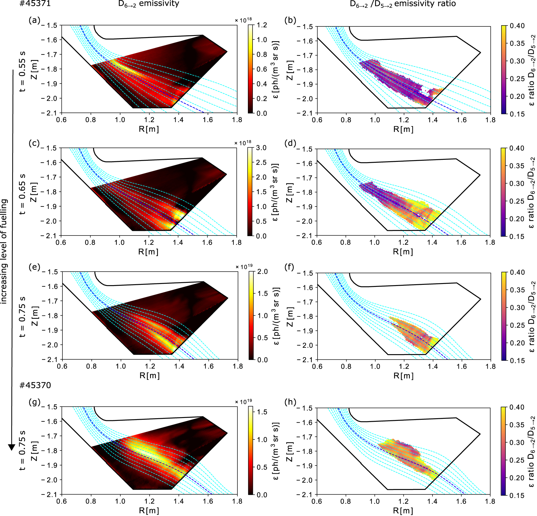
The corresponding D to D
to D emissivity ratios are shown in figures 9(b), (d) and (f). In the early phases of the density ramp, this ratio remains near a fixed value of
  . During the rapid increase in near-target emission, this ratio increases to
  , indicative of significant electron-ion recombination of deuterium as would be expected for electron temperatures well below 1 eV. This temperature upper bound is in agreement with the absence of Fulcher band emission in this region.
With increasing neutral fuelling, the electron-ion recombination region extends towards the X-point, as seen in figure 9. Eventually, the peak in recombination emission also moves in the direction of the X-point. This behaviour is found in the most strongly fuelled experiments in the first MAST-U campaign, such as discharge  45 370. This is depicted in figure 9(g) for the D
 line. The ratio D
 /D
/D of
of  found in figure 9(h) indicates that this emission region is dominated by atomic recombination. The reduction in recombination emission from the intensity peak towards the target suggests a decrease in electron density. We argue that this observation is unlikely to correspond to an increasing electron temperature towards the target, which would have the same signature [25]. A decrease in electron density upon the onset of electron-ion recombination at electron temperatures below 1 eV is in qualitative agreement with divertor imaging observations at JET [23].
The rise of electron-ion recombination dominated Balmer emission near target, and subsequent movement of this emission towards X-point, are also reflected in the spectroscopic measurements reported in earlier work [25]. However, especially in the presence of strike point splitting, interpretation of spectroscopic line ratios is not straight forward. In experiments where split emission branches are not as balanced as in discharge  45 371, recombination emission initiates at earlier times in the branch exhibiting lower electron temperatures or higher electron density. This perturbs line-integrated Balmer line analysis that assumes the measured emission originates from a region with single kinetic plasma parameters. Ratios of integrated profiles could suggest significant near-target electron-ion recombination, whereas this would not be the case for the branch carrying the dominant heat load. This emphasizes that direct detachment control based on, for instance, mid-n Balmer emissivity ratios, would benefit from sufficiently fast 2D emissivity reconstructions.
6. Outlook and discussion
6.1. Quantitative inference of plasma parameters
Moving forwards from the generic 2D description of emission processes in MAST-U detachment presented herein, the emission profiles, and their ratios, can be used as input to analysis routines that infer electron temperatures and densities, neutral and molecular densities, radiative power losses and ionisation and recombination rates [17, 18, 20–24]. The strong role of molecules complicates the experimental analysis with numerous processes possibly contributing to the same observed emission [5, 6, 22, 23]. This makes it more challenging to constrain the plasma parameter solution space using direct inference from the emissivity profiles alone.
One promising diagnostic to constrain electron density is the coherence imaging cell of the MWI itself [29], which will be explored in upcoming campaigns. 2D electron temperature and density constraints can also be derived from helium imaging. This approach was recently demonstrated using multi-spectral He-I imaging with the MANTIS system at TCV. Good agreement to co-local Thomson scattering measurements in majority deuterium plasmas was obtained in the operating space  eV
eV eV,
eV,  m
m m−3 [19]. Extension of this He-I emission analysis is required before application to MAST-U discharges, where temperatures in the detached phase are well bellow this threshold.
Even in the absence of direct quantitative parameter inference from emissivity profiles, they are still of value in validating codes such as SOLPS-ITER. First attempts at including molecular models in the recombination paths are ongoing to improve agreement of forward modelled emission with experimental data presented in this work.
6.2. The role of MWI in studying SXD performance
Initial SXD performance assessments are underway for MAST-U, and in experiments comparing the SXD to CD configurations, the desired reduction in heat load and detachment threshold is observed for the latter [49]. In upcoming campaigns the MWI will be part of a holistic diagnostic comparison between the SXD and CD, accounting for changes in e.g. divertor closure, target angle, baffle interaction, power into the SOL and impurity concentration. Its role here is primarily in disentangling the involved volumetric plasma-neutral and -molecule interactions for model refinement and validation.
The 2D perspective provided by MWI is particularly important for a few avenues of research. First, some emission processes and associated plasma-neutral and -molecule interactions have complex radial dependencies (see e.g. section 5.3), especially when radial transport is involved. Therefore, understanding of spatially resolved heat and particle deposition profiles, inferred from e.g. Langmuir probes and IR measurements, requires diagnostics which can resolve detachment processes in the whole divertor volume.
Secondly, one major hypothesized benefit of the SXD configuration is an increased parameter space (e.g. in upstream electron density, or power entering the SOL) in which the plasma behaves as detached [12]. Simulations performed for a simplified box geometry indicate that the detachment threshold (lower bound of the window) is mainly reduced by increased leg length and total flux expansion at the divertor target [13]. In experimental verification of these results, poloidally resolving the plasma emission is important in evaluating effective leg length and total flux expansion, which depend on the radial plasma distribution.
Lastly, the SXD is expected to exhibit reduced sensitivity of the radiation front equilibrium location to changes in parameters influencing detachment. Simulations indicate that strong magnetic field gradients and increased poloidal flux flaring reduce, respectively, parallel and poloidal detachment front location sensitivity [12, 13], damping the effect of upstream transients on the detachment state. In conjunction with bolometry measurements [50, 51], MWI inversions will be used to track emission front movements in the divertor chamber volume to verify these results.
6.3. Real-time radiation front control
Identification of different volumetric emission processes in this and earlier work [25], is used for real-time radiation front control. Along the lines of earlier work at TCV [30–32], preparations have commenced for the control of radiative detachment front proxies using a feedback on gas input. Several different sensors for control have been discussed in this work. The Fulcher band appears as a suitable novel signal for ionisation- and electron temperature front control near the detachment threshold. Upon successful testing, the existing framework will be extended to include MAR/MAD and recombination front tracking for deeper stages of detachment.
7. Conclusions
In this work quantitative multispectral imaging is used to interpret radiative detachment progression in MAST-U SXD L-mode plasmas during fuelling ramps. This magnetic configuration is expected to show reduced target heat loads as compared to conventional configurations through a larger poloidal flux expansion, increased leg length and smaller target angles [9–11]. The SXD configuration is also predicted to expand the parameter window where the plasma can be operated in detached divertor conditions [12, 13]. Poloidal emissivity maps of 6 deuterium Balmer lines, a C-III impurity triplet and an isolated spectral subset of the D2 Fulcher band, presented herein, add a 2D perspective to earlier spectroscopic identification of various detachment phases [25].
Emissivity profiles, from tomographic inversion of camera images, were validated by comparison to magnetics and spectroscopy. These are essential to understanding the spatial and spectral details of camera recorded emission. A close co-movement of the EFIT++ reconstructed magnetic separatrix and optical outer strike points from Balmer emission was found both in conventional and Super-X configurations. Synthetic spectrometer signals based on MWI inversions show a good agreement in absolute intensity with experimental spectroscopic measurements. We found that errors are limited to a few tens of percent over a wide range of upstream plasma electron densities and magnetic geometries.
Splitting of the SOL is found in imaging data for most Super-X experiments studied here. This is in qualitative agreement with target heat- and particle load measurements from infrared imaging and Langmuir probes. MWI analysis suggests that the branches radiatively detach at different upstream electron densities. 2D imaging will be instrumental in disentangling the volumetric particle-, heat- and momentum loss- and creation processes in the separate branches that lead to the spatially separated heat- and particle deposition profiles.
Progression of MAST-U detachment was studied here using core- and divertor fuelling ramps. The spectroscopically inferred sequence of detachment stages [25] is supported by 2D camera data, and here divided in four stages. At the lowest upstream densities studied, Fulcher band emission has a uniform profile from target to divertor throat, and carbon impurity emission peaks out of camera view. Both are sensitive to electron temperature and suggest  eV near the wall. We designate this stage as near-attached.
Increasing fuelling, the Fulcher band peak and electron-impact excitation dominated Balmer emission separate from the target in close co-movement. This is indicative of detachment of the deuterium ionisation front.
Below the electron-impact excitation dominated Balmer emission, 2D imaging reveals a radially broad emission region. This is attributed to MAR and MAD processes [25, 33]. The broadening is in qualitative agreement with SOLPS-ITER modelling for MAST-U [35] and experimental observations at JET [22]. With additional fuelling, this emission feature separates completely from the target, indicating plasma temperatures are insufficient ( eV) for significant D
 production through molecular charge exchange, which is part of the molecular reaction chains elevating the Balmer emission.
At the highest fuelling rates explored, Balmer line ratios indicate the onset of electron-ion recombination. The formed region of recombination dominated emission eventually separates from the target, suggesting a further electron density decrease towards the wall.
The emissivity reconstructions presented here can serve as a basis for spatially resolved reconstruction of electron temperatures and densities, ionisation- and recombination rates, as well as atomic and molecular densities. These are essential in the assessment of the performance of various alternative magnetic divertor configurations such as the Super-X.
Acknowledgment
This work has been carried out within the framework of the EUROfusion Consortium, funded by the European Union via the Euratom Research and Training Programme (Grant Agreement No. 101052200–EUROfusion). Views and opinions expressed are however those of the author(s) only and do not necessarily reflect those of the European Union or the European Commission. Neither the European Union nor the European Commission can be held responsible for them.
Authors Xiande Feng and Ray Sharples (Centre for Advanced Instrumentation, Durham) acknowledge support from EPSRC Grant EP/N024109/1.
Appendix A: Calibration of the MWI system
A.1. Absolute calibration
Quantitative plasma parameter inference, in particular through line ratio analysis, relies on the conversion of camera sensor counts to radiance. Absolute calibration of the MWI is a two step process addressed in earlier work on the MANTIS system [18]. In the first step, a calibrated broadband light source is used as input to an integrating sphere which uniformly fills the MWI optics. Filter curves are used to calculate the expected photon throughput. For each camera, a recorded raw image is now used to calculate a conversion factor from counts to radiance on a pixel-to-pixel basis. The calibration factors account for vignetting losses.
Strong out of band blocking is not just essential for blocking polluting emission lines under experimental conditions, but also to alleviate the problem of radiation outside of the transmission band contributing significantly to the calibration measurements. For uniform blocking at an OD4 level this pollution can reach up to 5 of the total photon flux at the sensor. While this is accounted for in calculating the photon throughput, it does mean that the calibration factors have contributions from wavelengths other than the target emission line wavelength, resulting in a systematic calibration error.
The transmission curve of the filter depends on the angle of incidence (aoi) of the light on the filter surface, which was designed to be between 0.5∘ and 5.5∘ [26]. As a result, the transmitted fraction of the emission line is pixel-dependent. To correct for this effect the broadband source is replaced by a spectral lamp emitting at the target wavelength. After applying the vignetting correction to the camera recording, the peak in the recorded signal should correspond to the peak of the filter transmission curve. Thus, we can extract a transmission mask with which experimental measurements are corrected to account for the aoi effect.
A.2. Spatial calibration
The inversion procedure described in appendix B requires a line-of-sight description for each pixel. Camera position, viewing direction and an intrinsic camera model are obtained for each camera separately using the Calcam software [52]. Calcam can provide a best fit camera model by comparison of characteristic vessel features in a detailed tokamak model to actual camera images. To further constrain the intrinsic camera model, which contains the focal length, relative pixel coordinates and coefficients for a rectilinear lens distortion model, ex-vessel checkerboard calibration images are used.
Appendix B: From camera image to emission profile
B.1. Synthetic camera models
Spatially resolved quantitative characterisation of the SOL in the MAST-U divertor using the MWI, demands a synthetic diagnostic to couple emissivity in the (R,Z)-plane to camera images. In this work, we assume toroidal asymmetries are averaged out over MWI acquisition time scales. The (R,Z)-plane is segmented into Nε polygons to allow discrete emissivity patterns of arbitrary intensity distribution.
To radiance  (ph/m
(ph/m sr s) on a sensor i of area Ai
depends on the incident spectral radiance
sr s) on a sensor i of area Ai
depends on the incident spectral radiance  , with ω the incident angle, and alignment of
  with the surface normal
  :
:

where we integrated over the collecting solid angle Ω, the detector area Ai
and wavelength λ. For a given set of  we can find the spectral radiance magnitude through integration over the discrete emissivity grid:

where dj
is the length of intersection between the path of  and the triangular emissivity cell j. Note that we here assume that the considered emission is isotropic and optically thin, meaning no significant fraction of the light is re-absorbed by the plasma and neutrals between the source and camera. There are various approaches to evaluating equation (B.1) numerically. What they have in common is that the resulting radiance is a linear function of
  so that we end up with a linear system of equations:

where we call the matrix Mij
the geometry matrix. While the same relation would hold for a non-toroidally symmetric emissivity grid, the assumption of toroidal symmetry makes the mathematical problem of estimating ε from a measurement of Φ, addressed in section B.2, computationally tractable and mathematically determined. While equation (B.3) neglects re-absorption of the considered emission line, optical thickness of other emission lines can significantly effect plasma parameter inference from ε through collisional radiative modelling. An important example for the present work is the influence of optically thick Lyman resonance lines on hydrogen Balmer line ratios at large (typically  m−3) neutral hydrogen density [33, 53].
Synthetic modelling of camera images from emissivities provided by SOL models and, reversely, estimating emissivities from camera images, relies on the availability of the geometry matrix M. The software package Cherab can evaluate equation (B.1) accounting for both finite sight line volume [46] and axis-symmetric reflection of light on wall elements [47]. Input to the code is the camera model obtained from Calcam. For every pixel  is approximated through weighted averaging of the grid coverage of
  infinitely thin sightlines casted through Monte Carlo importance sampling. Where a sightline meets a material surface the continuation of its path is drawn from a probability distribution linked to the chosen reflection model. The effect of light polarization is not taken into account. For JET, a metallic machine, it was found that the emissivity of near-target bright emission features can be overestimated by up to 20
 if reflection is not taken into account. Also, the reconstruction is found to place light in non-emitting areas of the poloidal grid. For the diffuse reflection properties of the MAST-U carbon wall this effect is expected to be of less influence [47, 54].
B.2. Tomographic inversion
In the context of interpreting experimental MWI data the radiance Φ is known with some uncertainty  . The quantity we are after is the emissivity ε in equation (B.3). A computationally efficient method which performs well for overdetermined limited-angle tomography problems is the simultaneous algebraic reconstruction technique (SART) [55]. In this work the SART algorithm is used to iteratively update ε from an initial estimate using the difference between the experimental image and forward modelled emissivity at step k:

with ηr a relaxation parameter. For in-depth discussions of reconstruction artefacts and how these can be alleviated we refer to earlier work on similar image processing [28, 46, 47, 54]. Equation (B.4) can be cast into matrix formulation for efficient processing. If the norm of the difference between two subsequent frames is limited, we can use the solution of the previous time step as a starting point for the next. The average inversion time for a 1032x772 image and a (R,Z)-grid with around 10 000 elements is a few seconds so that 2D emission profiles are available for intershot analysis and discharge performance assessment.