

Abstract
Objective. Recent attempts in developing brain–computer interface (BCI)-controlled robots have shown the potential of this area in the field of assistive robots. However, implementing the process of picking and placing objects using a BCI-controlled robotic arm still remains challenging. BCI performance, system portability, and user comfort need to be further improved. Approach. In this study, a novel control approach, which combines high-frequency steady-state visual evoked potential (SSVEP)-based BCI and computer vision-based object recognition, is proposed to control a robotic arm for performing pick and place tasks that require control with multiple degrees of freedom. The computer vision can identify objects in the workspace and locate their positions, while the BCI allows the user to select one of these objects to be acted upon by the robotic arm. The robotic arm was programmed to be able to autonomously pick up and place the selected target object without moment-by-moment supervision by the user. Main results. Online results obtained from ten healthy subjects indicated that a BCI command for the proposed system could be selected from four possible choices in 6.5 s (i.e. 2.25 s for visual stimulation and 4.25 s for gaze shifting) with 97.75% accuracy. All subjects could successfully complete the pick and place tasks using the proposed system. Significance. These results demonstrated the feasibility and efficiency of combining high-frequency SSVEP-based BCI and computer vision-based object recognition to control robotic arms. The control strategy presented here could be extended to control robotic arms to perform other complicated tasks.
Export citation and abstract BibTeX RIS
1. Introduction
The upper limb, which is involved in various daily activities such as eating and dressing, plays an important role in everyday life. However, at the same time, upper limb motor impairments are relatively common, which may occur as a consequence of diseases such as stroke and spinal cord injury (SCI) (Pollock et al 2014). For individuals with upper limb impairments, recovery of upper limb function is crucial to regaining their independence.
Recent advances in assistive robotic arms make it possible for disabled people with limited mobility to perform daily living independently (Brose et al 2010). But in case of individuals with upper extremity mobility impairments, the control of these assistive arms has always been challenging as they are usually controlled by traditional manual control approaches such as knobs, switches, keyboards, and joysticks. To facilitate the interaction between severely motor-impaired patients and assistive robots, brain–computer interface (BCI) technology has been introduced into robot control strategies (Millán et al 2010, Collinger et al 2013, McMullen et al 2014, Wodlinger et al 2015, Meng et al 2016, Chen et al 2018). The BCI technology can provide a new path to directly decode the human's brain signals to control external devices (Wolpaw et al 2002). Even though severely motor-impaired patients cannot make any sufficient movements of their upper limbs, they may still be capable of generating commanding brain signals, which can be used to build a BCI to drive a robotic arm. Therefore, a BCI-controlled robotic arm is a promising type of assistive device for severely motor-impaired people.
Among various methods of capturing brain signals, the electroencephalogram (EEG) is widely used in BCI research due to its advantages such as noninvasiveness, high temporal resolution, portability and inexpensiveness (Hwang et al 2013). The concept of device control via EEG-based BCIs has been proposed in previous studies, and successfully used to control real objects such as hand orthoses (Pfurtscheller et al 2000, Ortner et al 2011), prostheses (Müller-Putz and Pfurtscheller 2008), wheelchairs (Fernández-Rodríguez et al 2016) and robotic arms (Johnson et al 2010, Horki et al 2011, Onose et al 2012, Hortal et al 2015, Meng et al 2016, Zeng et al 2017, Zhang et al 2017, Chen et al 2018). Among these previously demonstrated EEG based BCI-controlled robotic arm systems, low-level control strategies (i.e. direct control or process control) were used to a great extent. In a low-level control strategy, however, users need to frequently send control commands, which may cause user fatigue. To mitigate this issue, some studies have attempted to control a robotic arm through a high-level control strategy (i.e. goal-oriented control) (McMullen et al 2014, Zeng et al 2017, Zhang et al 2017). These studies have shown that the high-level control strategy can make the total BCI-controlled robotic arm systems quicker and more accurate. In addition to a control strategy, prior attempts at the control of a robotic arm have mainly focused on the use of motor imagery-based BCIs (Onose et al 2012, Hortal et al 2015, Meng et al 2016). To satisfy the high number of degrees-of-freedom (DOFs) needed to achieve anthropomorphic control, however, more commands should be provided by the BCI.
Steady-state visual evoked potential (SSVEP)-based BCIs have attracted more and more attention in the field of BCI due to their high information transfer rate (ITR) and little user training (Vialatte et al 2010, Gao et al 2014). Compared with motor imagery-based BCIs, SSVEP-based BCIs are easier to encode with more commands without any extensive training and show promising potential in high-speed communication. For example, Chen et al reported an ITR of 105 bits min−1 in a 45-target SSVEP-based BCI system (Chen et al 2014). More recently, higher ITRs were reported in SSVEP-based BCIs. Chen et al (2015a) and Nakanishi et al (2018) reported an ITR of 267 bits min−1 and 325.33 bits min−1, respectively, in a 40-target system. SSVEP-based BCIs have been used for initial studies to control a robotic arm (Horki et al 2011, Chen et al 2018) and an exoskeleton (Kwak et al 2015). Such previous efforts have mainly adopted low- and medium-frequency stimuli. Although stimulation in these frequency ranges evoke SSVEPs with a large amplitude, it is annoying and tiring for users. A possible solution to overcome this problem is to use high-frequency stimulation. High-frequency stimuli can decrease visual fatigue caused by flickering, thus making the SSVEP-based BCI a more comfortable system (Wang et al 2005, Diez et al 2011, Volosyak et al 2011).
In this study, we presented a novel BCI-based high-level robotic arm control system. The novelty of our approach lies in the combination of a high-frequency SSVEP-based BCI with computer vision-based object recognition for controlling a robotic arm. The proposed system recognizes and locates objects by computer vision from an Intel RealSense SR300 camera, and selects target object by a high-frequency SSVEP-based BCI. Then the robotic arm autonomously picks the selected target object and placs it at the predefined destination without requiring moment-by-moment supervision by the user. Additionally, to further increase the practicality of the proposed system, a portable and wireless EEG device is used to record SSVEPs, and a training-free method is adopted to detect SSVEPs. Both offline and online experiments were conducted to demonstrate the feasibility of the proposed system.
2. Methods
2.1. Subjects
Ten healthy subjects (six males and four females; aged 23–29 years), with normal or corrected-to-normal vision, participated in this study. Each subject signed his or her written informed consent prior to the experiment. This study was approved by the Research Ethics Committee of Chinese Academy of Medical Sciences. During the whole experiment, subjects were seated in a comfortable chair in a normal office room approximately 1 m in front of the visual stimulator.
2.2. EEG data acquisition
EEG data were acquired using a portable EEG amplifier (Neuracle, China) at a sampling rate of 1000 Hz. Nine electrodes over parietal and occipital areas (Pz, PO5, PO3, POz, PO4, PO6, O1, Oz, and O2) were used to record SSVEPs. The ground electrode was placed between Fz and FPz. The reference electrode was located at the vertex. All electrodes were placed according to the international 10–20 system. Electrode impedances were kept below 10 kΩ. Event triggers (i.e. stimulus onset) generated by the stimulus program were recorded on an event channel synchronized to the EEG data.
2.3. System description
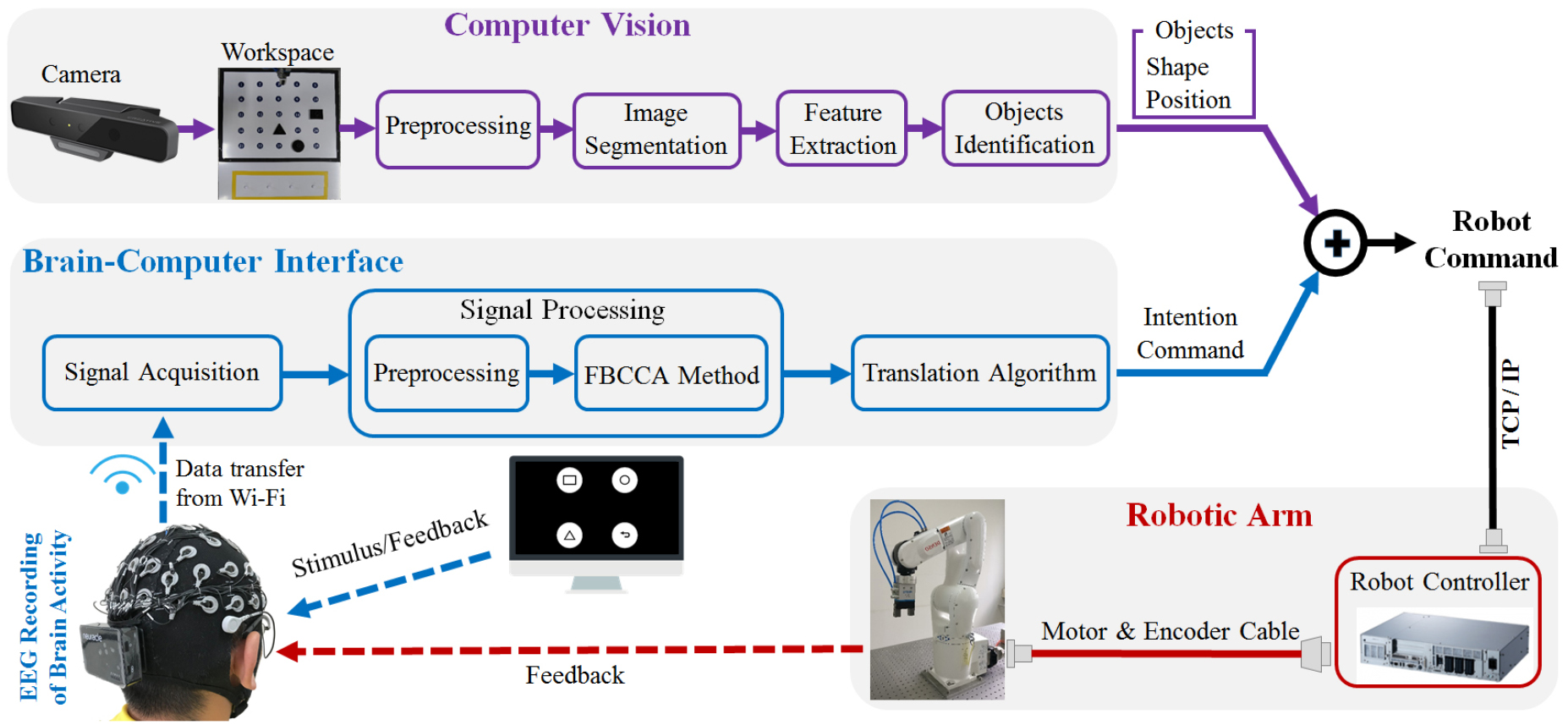
The proposed high-level robotic arm control system mainly consisted of a computer vision subsystem, an SSVEP-based BCI, and a robotic arm. Figure 1 shows the experimental environment. The computer vision was used to detect objects in 3D space, while the SSVEP-based BCI allowed the user to select one of these objects to be acted upon by the robotic arm. The robotic gripper moved from the initial waiting position (0 mm, 0 mm, 98 mm) to 83 mm above the selected object. Subsequently, the gripper went down to grasp the selected object in the black region, lifted it, and placed it in the pre-defined position in the yellow region of the workspace. Then the gripper moved to 83 mm above the object and waited for the next command. The SSVEP-based BCI subsystem and the computer vision subsystem ran on one computer with MATLAB and communicated with the robotic arm subsystem via TCP/IP. Figure 2 shows the schematic of the proposed system.

Figure 1. The experimental environment of the high-level robotic arm control system.
Download figure:
Standard image High-resolution image
Figure 2. Schematic of the high-level robotic arm control system.
Download figure:
Standard image High-resolution image2.3.1. Robotic arm.
The robotic arm was a six-axis industrial manipulator Denso VS-060 equipped with a two-finger pneumatic gripper (FESTO, DHPS-25-A). A mechanical coupling was designed to integrate the robotic arm and the gripper. A RC8 controller, which was governed by WINCAPS III software, controlled the robotic arm. A board positioned directly in front of the robotic arm served as the workspace for the robotic arm action. The workspace (550 mm × 600 mm) was segmented into two regions (the black region and yellow region in figure 1). The black region contained a 5 × 5 grid of 25 blue-coded circles, which represented 25 locations. The 25 locations in the 5 × 5 grid were pre-taught. Three plastic objects with different shapes (rectangle, circle, triangle) were randomly placed in three of the 25 different locations. Subjects were asked to pick up these objects and place them in the yellow region with the proposed system.
2.3.2. Computer vision.
The computer vision was responsible for identifying and locating the three objects in the workspace for robotic arm action. An Intel RealSense SR300 camera was used to capture RGB images from the workspace. The camera was placed on a tripod at approximately 1 m above the workspace. The camera streamed to a computer through USB 3.0. First, the RGB image was converted to grayscale intensity image. A median filter was used to reduce fat-tailed noise. Then the image was converted to a binary image. Second, to further remove noise from the image, all connected regions, which were less than 3000 pixels, were deleted. Third, the image was equally divided into 5 × 5 equal sized sub-images. Boundaries of holes inside objects in the binary sub-images were extracted and were then applied to determine the positions of the three objects in the workspace. Last, the distances between all edge points and the centroid were used as features, which provided good discrimination ability and were used to determine the shapes of the three objects. The output from this classification included the shape and position of these objects.
2.3.3. SSVEP-based BCI.
A four-target SSVEP-based BCI was developed to select one of these objects to be acted upon by the robotic arm. The proposed BCI was operated in a synchronous way for sending commands. As shown in figure 3, the user interface was a 2 × 2 stimulation matrix containing four commands. The first three commands were used to choose the corresponding object for robotic arm action, respectively. The remaining command allowed the user to undo the last operation. The undo operation could be repeated until the operations history list was empty. These commands were tagged with 30, 31, 32, 33 Hz for the target on top left, to the top right, then lower left and to the target on the lower right, respectively. A sampled sinusoidal stimulation method (Manyakov et al 2013, Chen et al 2014) was adopted to present visual flickers on a 27-inch liquid-crystal display (LCD) monitor with a resolution of 1920 × 1080 pixels and a refresh rate of 120 Hz. The stimulus program was developed under MATLAB using the Psychophysics Toolbox Version 3 (Brainard 1997). The object selected by the SSVEP-based BCI and the object shape and position derived from the computer vision were translated into the robotic arm motion commands, which were then sent to the RC8 controller. The robotic arm automatically picked the desired object and placed the object at the desired location.

Figure 3. (a) The user interface of the high-level robotic arm control system. (b) The frequency values for all targets.
Download figure:
Standard image High-resolution image2.4. Offline experiment
The offline experiment consisted of three blocks. Each block contained a randomized order of 40 trials, and every target was presented ten times. Therefore, there were 30 trials for each target. Each trial started with a visual cue (i.e. the desired target was surrounded by a red square) indicating a target stimulus. The cue appeared for 1 s on the screen. Subsequently, all stimuli started to flicker on the screen concurrently and lasted 4 s. Subjects were asked to avoid eye blinks during the stimulation period. After stimulus offset, the user interface of the proposed SSVEP-based BCI appeared for 2 s before the next trial began. To avoid visual fatigue, there was a rest of several minutes between two consecutive blocks. The robotic arm was not activated during the offline experiment. In additional, we also tested the performance of the computer vision subsystem. We recorded 200 video frames with the three objects while varying the positions of the objects in the workspace.
2.5. Online experiment
In the online experiment, each trial lasted 6.5 s including 2.25 s for visual stimulation and 4.25 s for gaze shifting. The online experiment included a cued robot movement control task and a free robot movement control task. The cued robot movement control task included ten blocks, each block contained four trials corresponding to all four targets indicated in a pseudo-random order. The cue for the next target appeared right after the stimulus offset. Visual feedbacks were provided to the subjects in real time. The target object was marked by a red circle. At the same time, the robotic arm immediately picked the target object and placed the object at the desired location. The free robot movement control task required subjects to select objects in a fixed order (i.e. rectangle, circle, triangle) without visual cues. The task was repeated five times for each subject.
2.6. EEG data analysis
Data epochs, which comprised nine-channel SSVEPs, were extracted according to event triggers generated by the stimulus program. Considering a latency delay in the visual system (Di Russo and Spinelli 1999), the data epochs for offline and online experiments were respectively extracted in [0.14 s 4.14 s] and [0.14 s 2.39 s], where the time 0 indicated stimulus onset. For all epochs, linear trends were first removed and then a notch-filtered was applied to remove the power line interference. All epochs were then down-sampled to 250 Hz.
The amplitude spectrum and signal-to-noise ratio (SNR) of SSVEPs were first analyzed in this study. The amplitude spectrum  was calculated by fast Fourier transform. The SNR in decibels (dB) was defined as the ratio of the amplitude at the stimulation frequency to the mean amplitude of the ten neighboring frequencies (i.e. five frequencies on each side):

The amplitude spectrum and SNR of SSVEPs were analyzed using the 4 s long epochs from the offline experiment. For each stimulation frequency, 30 trials were first averaged for improving the SNR of SSVEPs. The mean amplitude spectrum was calculated by averaging across the amplitude spectra corresponding to nine channels and ten subjects. SNR was then calculated using the mean amplitude spectrum.
Canonical correlation analysis (CCA) has been widely used for detecting SSVEPs (Bin et al 2009, Chen et al 2013, 2014, 2017). Considering two multidimensional variables  ,
,  , and their linear combinations
  and
and  , CCA finds the weight vectors
  and
and  , which maximize the correlation between
  and
and  by solving the following problem:

The maximum of  with respect to
  and
and  is the maximum canonical correlation. Here,
  refers to the set of multi-channel EEG signals and
  refers to the set of sine-cosine reference signals that have the same length as
  . The sine-cosine reference signals
  are set as

where  is the stimulation frequency,
  is the number of harmonics, and
  is the sampling rate. In this study,
  ,
,  was the
  th stimulation frequency. To detect the SSVEP frequency, CCA calculates the canonical correlation between multichannel EEG signals and the sine-cosine reference signals at each stimulation frequency. The frequency of the sine-cosine reference signals with maximal canonical correlation is considered as the SSVEP frequency
To incorporate fundamental and harmonic frequency components to improve the detection of SSVEPs, we recently proposed a filter bank CCA (FBCCA) method and demonstrated its superiority over the standard CCA method (Chen et al 2015b). Here we adopted the FBCCA method to classify the four-class high-frequency SSVEPs. The FBCCA method comprises three stages: filter bank analysis, CCA between SSVEP sub-band components and sinusoidal reference signals, and target identification. The first stage decomposes the original EEG signals  into sub-band components (
 ). The second stage applies the standard CCA process to each of the sub-band components separately, resulting in correlation values between the sub-band components and sine-cosine reference signals (
 ).
).
A correlation vector  was defined as follows:

where  indicates the correlation coefficient between
  and
and  .
.  and
and  ,
,  , were linear combination coefficients obtained by the standard CCA between
  and
and  . An ensemble classifier was used to combine features derived from each sub-band component. In practice, the following weighted correlation coefficient
  was used as the feature for target identification:

where  is the index of the sub-band. The weights for the sub-band components were defined as follows:

where  and
and  are constants that maximize the classification performance. Here we determined
  and
and  using a grid search method using an offline analysis. Finally,
  corresponding to all stimulation frequencies (i.e.
  ) were used for determining the frequency of the SSVEPs. The frequency of the reference signals with the maximal
  is considered to be the frequency of the SSVEPs.
2.7. Performance evaluation
Classification accuracy, completion time, and the ITR were used to evaluate the performance of the proposed system. In this study, the ITR in bits min−1 was calculated as follows:

where  is the number of classes (i.e. four in this study),
  is the classification accuracy, and
  (seconds/selection) is the time needed to deliver each command including gazing time and gaze-shifting time. The gazing time equals to the visual stimulation time. The gaze-shifting time represents the time to switch from the current gaze target to the next target. A 4.25 s gaze-shifting time was adopted in this study.
3. Results
3.1. Offline analysis of system performance
3.1.1. Computer vision.
During offline analysis, the computer vision could correctly identify the three objects in all 200 recorded frames. To illustrate this subsystem, we applied it to an example image and showed the output at each step (see figure 4). By mapping the 25 segmented sub-images with the 25 pre-taught locations on the workspace, the three objects' positions could be determined. For each of the objects, the distances between all edge points and the centroid were calculated, and then these distances were normalized by the maximum value. As shown in figure 4, all the normalized distances were above 0.7 for the circle object, while there were three vertexes for the triangle object but four vertexes for the rectangle object. The object shape could be determined according to the normalized distances.

Figure 4. An example implementation of the proposed computer vision subsystem.
Download figure:
Standard image High-resolution image3.1.2. SSVEP-based BCI.
Figure 5(a) shows the mean amplitude spectrum of SSVEPs at 30 Hz. The fundamental component showed the highest amplitude ( ). The amplitude of harmonics dropped significantly as the response frequency increased (first harmonic:
  , second harmonic:
  ). Figure 5(b) shows the corresponding SNR of SSVEPs at 30 Hz. The SNR of SSVEPs decreased slowly and steadily as the response frequency increased (fundamental: 16.72 dB, first harmonic: 14.59 dB, second harmonic: 9.16 dB). This property was also applicable to other stimulation frequencies. Figure 6(a) shows the classification accuracy of the standard CCA method with different data lengths and different numbers of harmonics in the reference signals. The classification accuracy increased in step with the data length until it reached a stable level. Furthermore, the classification accuracy increased with the number of harmonics. Figure 6(b) shows the relationship between the classification accuracy and different numbers of harmonics with a data length of 2.25 s, which was used in the online experiment. The highest classification accuracy was obtained when
  . A one-way repeated-measures ANOVA revealed a significant effect of number of harmonic on accuracies (F(3, 27) = 6.60, p = 0.02). Pairwise comparisons revealed significant difference between
  and all the other
  values (
 : 89.00%,
  ,
,  ,
,  ). Therefore, this study used
  for all standard CCA processes in the FBCCA method.

Figure 5. Amplitude spectrum (a) and SNR (b) of SSVEPs at 30 Hz. The red circles indicate the fundamental and harmonic frequencies of 30 Hz (i.e. 30, 60, and 90 Hz).
Download figure:
Standard image High-resolution image
Figure 6. (a) Classification accuracy of the standard CCA method corresponding to different data lengths and different numbers of harmonics. (b) Classification accuracy with a data length of 2.25 s. The error bars indicate standard deviations.
Download figure:
Standard image High-resolution imageIn this study, the stimulation frequencies ranged from 30 to 33 Hz with a frequency interval of 1 Hz. According to harmonic analysis of the standard CCA method, amplitude spectrum and SNR of SSVEPs (see figure 5), the frequency range within [30 Hz 90 Hz] was selected for the filter bank in this study. The  th sub-band started from the frequency at
  Hz and ended at 90 Hz. The parameters of the FBCCA method (i.e.
  in equation (5) and
  in equation (6)) were determined by a grid search method where
  ,
,  , and
, and  were limited to [0:0.25:2], [0:0.25:1], and [1:1:2] respectively. The parameters that led to the highest ITR were chosen for the online experiment. Figure 7 shows the classification accuracy (figure 7(a)) and ITR (figure 7(b)) with different
  and
and  for the FBCCA method with a data length of 2.25 s and
  . The optimal
  ,
,  , and
, and  were 1.75, 0.25, and 2 respectively. In this study, the FBCCA method is the same as the standard CCA method when
  .
.

Figure 7. (a) Classification accuracy (%) and (b) ITR (bits min−1) with different a and b for the FBCCA method with a data length of 2.25 s and N = 2. The black circle indicates the location of the highest ITR among different combinations of a and b.
Download figure:
Standard image High-resolution imageFigure 8 shows the classification accuracy and ITR across all subjects with different data lengths (from 0.25 to 4 s with a step of 0.25 s). As shown in figure 8, the FBCCA method outperforms the standard CCA method. These results indicate that the employment of the FBCCA method can also improve the performance of the high-frequency SSVEP-based BCI. Paired t-tests showed that the classification accuracies of the two methods showed significant differences between 0.5 s and 2.75 s (p < 0.05). The differences between the two methods in ITR were significant from 0.5 s to 3 s (p < 0.05). The highest ITR was obtained with a data length of 2.25 s for the FBCCA method (i.e. 15.73 bits min−1). Thus the data length of 2.25 s was selected for the online experiment.

Figure 8. Classification accuracy (a) and ITR (b) for the FBCCA method and the standard CCA method as a function of data length. The asterisks indicate significant differences (p < 0.05) between the two methods by paired t-tests.
Download figure:
Standard image High-resolution image3.1.3. Robotic arm.
Once initiated by the proposed SSVEP-based BCI, the robotic arm automatically performed the complex pick and place task. It was necessary to estimate the time required for the completion of a pick and place operation. The robotic arm picked an object from the black region of the workspace and placed it down in the yellow region of the workspace (see figure 1). There were 25 possible locations for the black region and only three possible locations for the yellow region. By analyzing the execution time of the 75 pick and place operations, a better estimation of the time required for the completion of a pick and place operation could be obtained. The average execution time was 3.71 ± 0.26 s. The minimal and maximal execution times were 3.14 s and 4.24 s, respectively. In order to avoid command overcrowding in this study a 4.25 s gaze-shifting time was thus selected for the online experiment.
3.2. Online system performance
This study tested the entire system using two online robot control tasks (i.e. cued robot movement control task and free robot movement control task). A fixed stimulus duration of 2.25 s and a gaze-shifting duration of 4.25 s were used for all subjects, leading to the selection speed of 6.5 s per command. During online experiments, the computer vision could correctly identify the three objects. Table 1 lists the results of the online cued robot movement control task. The averaged accuracy across all subjects was 97.75% ± 3.22%, leading to an averaged ITR of 17.00 ± 2.02 bits min−1. Table 2 lists the results of the free robot movement control task. Due to the adoption of the high-level control strategy, all ten subjects were able to control the proposed system without practice sessions. Furthermore, all subjects could successfully complete the free robot movement control task. The average completion time needed to complete the free robot movement control task five times was 104.00 ± 12.63 s (range: 97.50–136.50 s). The number of commands used for controlling the robotic arm to complete the free robot movement control task was 15–21. Two subjects (S6 and S8) made one error and one subject (S7) made two errors. They correctly selected the undo command to withdraw the wrong selection. To gain more insight into the process of task execution, figures 9(a) and (b) show the gripper trajectory in Cartesian workspace and the corresponding snapshots during the free robot movement control task, respectively. All subjects were asked to operate objects in a fixed order (i.e. rectangle, circle, triangle). These results demonstrated the effectiveness of the proposed system.
Table 1. Results of the cued robot movement control task.
| Subject | Accuracy (%) | ITR (bits min−1) |
|---|---|---|
| S1 | 97.50 | 16.54 |
| S2 | 92.50 | 13.82 |
| S3 | 100.00 | 18.46 |
| S4 | 100.00 | 18.46 |
| S5 | 100.00 | 18.46 |
| S6 | 92.50 | 13.82 |
| S7 | 100.00 | 18.46 |
| S8 | 100.00 | 18.46 |
| S9 | 100.00 | 18.46 |
| S10 | 95.00 | 15.09 |
| Mean ± SD | 97.75 ± 3.22 | 17.00 ± 2.02 |
Table 2. Results of the free robot movement control task.
| Subject | Trial length (s) | Total number of trials | Completion time (s) |
|---|---|---|---|
| S1 | 6.5 (2.25 + 4.25) | 15 | 97.50 |
| S2 | 6.5 (2.25 + 4.25) | 15 | 97.50 |
| S3 | 6.5 (2.25 + 4.25) | 15 | 97.50 |
| S4 | 6.5 (2.25 + 4.25) | 15 | 97.50 |
| S5 | 6.5 (2.25 + 4.25) | 15 | 97.50 |
| S6 | 6.5 (2.25 + 4.25) | 17 | 110.50 |
| S7 | 6.5 (2.25 + 4.25) | 21 | 136.50 |
| S8 | 6.5 (2.25 + 4.25) | 17 | 110.50 |
| S9 | 6.5 (2.25 + 4.25) | 15 | 97.50 |
| S10 | 6.5 (2.25 + 4.25) | 15 | 97.50 |
| Mean ± SD | — | 16 ± 1.94 | 104.00 ± 12.63 |

Figure 9. Gripper trajectory in the Cartesian workspace (a) and the corresponding snapshots (b) during the free robot movement control task.
Download figure:
Standard image High-resolution image
4. Discussion
In this study, we combined SSVEP-based BCI and computer vision to develop a system that allowed users to convey high-level control signals to a robotic arm. The computer vision was responsible for detecting objects in the workspace, while the SSVEP-based BCI was used to select one of these objects for the robotic arm action. Once the desired object had been selected by the SSVEP-based BCI, the robotic arm automatically picked the desired object and placed it at the desired location. Additionally, the proposed system also allowed users to undo system errors (i.e. incorrectly selected object). This high-level control strategy freed users from the process of robotic arm navigation and thus required less mental effort from the users. All ten subjects quickly learned to operate the proposed system. BCI-controlled robotic arm systems have largely focused on a low-level control strategy (Johnson et al 2010, Horki et al 2011, Onose et al 2012, Hortal et al 2015, Meng et al 2016, Chen et al 2018). Notably in recent studies on BCI-controlled robotic arm systems, computer vision has been combined with BCIs using electrocorticography (EcoG) (McMullen et al 2014), P300 (Zhang et al 2017), and motor imagery (Zeng et al 2017). The present study attempted to combine SSVEP-based BCI with computer vision to control a robotic arm. The proposed system worked well using this high-level control strategy and obtained an averaged accuracy of 97.75%. Furthermore, all subjects could successfully finish the pick and place task using the proposed system. The number of commands needed to complete the free robot movement control task, which could be considered an indirect measure of mental workload, was 15–21. Reduction of mental effort due to using the high-level control strategy would be important for moving the proposed high-level robotic arm control system from laboratory demonstration to practical applications. Although high-level control exhibited advantages over low-level control or direct control, high-level control also had limitations. High-level control required that the situation was known. The major advantage of low-level control was that it allowed operation in an unknown environment. Therefore, our future work will focus on incorporating both levels of control into the system architecture of the BCI-controlled robotic arm system, which will allow users to freely switch between the two levels of control (i.e. shared control). Currently, the control strategies of BCI-controlled robots are mainly divided into low-level control, high-level control, and shared control. Although these three control strategies have been studied, which one is easier to learn is an unanswered question (Fernández-Rodríguez et al 2016). In future research, we will try to build a BCI-controlled robotic arm system based on these three control strategies, and then investigate the relationship between system performance and usage time.
In addition to the high-level control strategy, the use of a high-frequency SSVEP-based BCI was integral for the proposed system. Given the actual application of controlling a robotic arm to operate objects in a workspace, the selected BCI should provide accurate and efficient control of a robotic arm. Therefore, an SSVEP-based BCI was adopted in the proposed system. Although several studies have attempted to control a prosthetic or a robotic arm using SSVEP-based BCIs (Müller-Putz and Pfurtscheller 2008, Horki et al 2011, Ortner et al 2011, Chen et al 2018), most of these studies utilized low-frequency stimuli to encode commands since low-frequency stimuli could elicit strong SSVEPs and then facilitate the robot control. However, low-frequency stimuli were easier to induce user fatigue during extended usage. Given high-frequency visual flicker could reduce visual fatigue and discomfort, the current design of the visual stimulator adopted stimuli flickering in the high-frequency range (i.e. 30–33 Hz). In this study, the FBCCA method was used to detect target frequency of SSVEPs. Although the robustness of the FBCCA method in detecting low-frequency SSVEPs has been proved (Chen et al 2015b), far less is known about its performance for high-frequency SSVEPs detection. In this study, an averaged accuracy of 97.75% was obtained across ten subjects. The high accuracy of the proposed system not only indicated that the FBCCA method was suitable for detecting high-frequency SSVEPs, but also verified that high-frequency SSVEP-based BCI could provide accurate control of a robotic arm. Additionally, the FBCCA method did not require any training data for individualized calibration and then made the proposed SSVEP-based BCI more practical for real-life scenarios. Furthermore, the proposed SSVEP-based BCI adopted a small lightweight and wireless EEG device to measure SSVEPs, which further fostered the transition of the proposed system from laboratory settings to practical applications. The proposed SSVEP-based BCI adopted synchronous control protocols where the period of control was initiated by the system. However, asynchronous control protocols, in which users make self-paced decisions on when to start or stop the system, are more flexible and natural for controlling robotic arms. Future development of the proposed BCI-controlled robotic arm system is expected to incorporate asynchronous BCI into its system architecture.
In this study, computer vision was used to identify objects in the workspace. Each successful trial required the computer vision to detect the object position and shape accurately. Both offline analysis and online testing demonstrated that the three objects could be accurately identified through the computer vision. The high accuracy of the computer vision could be mainly attributed to the following factors: good image quality, simple 2D image recognition, and precise object position operated by the robotic arm. To further increase the practicality of the proposed system for real life scenarios, the proposed system needs more robust computer vision. Future work will focus on incorporating data from depth sensors to identify a wider variety of objects and integrating computer vision into BCI via shared control (He et al 2018). With continual improvements in the aforementioned technologies, robotic arm control should become easier and more effective in the near future.
5. Conclusion
This study investigated the combination of high-frequency SSVEP-based BCI and computer vision to control a robotic arm to complete a pick and place task. The offline analysis results showed that the FBCCA method significantly outperformed the CCA method for high-frequency SSVEPs. The online results indicated that a command for the proposed system could be selected from four possible choices in 6.5 s (i.e. 2.25 s for visual stimulation and 4.25 s for gaze shifting) with 97.75% accuracy. These results demonstrated the capability of the proposed system and the corresponding algorithms. Furthermore, subjects used an average 16 ± 1.94 commands to control the robotic arm to complete the free robot movement control task. The combination of high-frequency SSVEP-based BCI and computer vision can reduce user mental effort and allow longer periods of time to use the proposed system.
Acknowledgments
This work was supported by National Natural Science Foundation of China under Grant (No. 61603416, No. 61431007), Young Elite Scientists Sponsorship Program by CAST (No. 2015QNRC001), the Fundamental Research Funds for the Central Universities (No. 3332018191), and National Key R&D Program of China under Grant (No. 2017YFB1002505).