


Abstract
The beating of cilia and flagella is essential to perform many important biological functions, including generating fluid flows on the cell surface or propulsion of micro-organisms. In this work, we analyze the motion of isolated and demembranated flagella from green algae Chlamydomonas reinhardtii, which act as ATP-driven micro-swimmers. The beating flagella of Chlamydomonas exhibit an asymmetric waveform that is known to involve the superposition of a static component, corresponding to a fixed, intrinsic curvature, and a dynamic wave component traveling from base-to-tip at the fundamental beat frequency, plus higher harmonics. Here, we analyse free, hinged and clamped axonemes using principal component analysis. The axonemal motion is described with a high degree of accuracy, taking into account only the first four dominant eigenmodes. Our analysis suggests that the wave motion can be alternatively described with Fourier modes, with a wavelength λ, larger than the length of the filament L (λ/L ≈ 1.3). Within this representation, we demonstrate that the main base-to-tip traveling wave component coexists with standing waves. Finally, we report the effect of calcium on the constituting wave components and find that the static mode is the most sensitive component to the calcium ion concentration.

Original content from this work may be used under the terms of the Creative Commons Attribution 4.0 licence. Any further distribution of this work must maintain attribution to the author(s) and the title of the work, journal citation and DOI.
1. Introduction
Cilia and flagella are slender hair-like appendages that protrude from the cell surface and act as a fundamental motility unit by performing periodic whip-like motion to provide driving force for fluid transport or cell locomotion [1, 2]. Typical examples are mucociliary clearance in mammalian airways to protect the respiratory system from harmful inhaled materials [3, 4], transport of cerebrospinal fluid in the brains of mammals [5], transport of the egg to the uterus [6], cilia-driven flow determining the left–right asymmetry in the embryonic node [7], or propulsion of micro-organisms such as paramecium, spermatozoa, or the unicellular biflagellate alga Chlamydomonas reinhardtii (C. reinhardtii) [8–12]. The breast-stroke like motion of two flagella in C. reinhardtii, illustrated in figures S1(A) and (B) (https://stacks.iop.org/NJP/24/053025/mmedia), pulls the swimmer forward in the ambient fluid.
The core structure of cilia and flagella, known as axoneme, has a highly conserved cylindrical architecture, as described in figures S1(C) and (D). The diameter of an axoneme is about 200 nm and doublet microtubules (DMTs) are spaced 30 nm away from each other. The beating pattern of flagella varies among different species. Flagella isolated from green algae C. reinhardtii beat by asymmetric curvature waves propagating along the contour length in a base-to-tip direction [13–16]. These asymmetric curvature waves, which are similar to the flagellar waveform in intact C. reinhardtii cells (see figures S1(A) and (B) and 1(C)), result in a curved swimming trajectory. They can be decomposed into multiple mode components [13–19]: (1) a semi-circular static mode resulting from averaging the flagellar shapes over a beat cycle, (2) a main dynamic mode describing a base-to-tip wave propagation at the fundamental beat frequency f0, and (3) a second harmonic component at frequency 2f0, which modulates the waveform of the principal base-to-tip traveling wave. The static mode and the second harmonic of the waveform contribute to the axonemal rotational velocity [16, 20, 21] and in the absence of these two components, the axoneme swims in a straight trajectory [22, 23]. The magnitude of different components contributing to the flagellar waveform depends on the concentration of calcium ions which are found to be one of the key players in shaping the flagellar beat. Experiments by Bessen et al [22, 23] with axonemes isolated from C. reinhardtii have shown that high Ca2+ concentration triggers a transition from asymmetric to symmetric waveform. A similar calcium-dependent modification in the wave symmetry was also observed in ATP-reactivated C. reinhardtii cells where two flagella are demembranated using detergents [24]. Interestingly, to reverse the direction of wave propagation during a photo-phobic response to an intense light, C. reinhardtii cells change the internal level of Ca2+ ions to switch from asymmetric forward beating pattern to a symmetric reverse mode of beating [25–28].

Figure 1. An isolated, freely beating axoneme, with the basal end shown as a blue dot and the distal tip as a white dot. (A) An instantaneous shape. The tangent vector t(s) at s = 0 defines the X-direction of the swimmer-fixed frame and the corresponding normal vector n(s) defines the Y-direction. (B) Traces of the basal end (originally connected to the intact C. reinhardtii cell, blue trace) and the distal tip (white trace) of the axoneme tracked for 900 ms. (C) Curvature waves initiate at the basal end of the axoneme and propagate toward the distal tip at a frequency of f0 = 18.17 ± 0.01 Hz. (D) The color-coded time projection of the axoneme shows a circular swimming trajectory. Here [ATP] = 80 μM and [Ca2+] = 0.
Download figure:
Standard image High-resolution imageTheoretical work devoted to the problem has led to intriguing predictions. The analysis of Camalet et al [19, 29] has shown that in a model cilium, designed as a symmetric motor-filament pair with a symmetric force-generating system, the wave direction depends strongly on the boundary conditions. By changing the ATP concentration, the system undergoes a dynamic instability (a Hopf bifurcation) and traveling waves emerge. This analysis shows that boundary conditions can play a very important role: for a base-clamped filament, waves propagate in the tip-to-base direction whereas for the base-hinged and free filaments the wave direction is opposite. Furthermore, simulations of simplified models [30–33] also highlight the importance of the boundary condition and show that by increasing the dynein motors-induced axial stresses in a base-clamped model cilium, the wave direction can switch. However, this switching was not observed in their model for a hinged cilium.
In this work, to understand the effect of the boundary conditions experimentally in a model system that is close to the real flagellum, we combined high-precision high-speed phase contrast microscopy (1000 fps) with image processing and analytical analysis to quantitatively describe the wave patterns of beating axonemes isolated from C. reinhardtii. Our analysis of the motion in 2D using principal component analysis (PCA) shows that the motion of axonemes is very accurately captured by the four dominant modes, consistent with previous works [20, 34, 35]. Furthermore, analyzing the PCA modes with Fourier analysis reveals that the main base-to-tip propagating wave coexists with standing waves. We found that the amplitude of the standing waves depends on the boundary conditions and was higher in non-rotating clamped axonemes that are attached from the distal region to the substrate and can reflect the dominant base-to-tip traveling wave. To quantitatively investigate how the wave components depend on calcium, we performed experiments with different calcium concentrations. When the calcium concentration is increased from 10-4 mM to 1 mM, the static mode decreases by about 85% and triggers the transition from a circular to a straight swimming motion. Finally, the analysis of a few cases of freely beating flagella in intact C. reinhardtii cells demonstrates the coexistence of the main dominant wave with standing waves. We close the manuscript with a conjecture on the origin of the standing waves.
2. Results
We used established protocols to isolate flagella from C. reinhardtii wild type cells, and demembranated them using non-ionic detergents [8, 36]. These naked flagella (axonemes), can be reactivated at various ATP concentrations (see materials and methods). ATP powers dynein molecular motors that convert chemical energy into mechanical work by sliding adjacent DMTs relative to each other, as illustrated in figures S1(C) and (D) [37–40]. However, structural constrains do not allow DMTs to slide freely. Instead, sliding is converted into rhythmic bending deformations that travel along the contour length of axonemes in the base-to-tip direction. To quantify these curvature waves, we tracked the axonemes over time using the gradient vector flow (GVF) technique [41, 42] (see materials and methods and figure S2). In our experiments, we vary two parameters, namely ATP and Ca2+ concentration, as discussed below. We focus on the examples where axonemes swim effectively in 2D in the vicinity of the substrate. This greatly facilitates flagella tracking and data analysis.
2.1. Illustration of the motion
Figures 1(A)–(D) illustrates planar swimming motion of an exemplary free axoneme reactivated at 80 μM ATP, and in the absence of external calcium (see video 1). Bending waves initiate at the basal end (shown in blue in figures 1(A) and (B)) and travel toward the distal tip of the axoneme (shown in white in figures 1(A) and (B)) periodically in time, as shown in figure 1(C), with a frequency of f0 = 18.17 ± 0.01 Hz. These traveling periodic curvature waves provide the necessary thrust to propel the axoneme in the surrounding water-like fluid. This thrust force is balanced with the viscous drag exerted by the fluid on the swimmer [44]. The swimming dynamics of axonemes differ from sperm flagellar propulsion primarily in that axonemes are shorter in length (∼10 μm compared to 50 μm of human spermatozoa) and beat with a non-zero static curvature (figure 2(A)), causing a circular swimming trajectory (figures 1(B) and (D)). To quantify the static curvature, we translate and rotate the axonemal configurations such that the basal end (s = 0) is at the origin of the coordinate system and the tangent vector at s = 0 is oriented along the direction (see figure 1(A)). The filament in cyan color in figure 2(A) shows the time-averaged axonemal shape with mean curvature of κ0 ∼ −0.21 μm−1. The negative sign of κ0 indicates a clockwise bend when moving from the basal end at s = 0 toward the distal tip at s = L (figure 2(A)). The base-to-tip bending deformations superimposed on this negative intrinsic curvature cause a counter-clockwise rotation of the axoneme (figure 1(B)). The wavelength λ of these bending waves is larger than the contour length. To calculate λ, we performed a Fourier transform of θ(s, t) in time at each position s along the contour length of the axoneme and obtained the phase ϕ(s) (figure 2(B)). The wavelength is calculated as λ ∼ 2πL/(ϕ(L) − ϕ(0)) = 15.95 μm [15], which is larger than the axonemal contour length L = 12.35 μm. We notice that the phase ϕ(0) is undefined since θ(s = 0, t) = 0. This is immaterial for the present purpose, as we are only interested in the phase gradient, which we determined by fitting the phase dependence along the axoneme, as indicated by the red line in figure 2(B).


Figure 2. (A) The basal end of the tracked axoneme in figure 1 is shifted to the origin and rotated so that the tangent vector lies on the x-axis at s = 0. The semi-circular arc in cyan color with mean curvature of κ0 ∼ −0.21 μm−1 shows the time-averaged shape of the axoneme. This averaged intrinsic curvature makes the waveform asymmetric. (B) The phase ϕ(s) of traveling curvature waves obtained by performing Fourier transform of θ(s, t) in time at each position s. The wavelength is then calculated as λ = 2πL/(ϕ(L) − ϕ(0)) = 15.95 μm. Since θ(s = 0, t) = 0, the phase ϕ(0) cannot be defined directly, and is instead obtained by extrapolation of ϕ(s), as indicated by the red line. (C) The beat frequency of axonemes depends on the ATP concentration and increases with ATP concentrations. Axonemes ceased to beat at ATP concentrations below 60 μM ([ATP]critical). Red curve shows the least square fit to the Michaelis–Menten relation f = fcritical + fmax([ATP] − [ATP]critical)/(Km + ([ATP] − [ATP]critical)). The fitting parameters are fmax = 73.75 Hz and Km = 295.8 μM [15, 43]. The black arrow indicates the ATP concentration that is fixed for the axoneme in figures 1(D)–(F). Reprinted with permission from [21]. Copyright (2021) American Chemical Society. Translational and rotational velocities of the axoneme in figure 1, measured in the swimmer-fixed frame. The red lines mark the mean values.
Download figure:
Standard image High-resolution imageThe beating frequency of axonemes depends on the ATP concentration following a Michaelis–Menten-type kinetics [15, 43]: it starts with a linear trend at small concentrations of ATP and saturates at higher ATP concentrations around 1 mM (see figure 2(C)). In our experiments, we measured a critical minimum of ATP concentration around 60 μM necessary to reactivate axonemes [15, 21]. Reactivated axonemes swim on circular trajectories effectively in 2D (see reference [45] for a study of the small out-of-plane beating components of isolated axonemes). An active axoneme undergoes planar shape deformations over time, but at any instant of time it may be considered as a solid body with translational and rotational velocities Ux , Uy and Ωz , which we measure in the swimmer-fixed frame (figures 2(D)–(F)) [46]. These velocities oscillate in time, reflecting the fundamental beat frequency of the axoneme (∼18 Hz) and its higher harmonics.
2.2. Principal component analysis of the curvature waves
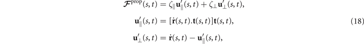
We perform PCA to describe the time-dependent shape deformation of isolated axonemes [16, 34]. This analysis is based on the method introduced by Stephens et al [34], which was initially used to characterize waveforms in C. elegans. Using the x and y coordinates of the tracked flagellum (see section 4.2), we calculate θ(s, t), which is defined as the angle between the local tangent vector of the centerline of the tracked flagellum and the -axis (see figure 1(A)). We recall that we chose the basal end (s = 0) at the origin (0, 0), with the tangent vector at s = 0 along the x-axis (figure 2(A)). We then average the axonemal shapes over one beat cycle to obtain the mean shape of the axoneme ⟨θ(s,t)⟩t , which corresponds to the arc-shaped filament colored in cyan in figure 2(A).

Next, we compute the covariance matrix θCov(s, s') of the fluctuations of the mean-subtracted angle θ(s, t) − ⟨θ(s,t)⟩t . Figure 3(A) shows the color map of the flagellum covariance matrix, which has an effective reduced dimensionality with a small number of non-zero eigenvalues. We note that four eigenmodes Mn (s) (n = 1, ..., 4) corresponding to the first four largest eigenvalues of θCov(s, s') capture the shape of the flagellum with very high accuracy (see video 2). These four eigenvectors are plotted in figure 3(B). We reconstruct the axonemal shapes using the four dominant modes and the corresponding time-dependent motion amplitudes an (t) as:

The reconstructed axonemal shapes are presented in figure 3(C), where the green dashed lines show the experimental data. The time-dependent coefficients a1(t) and a2(t) are shown in figure 3(D) (a3(t) and a4(t) are shown in figures S3 and S4). In order to compare the experimental data with the reconstructed shapes, figures 3(E) and (F) shows two exemplary configurations with the lowest and the highest root mean square errors of 0.006 and 0.085, respectively.

Figure 3. PCA analysis of the axoneme in figure 1. (A) The covariance matrix θCov(s, s') of fluctuations in θ(s, t) − ⟨θ(s,t)⟩t . (B) Four eigenvectors corresponding to the four largest eigenvalues of θCov(s, s'). (C) The time-projection of the mean-shape subtracted experimental data and the corresponding shapes reconstructed using the four eigenmodes presented in panel (B). (D) The time-dependent coefficients a1(t) and a2(t) as defined in equation (1). The cyan dashed lines present the Fourier fits as defined in equation (4). (E) and (F) To compare the experimental data with the reconstructed shapes, two exemplary configurations with the lowest and highest root mean square (RMS) errors are presented. (G) The fraction of the total variance plotted versus the number of PCA modes n. The figure in the inset illustrates one- versus n on a semi-log scale. See section 4.3 for the definition of . Note that two modes already capture 98.52% of the total variance and four modes capture 99.85%.


Download figure:
Standard image High-resolution imageLet us focus on the first two modes M1(s) and M2(s), which in combination with the first two time-dependent motion amplitudes a1(t) and a2(t) capture 98.52% of the total variance (figure 3(G)). The black dashed lines in figure 3(B) represent the Fourier fits of the modes, imposing the boundary condition θ(s = 0, t) = 0:


where k = 2π/λ and the parameters are: λ = 16.87 μm, b1 = 0.136, b2 = −0.055, c1 = 2.3 × 10⁻⁵, c2 = −0.239, c3 = 0.003, c4 = 0.061, c5 = 0.011, and c6 = 0.012. In addition, the cyan dashed lines in figure 3(D) fitting the time-dependent coefficients a1(t) and a2(t) in equation (1) are given by the Fourier modes as:

with the coefficients a11 = 5.29, a12 = −1.67, a21 = 0.78, a22 = 2.81 and ω0 = 2πf0 = 114.17 ± 0.06 rad s−1. Since the mean-shape ⟨θ(s,t)⟩t is subtracted, the time-average of both a1(t) and a2(t) is zero. Moreover, we note that, as shown in reference [16], the second harmonic can play a crucial role in the rotational speed of the axonemes, but at the level of our approximations, equation (4) provides a reasonable fit (see figure 3(D)). The spatial Fourier decomposition of the modes M1(s) and M2(s), as presented in equations (2) and (3), in combination with the time-dependent coefficients a1(t) and a2(t) in equation (4) describes the axonemal shapes with good accuracy, therefore the representation proposed here also accurately capture the boundary conditions at s = L. At the distal region of the axoneme, both θ(s = L, t) and its derivative oscillate at the beat frequency f0, as shown in figure S5.
Having described the angle θ(s, t) in terms of the eigenmodes M1(s) and M2(s), we calculate next the curvature waves as:

The mean angle ⟨θ(s,t)⟩t shows a linear trend with contour length s, indicating a constant static curvature κ0 (cyan filament in figure 2(A)). Next, we define the dimensionless curvature as C = κλ/(2π) and use equations (2)–(4) to express the deviation of C(s, t) from its averaged value C0 as a sum of propagating waves of wavenumber mk propagating forward and backward, respectively, with an amplitude Cm and . The expressions for Cm and can be readily derived from equations (2)–(4), and the resulting explicit expressions are given in the supplementary material (table S1). Interestingly, combining the Fourier decomposition in space of M1 (equation (2)) or M2 (equation (3)) with the temporal dependence of a1 or a2 (equation (4)) results in standing waves. Specifically, only M2 contributes to standing waves of wavenumbers 2k and 3k, resulting in and . On the other hand, both M1 and M2 generate a standing wave at wavenumber k, which implies that the coefficients . The expression for the spatial and temporal dependence of the curvature can then be arranged as:


where C0(s) = κ0(s)λ/(2π) is the dimensionless mean-curvature, κ0 is the mean curvature of the cyan filament in figure 2(A). For our exemplary axoneme in figure 1, the values of these coefficients are listed in the first row of table S2. For comparison, the extracted coefficients of five other free axonemes, all reactivated at [ATP] = 200 μM, are also presented.
We summarize some important properties of equation (6). (i) To reconstruct the axonemal shapes with high precision, in addition to the main spatial mode k, higher modes 2k and 3k, must be included. (ii) The Fourier analysis of the PCA modes shows that the main base-to-tip traveling wave component (with amplitude ) co-exists with standing waves at wavenumbers mk, with amplitudes . We note that these standing waves may result from modulations of the wave amplitude, as discussed in supplementary section S1.2. (iii) For the standing waves at wavenumber mk (m = 1, 2, 3) the waveform reduces to , with nodes at locations , n being an integer.


![${s}_{\text{node}}^{m}={(mk)}^{-1}[(2n+1)\pi /2-({\alpha }_{m}+{\alpha }_{m}^{\prime })/2]$](https://content.cld.iop.org/journals/1367-2630/24/5/053025/revision4/njpac688dieqn14.gif)
We stress that the representation of the wavy motion provided by equation (6) is only an approximation, and that deviations due to higher order PCA modes Mn with n > 2, among others, are expected to lead to for m = 2 and 3. Still, given that the two modes considered here account for of the total variance of the signal, the corrections to equation (6) are expected to be small. We also insist that the biological implications of describing the motion in terms of a dominant base-to-tip propagating wave, modulated by a set of standing waves remain to be discussed.


To distinguish the role of different modes in reconstructing the axonemal shapes, we compared the original experimental data (without the mean-shape subtraction) with the shapes reconstructed using the combination of different modes as . Please note that the time-average of is not zero and gives the axonemal mean-shape (cyan filament in figure 2(A)). The coefficients and ai are related by the simple relation . This comparison for different number of modes is presented in figure 4.
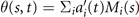


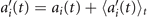

Figure 4. Experimental shapes over one beat cycle are compared with the free axonemal shapes, shown in figure 1, reconstructed using combinations of the PCA modes, , as discussed in the text. For each panel, the fraction of total variance is calculated; see section 4.3 for the definition of . Please note that in contrast to figure 3(C), the mean axonemal shape (cyan filament in figure 2(A)) is not subtracted.


Download figure:
Standard image High-resolution imageOur PCA analysis was applied to 20 different axonemes. The corresponding eigenmodes exhibit some similar trends, as can be seen by superposing them after re-scaling the contour length s by the total length L or the wavelength λ (see figures S6–S8).
2.3. Implication for the motion of free axonemes: an analytical study
To understand the effect of various modes on the rotational and translational velocities of a freely beating axoneme, we analyzed analytically a simplified waveform. For this purpose, we set the Fourier coefficients c3, c4, c5 and c6 in equation (3) to zero. These coefficients capture the effect of the higher spatial modes 2k and 3k. The green line in figure S9 shows the deviation between the experimentally extracted mode M2(s) and the corresponding fitted mode. We note that setting these coefficients to zero results to C'2=C'3=0 in equation (6), which leads to the simplified expression:

The total force and torque exerted on a freely swimming axoneme at low Reynolds number regime is zero. Given the prescribed form of curvature waves in equation (7), we used resistive force theory (RFT) [47, 48] to calculate propulsive forces and torques from the tangential and normal velocity components of each axonemal segment (see section 4.4). By imposing the force-free and torque-free constrains in 2D, we can uniquely determine the translational and rotational velocities of the axoneme. The resulting expressions for the translational and angular velocities, equations (S.3)–(S.5), reflect an important symmetry property of the system. Namely, for the axoneme to rotate, it is necessary to break the mirror symmetry, i.e. C0 ≠ 0. If the wave pattern of the axoneme is transformed to its mirror-image after half a period (i.e. C(s, t) = −C(s, t + T/2)), then the flagella will swim on average in a straight trajectory. This is the case if C0 = 0 in equation (7). The reason is that the mean rotations achieved in the first and second half-periods, have the same magnitude but opposite signs and the net rotation sums up to zero. Equations (S.3)–(S.5) also show that in the absence of even harmonics, ⟨Uy ⟩ = 0 and ⟨Ux ⟩ depends on the square of C1 and [46, 49, 50]. One notices that in the case of standing waves, , the net propulsion vanishes. Finally, in the case of λ = L and with the value of η−1 = ζ⊥/ζ∥ = 1.8 [48], equations (S.3)–(S.5) simplify to [20]:


2.4. Calcium reduces the static curvature of the axonemes
To investigate the effect of calcium ions on the flagellar waveform, we performed experiments at different calcium concentrations and systematically measured the static and dynamic components of the axonemal waveform. As shown in figure 5, we changed the calcium concentration from 10−4 mM to 1 mM and quantified the curvature waves of the reactivated axonemes. Our analysis confirms that the static component of the curvature waves C0 decreases by , as we increase [Ca2+] from 10−4 mM to 1 mM. The drop is relatively sharp at [Ca2+] around 0.02 mM, as shown in figure 5(A). This decrease in C0 causes a transition from a circular swimming trajectory to a straight trajectory (see figures 5(A) and (B) and video 3), as expected based on equation (S.3). We also observed that the beat frequency of axonemes drops slightly at high calcium concentrations around 1 mM (figure 5(C)). In addition, calcium ions affect the amplitude of the main traveling wave component. To quantify this effect, we examined the wave amplitudes C1 inferred from our PCA analysis. These results, which are plotted in figure 5(D), show a small decrease in C1 at high [Ca2+].


Figure 5. Experiments with free axonemes reactivated with the calcium-supplemented buffer at different calcium concentrations. (A) The static curvature C0 show a sudden drop from 0.3 to 0.05 at [Ca2+] around 0.02 mM which induces a switch from circular to straight swimming path. (B) Mean rotational velocity of axonemes decreases at [Ca2+] above 0.02 mM, consistent with the observation that axonemes switch from circular to straight swimming trajectories. (C) Beat frequency of axonemes drops slightly at [Ca2+] around 1 mM. (D) The wave amplitude C1 decreases slightly with [Ca2+]. In all the experiments, the ATP concentration is kept fixed at 200 μM.
Download figure:
Standard image High-resolution imageWe notice that calcium concentrations lower than ∼0.02 mM do not qualitatively affect the picture drawn in the absence of calcium, as summarized in section 2.1. However, at high calcium concentrations, the rotational velocities of axonemes Ωz (t) are small and highly noisy, and a direct measurement of ⟨Ωz ⟩ is difficult. Therefore, in figure 5(B), ⟨Ωz ⟩ are calculated using the full experimental shapes based on RFT simulations with η−1 = ζ⊥/ζ∥ ∼ 1.8. To check the validity of RFT in our system, we used our experimental data at zero or very low concentrations of calcium, where axonemes swim on circular paths and a direct measurement of ⟨Ωz ⟩ is possible. The comparison between the experimental measurements and RFT simulations is shown in figure 6(A). The black dashed line has the slope of 1 and passes through the origin, which provides a strong evidence for the validity of RFT in our experimental system. Furthermore, with respect to our PCA analysis discussed earlier, we mention that the mean axonemal rotational velocity determined with RFT depends on the number of modes considered for the shape reconstruction. Figure 6(B) shows that ⟨Ωz ⟩/ω0 converges for n ⩾ 4. The black dashed lines in figure 6(B) are the values of obtained using full experimental shapes, i.e. infinite number of modes.


Figure 6. (A) Comparison of the experimental rotational velocities of free axonemes with the corresponding values obtained by RFT simulations with full experimental shapes, i.e. infinite number of modes. The black line has the slope of 1 and passes through the origin. Each data point corresponds to one axoneme at a given calcium concentration. Circles show the data points which are used in panel (B). (B) The dependence of on the number of PCA modes considered for the shape reconstructions for the six axonemes, indicated by colored circles in panel (A).

Download figure:
Standard image High-resolution imageFinally, similar to figure 4, we performed PCA analysis to reconstruct axonemal shapes for an exemplary axoneme at calcium concentration of 0.1 mM. As shown in figure 7, the first four modes recapitulate the beat pattern of the axoneme with high accuracy.

Figure 7. Experimental shapes and different combinations of the four dominant eigenmodes used to reconstruct the axonemal shapes. For each panel, fraction of total variance is calculated. We note that the reconstructed pattern with 4 modes (second panel) captures 99.8% of the total variance. Here [ATP] = 0.2 mM and [Ca2+] = 0.1 mM.

Download figure:
Standard image High-resolution image2.5. Hinged and clamped boundary conditions
In our experiments, attachment of axonemes to the substrate occurred either from the basal end or the distal tip due to the non-specific axoneme-substrate interactions. These axonemes were either hinged from the basal or the distal side and rotated freely around the hinging point, as shown in figure 8 and videos 4–6, or they were clamped from the either side to the substrate and were unable to rotate, as shown in figure 9 and videos 7–10.

Figure 8. Hinged boundary condition. (A)–(C) A basal-hinged axoneme with the beat frequency of 44.34 ± 0.02 Hz rotates counter-clockwise around the pinning point while the bending waves propagate from the basal toward the distal tip (see video 4). The wavelength is 14.15 μm, the mean curvature κ0 = −0.17 μm−1, [ATP] = 200 μM and [Ca2+] = 0. The table in the white color shows that the amplitude of the base-to-tip traveling wave (C1) is around five times larger than the backward tip-to-base traveling wave (). (D)–(F) A distal-hinged axoneme with f0 = 55.65 ± 0.05 Hz rotates CW around the pinning point (see videos 5 and 6). The parameters are: κ0 = −0.19 μm−1, [ATP] = 1 mM and [Ca2+] = 0. In this case, C1 is almost six times larger than , which is comparable to the basal-hinged axoneme; see table S3.


Download figure:
Standard image High-resolution image
Figure 9. Clamped boundary condition. (A) A clamped axoneme attached firmly from the basal region to the substrate. (B) Time-projection of the axonemal shapes in the time interval of 500 ms. Note that only the oscillating part of the axonemal length (∼7 μm) is included in this image. The thick white line highlights the position of the surface-attached segment of the axoneme. (C) Curvature waves propagating at the frequency of f0 = 20.31 ± 0.29 Hz from the clamped region toward the distal tip. The mean curvature of axoneme is κ0 ∼ −0.05 μm−1. (D)–(F) Similar to the panels (A)–(C) with the important difference that the axoneme is clamped from the distal tip. This axoneme has a higher wave amplitude C1 (see table S3), and it beats at f0 = 30.73 ± 0.06 Hz with a mean curvature of κ0 ∼ −0.18 μm−1. For both experiments [ATP] = 80 μM and [Ca2+] = 0; see videos 7–10.
Download figure:
Standard image High-resolution imageLet us first focus on the hinged boundary condition and consider an exemplary case where the axoneme is attached from the basal end and rotates counter-clockwise at the mean rotational velocity of ⟨Ωz ⟩ ∼ 15 rad s−1 around the pinning point (figures 8(A) and (B)). Curvature waves initiate at the surface-attached proximal region (s = 0) and travel at the frequency of 44.34 ± 0.02 Hz toward the distal tip (s = L); see figure 8(C). This axoneme has an intrinsic curvature of ∼−0.17 μm−1, which is comparable to the corresponding value for the free axoneme presented in figure 1. The amplitude of the traveling wave components, which are inferred from the PCA analysis, are listed in the top panel of table S3 (shapes reconstructed from the PCA analysis are illustrated in figure S10). Comparison of the wave amplitudes shows that the main wave amplitude C1 is almost 5 times larger than the wave component ; see also table S4 for wave amplitudes of two other basal-hinged exemplary axonemes. For comparison, we also present a distal-hinged axoneme which rotates clockwise around the hinging point, as shown in figures 8(D)–(F). The hinging of axonemes from the distal tip to the substrate rarely occurred in our experiments. For this exemplary case, C1 and extracted from the PCA analysis show that (see the second panel of table S3), which is comparable with the values obtained for the basal-hinged axoneme in panels (A)–(C).


To calculate the mean rotational velocity of a model hinged axoneme, we used RFT and the simplified waveform given by equation (7). As noted above, a hinged axoneme was free to rotate but not to translate, thus the total torque exerted on the axoneme is zero while the total force is non-zero. Following the procedure outlined in section 4.5, we calculate the mean rotational velocity of the axoneme up to the first order in C0 and second order in C1 and we arrive at equation (S.6), where in the limit of λ = L and with η−1 = ζ⊥/ζ∥ = 1.8, it further simplifies to


Comparison with the pre-factor in equation (8) shows that with the same intrinsic curvature C0 and wave amplitudes C1 and , the hinged axoneme rotates on average slower than a free one.

Finally, we present the experimental data of two exemplary non-rotating clamped axonemes where part of the axonemal length, either at the basal or the distal tip, was firmly attached to the substrate. Figures 9(A)–(C) shows a basal-clamped axoneme that beats at the frequency of f0 = 20.31 ± 0.29 Hz with a reduced intrinsic curvature κ0 ∼ −0.05 μm−1, compared to the free and hinged axonemes. The amplitude of the main traveling wave component C1, extracted form PCA analysis is also reduced compared to the free and hinged axonemes. Moreover, the amplitude of the standing wave is three times smaller than the main base-to-tip propagating wave component C1 (see the third panel of table S3). Notably, for the case where the axoneme is clamped from the distal tip, the magnitude of the standing wave component becomes larger , indicating possible wave reflection from the clamped side of the axoneme (see figures 9(D)–(F) and the forth panel of table S3). In intact C. reinhardtii cells, the attachment of the flagellum to the cell body is close to a basal-clamped boundary condition, so we repeated our PCA analysis for a flagellum in an intact cell (see figures S1(A) and (B) and S11). This analysis gives , which is comparable to the values mentioned above for the basal-clamped isolated axonemes.


3. Discussion
In this work, we have isolated flagella from green algae C. reinhardtii and removed the membrane by treatment of detached flagella with non-ionic detergents [8, 36]. The remaining structure, without membrane and basal bodies, can be reactivated by an ATP-supplemented buffer. Active axonemes show an asymmetric waveform predominantly in 2D, which mostly resembles the forward swimming motion of flagella in intact cells [10, 12]. These asymmetrical beating patterns cause the axoneme to rotate stably around a position in the microscope's field of view. We extracted the shape of axonemes by GVF technique [41, 42] and quantitatively described the flagellar beating patterns by dimensionless local curvature C(s, t) at time t and arc-length s along the axonemal length. The results presented in this paper are focused on the examples where axonemes swim effectively in 2D in the vicinity of the substrate. However, we also observed examples where the axonemes swim in 3D and undergo tumbling motion, as shown in the supplemental video 11. This out of plane swimming dynamics complicates the tracking process of the axonemes. In future studies, 3D microscopy techniques [45, 51] are necessary to capture the full 3D swimming dynamics of the isolated axonemes.
The static component of the axonemal waveform, defined as the average angle over one beat cycle at each position along the axonemal length, highlights the existence of an intrinsic curvature of axonemes around the value of ∼−0.2 μm−1. To bend an axoneme to a circular arc, shear forces along the axonemal centerline generated by asymmetric distribution of dynein motors are required to induce a dynamic instability [19, 30, 31, 52, 53]. Among different dynein motors, IDAb (inner dynein arm b) is possibly the only dynein which has an asymmetric distribution, both radially and longitudinally. Bui et al [54] have shown that IDAb is absent in the proximal region without being replaced by another dynein, and is predominantly localized at the distal tip with a radially asymmetric distribution. The depletion of IDAb from the proximal area might suggest its specific function in bending the axoneme. Future experiments with IDAb mutants are necessary to investigate the possible role of IDAb in inducing an intrinsic curvature in axonemes.
In our experiments with calcium, we observed that among the modes constituting the flagellar waveform, the static component C0 is the most sensitive mode, decreasing significantly (∼10 times) at calcium concentrations above 0.02 mM. The main traveling wave component C1 is also calcium-sensitive, especially at high calcium concentrations around 1 mM where C1 decreases with a factor of less than two. The reduction of the static mode triggers a switch from circular to straight swimming path, as previously observed in references [22, 23]. Based on high-resolution structural information obtained by electron cryotomography, Gui et al [55] have proposed that RS (radial spoke) heads and CP (central pair) projections interact via electrostatic forces. In this model, an increase in the electrostatic force with decreasing distance as the axoneme bends causes a tilt of the radial spoke. This tilt is the mechanosignal that is transmitted to the IDAs (inner dynein arms), the N-DRC (nexin-dynein regulatory complex) and, finally, to the ODAs (outer dynein arms). These electron cryotomography data support the idea that calcium may regulate the transmission of these mechanosignals by inducing a conformational change in calmodulin, which is a calcium responsive protein at the interface between RS1 (radial spoke 1) and IDAa (inner dynein arm a; see figure S1). This conformational change in calmodulin can alter directly the wave pattern by affecting RS1-IDAa interaction. An alternative plausible mechanism is that calcium affects a calmodulin-like subunit (LC4) of the ODAs, and consequently influences the dynein behavior [56]. Further experiments are required to clarify the mechanism of dynein regulation and the precise role of calcium in shaping the flagellar waveform.
The Fourier analysis of the PCA modes in the cases of free, hinged and clamped axonemes shows that the leading traveling wave component coexists with standing waves at the wavelength of the leading mode and at higher spatial modes. Remarkably, applying the Fourier analysis to flagella of intact C. reinhardtii cells yields results (see figure S11) that are very similar to those presented here. As discussed in the supplementary section S1.2, the description in terms of a dominant propagation wave superimposed by standing waves does not lead to an immediate biological interpretation, and an alternative explanation for the observed wave patterns could be an arc-length dependent amplitude of axonemal bending waves. It would be interesting to see if our analysis leads to qualitatively similar results when applied to numerical solutions of simplified models of cilia [30, 32]. In these models, the dynein regulation mechanism affects the wave propagation direction: while in curvature-feedback mechanism [57–59], there is an inherent direction in wave propagation which is determined by the coupling between molecular motors and the local axonemal curvature [18, 60], in sliding-control mechanisms wave direction is not fixed intrinsically, but strongly depends on the boundary condition. This mechanism can be described by considering a model axoneme composed of two polar elastic filaments coupled by passive cross-linkers, and dynein motors exert sliding forces in opposite direction on the two facing filaments, generating an active stress along the long axis of the filament. The unbinding of dynein motors is controlled by the sliding motion between the neighboring microtubule doublets [18, 60–62]. As the motor activity increases, a Hopf bifurcation leading to sustained oscillations is observed. As mentioned above, the direction of deformation waves depends on the boundary conditions: for hinged filaments, the waves propagate from base-to-tip while for clamped boundary conditions, the waves propagate in the opposite direction. At higher motor activity, a second bifurcation occurs and non-linearities cause a reversal in the direction of wave propagation [30, 32]. This transition from tip-to-base to base-to-tip wave propagation occurs through a narrow transitional region of intermediate states [33]. The wave dynamics in the corresponding intermediate regime is reported to be chaotic and is a superposition of standing waves with waves switching quasi-periodically their direction of propagation [33].
Moreover, the analysis by Camalet et al [19, 29] shows that in an internally-driven filament, with a coarse-grained oscillatory force density acting in opposite directions tangentially on two filaments, traveling wave solution can be induced via a dynamic instability. The resulting wave patterns do not depend on the microscopic mechanism of the instability but only of the hydrodynamic forces and the filament rigidity. In this approach, which rests on a coarse-graining of the molecular motors, the direction of wave propagation also depends critically on the boundary condition. Lastly, we note that other approximations, such as time-delay variations of the contractile tensions also lead to spontaneous oscillations of the filament [63, 64], although a non-linear relation between length variation and tension is needed to keep the wave amplitude finite. For such a non-linear response, the traveling wave can exist only in one direction and a traveling wave solution in both directions is an unstable solution [63, 64]. In this context, it is interesting to emphasize that the Fourier analysis of the PCA modes of our experimental results shows that the nature of the standing waves is not qualitatively affected by the boundary conditions. To explain this striking difference, one could hypothesize that the discrete structure of the axoneme at the microscopic level, as shown in figures S1(C) and (D), leads to significant deviations at the macroscopic level, especially by changing the boundary conditions at both ends of the cilium. In future studies, it would be an interesting challenge to attribute the formation of these standing waves to the underlying biology and to understand the contribution of different molecular dynein motors in the formation of the standing waves, as well as to determine the mechanism of dynein regulation in cilia and flagella.
4. Materials and methods
4.1. Isolation of axonemes from C. reinhardtii
We used wild-type C. reinhardtii cells, strain SAG 11-32b, to isolate flagella using dibucaine following the protocols in references [36, 65]. First, we grew the cells axenically in TAP (tris-acetate-phosphate) medium on a 12 h/12 h day–night cycle. Cells release their flagella upon adding dibucaine, which we purify on a 25% sucrose cushion, and demembranate using detergent NP-40 in HMDEK solution (30 mM HEPES-KOH, 5 mM MgSO4, 1 mM DTT, 1 mM EGTA, 50 mM potassium acetate, pH 7.4) supplemented with 0.2 mM Pefabloc. The membrane-free axonemes were resuspended in HMDEK buffer plus 1% (w/v) polyethylene glycol (Mw = 20 kg mol−1), 0.2 mM Pefabloc and used freshly after isolation. To perform reactivation experiments, we diluted axonemes in HMDEKP reactivation buffer (HMDEK plus 1% PEG) supplemented with 0.2 mM Pefabloc and different concentrations of ATP. Reactivation solution plus axonemes was infused into 100 μm deep flow chambers, built from cleaned glass and double-sided tape. To avoid axoneme attachment to the substrate, glass slides are coated with 2 mg mL−1 casein solved in HMDEKP. For calcium experiments, HMDEKP reactivation buffer is supplemented with calcium at different concentrations.
4.2. Axoneme tracking
We used high-frame phase-contrast microscopy to analyze fast beating dynamics of axonemes (100× objective, 1000 fps). First, we inverted phase-contrast images and subtracted the mean-intensity of the time series to increase the signal to noise ratio [15]. Next, we applied a Gaussian filter to smooth the images. Tracking of axonemes is done using GVF technique [41, 42]. For the first frame, we select a region of interest that should contain only one actively beating axoneme (see figure S2). Then, we initialize the snake by drawing a line polygon along the contour of the axoneme in the first frame. This polygon is interpolated at N equally spaced points and used as a starting parameter for the snake. The GVF is calculated using the GVF regularization coefficient μ = 0.1, as defined in equation (10) of reference [41], with 20 iterations. The snake is then deformed according to the GVF where we have adapted the original algorithm by Xu and Prince for open boundary conditions [41, 42]. We obtain positions of N points along the contour length s of the filament so that s = 0 is the basal end and s = L is the distal side, where L is the total contour length of filament. The position of filament at si is denoted by r (si ) = (x(si ), y(si )).
4.3. Principal component analysis
We describe the shape of each flagellum by its unit tangent vector and the unit normal vector at distance s along the contour [66, 67]. Instantaneous deformation of flagellum is described by curvature κ(s, t), which using Frenet–Serret formulas is given by [34]


Let us define θ(s) to be the angle between the tangent vector at distance s and the x-axis, then κ(s) = dθ(s)/ds. For shape analysis, we translate and rotate each flagellum such that basal end is at (0, 0) and the orientation of the tangent vector at s = 0 is along the -axis i.e. θ(s = 0, t) = 0. Following Stephens et al [34], we performed PCA by calculating the covariance matrix of mean-subtracted angles θm (s, t) = θ(s, t) − ⟨θ(s,t)⟩t , defined as θCov(s, s') = ⟨(θm (s, t) − ⟨θm ⟩)(θm (s', t) − ⟨θm ⟩)⟩, where ⟨θm ⟩ is the spatial average of θm (s, t) at a given time t. The eigenvalues λn and the corresponding eigenvectors Mn (s) of the covariance matrix are given by Σs' θCov(s, s')Mn (s') = λn (t)Mn (s). Figure 3 shows that the superposition of four eigenvectors corresponding to the four largest eigenvalues can describe the flagellum shape with high accuracy:


Here the four variables a1(t), ..., a4(t) are the amplitudes of motion along different principal components and are given by an (t) = ∑s Mn (s)θm (s, t). The fractional variance of flagellum's shape captured by n eigenvectors is calculated as where . Here N is the total number of eigenvectors. Figure 3(G) shows that already two modes capture 98.52% and four modes capture 99.85% of the total variance.

4.4. Resistive force theory and calculations of the mean translational and rotational velocities of a free axoneme
Biological microorganisms swim with flagella and cilia in the world of 'low Reynolds number' where they experience viscous forces many orders of magnitude larger than inertial forces [44, 68]. In this world where inertia is negligible, Newton's law becomes an instantaneous balance between external and fluid forces and torques exerted on the swimmer, i.e. and . The force and torque exerted by the fluid on the axoneme can be written as


where the integrals over the contour length L of the axoneme calculate the total hydrodynamic force and torque exerted by the fluid on the axoneme. ATP-reactivated axonemes show oscillatory shape deformations. At any given time, we consider an axoneme as a solid body with unknown translational and rotational velocities U(t) and Ω(t), yet to be determined. and can be separated into propulsive part due to the relative shape deformation of the axoneme in the body-fixed frame and the drag part [69]


where 6 × 6 geometry-dependent drag matrix of the axoneme is symmetric and nonsingular (invertible). We also note that a freely swimming axoneme experiences no external forces and torques, thus and must vanish. Further, since swimming effectively occurs in 2D, is reduced to a 3 × 3 matrix and equation (16) can be reformulated as


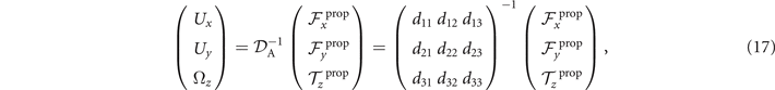
which we use to calculate translational and rotational velocities of the swimmer after determining the drag matrices and the propulsive forces and torque .

We calculate , and which are propulsive forces and torque due to the shape deformations of the axoneme in the swimmer-fixed frame by selecting the basal end of the axoneme as the origin of the swimmer-fixed frame. As shown in figure 1(A), we define the local tangent vector at contour length s = 0 as direction, the local normal vector as direction, and assume that and are parallel. Let us define θ0(t) = θ(s = 0, t) as the angle between and which gives the velocity of the basal end in the laboratory frame as and . Furthermore, we note that the instantaneous velocity of the axoneme in the lab frame is given by u = U + Ω × r(s, t) + u', where u' is the deformation velocity of flagella in the swimmer-fixed frame, U = (Ux , Uy , 0) and Ω = (0, 0, Ωz ) with Ωz = dθ0(t)/dt.


To calculate , and for a given beating pattern of axoneme in the body-fixed frame, we used classical framework of RFT which neglects long-range hydrodynamic interactions between different parts of the axoneme [47, 48]. In this theory, axoneme is divided into small cylindrical segments moving with velocity u'(s, t) in the body-frame and propulsive force is proportional to the local centerline velocity components of each segment in parallel and perpendicular directions


where and are the projections of the local velocity on the directions parallel and perpendicular to the axoneme. The friction coefficients in parallel and perpendicular directions are defined as ζ∥ = 4πμ/(ln(2L/a) + 0.5) and ζ⊥ = 2ζ∥, respectively. This anisotropy indicates that to obtain the same velocity, one would need to apply a force in the perpendicular direction twice as large as that in the parallel direction [47, 48]. Axoneme is a filament of length L ∼ 10 μm and radius a ∼ 100 nm. For a water-like environment with viscosity μ = 0.96 pN ms μm− 2, we obtain ζ∥ ∼ 2.1 pN ms μm− 2.


4.5. Approximation of the mean rotational velocity of a hinged axoneme
Consider an axoneme which is attached from the basal end to the substrate and rotates around the hinging point (see figure 8(A)). We select the hinging point of the axoneme as the origin of the swimmer-fixed frame, and define tangent and normal vectors at s = 0 as the coordinate system in the swimmer-fixed frame. Since the axoneme is free to rotate but not to translate, the total torque exerted on the axoneme is zero but the total force and is non-zero. Reformulating in terms of equation (16), we have


which by imposing the constrains of Ux = 0, Uy = 0 and simplifies to


Using this equation, we can calculate the instantaneous rotational velocity of a hinged axoneme as

where

Here f(s, t) is calculated using equation (18) based on the simplified waveform defined in equation (7).
To calculate mean rotational velocity for a hinged axoneme, we average over one beat cycle

Please note that for a clamped boundary condition, since the mean translational and rotational velocities of the axoneme are zero, the total torque and the total force ( and ) are non-zero, and are equal to the propulsive force and torque


Acknowledgments
The authors are grateful to A Krekhov, V Geyer, G Gompper, J Elgeti, J Molacek, and F Nordsiek for valuable comments, S Goli Pozveh and Y Su for their support and S Romanowsky, M Müller and K Gunkel for technical assistance, and to anonymous referees for providing important insight. The authors acknowledge the Volkswagen Foundation Initiative LIFE (Project Living Foam) and the MaxSynBio Consortium, which is jointly funded by the Federal Ministry of Education and Research of Germany and the Max Planck Society. R.A. acknowledges support from the European Union's Horizon 2020 research and innovation programme under Grant Agreement MAMI No. 766007. The authors also thank M Lorenz and S Bank at the Göttingen Algae Culture Collection (SAG) for providing the C. reinhardtii wild type strain SAG 11-32b.
Data availability statement
The data that support the findings of this study are openly available at the following URL/DOI: 10.5281/zenodo.6406759.