


Abstract
Particle accelerator on chip with high acceleration gradient has been an unremitting goal of researchers. Dielectric laser accelerator (DLA) is a possible candidate to achieve this goal. However, due to the limitation of dielectric breakdown, it is difficult for the available DLAs to reach an acceleration gradient as high as 1 GV m−1 since a long-duration multi-cycle laser pulse with high fluence have to be used. Here we propose to use a few-cycle laser pulse to drive a DLA based on the inverse Cherekov radiation effect. It significantly reduces the required pulse duration and the laser fluence, remarkably increasing the achievable acceleration gradient. Moreover, by using a cascade acceleration scheme, we realize a high energy-gain acceleration for low-energy electrons in a microscale device by simulation, which paves the way for the development of a fully on-chip particle accelerator.
Export citation and abstract BibTeX RIS

Original content from this work may be used under the terms of the Creative Commons Attribution 4.0 licence. Any further distribution of this work must maintain attribution to the author(s) and the title of the work, journal citation and DOI.
1. Introduction
The development of on-chip particle accelerators with high acceleration gradients has been a goal of researchers during the past decades [1–5], and yet it is still a challenge. Dielectric laser accelerator (DLA), which uses high-power laser pulses to drive microscale dielectric mediums [6–9], is a possible candidate to achieve this goal [10]. The acceleration capability of DLA is essentially restricted by the laser-induced breakdown and the nonlinear effect of dielectric material [11–14]. In physics, laser power and pulse duration jointly contribute to breakdown. They have opposite effects in determining the achievable acceleration gradient: a long pulse duration leads to a low acceleration gradient [15]. In the previous DLA schemes based on the inverse Smith–Purcell effect (ISP-DLA), the electron bunch interacts with the longitudinally modulated fields of a transverse propagation driving laser. It has to experience multi-cycles of laser fields in order to get a long-range acceleration [16–18], such that a long-duration laser pulse has to be adopted, which restricts the achievable acceleration gradient.
Recently, using the evanescent waves induced by the total internal reflection of light at a flat dielectric surface to modulate and accelerate charge particles was investigated theoretically [19] and experimentally [20, 21]. This kind of particle accelerator was found to be based on the inverse effect of the famous Cherenkov radiation (CR) (hereinafter referred to as ICR-DLA) [22], which can be readily realized by using a laser beam to drive a dielectric prism. Compared with ISP-DLA, which resorts to nanoscale periodic structures, ICR-DLA based on a microscale dielectric prism is easier to manufacture and also has higher breakdown threshold in practice. In addition, the particles in ICR-DLA are synchronized with the laser field without using external pulse-front tilting technique, which is indispensable in ISP-DLA. So far, however, a series of critical issues which are important for the practical applications of ICR-DLA, including wakefield radiation, pulse fluence, and the acceleration of low-energy particles [23–25], had not been investigated in detail.
In the present paper, we propose to use a few-cycle laser pulse to drive ICR-DLA. Compared with previous DLAs, the required pulse duration is reduced by several orders of magnitude, such that the laser power and the achievable acceleration gradient can be significantly improved without causing breakdown [26]. Wakefield radiation is taken into consideration and the bunch charge is optimized to balance radiation loss and acceleration. In addition, we use two symmetric prisms to counteract the particle deflection, which is serious in the subrelativistic or low-energy region. Moreover, we propose a cascade acceleration scheme to realize a high energy gain acceleration for low-energy particles in a microscale device, which paves the way for the development of a fully on-chip particle accelerator.
2. Model description
A schematic diagram of the proposed scheme is shown in figure 1, which utilizes a linearly polarized laser pulse to vertically incident on the right angle surface of a dielectric prism with a right triangle cross section. The incoming free electrons move parallel to the hypotenuse surface of the prism (in the z direction). The laser pulse penetrates the prism and then launches an evanescent wave along the hypotenuse surface with phase velocity vp = c/(n cos θ) [27], in which c is the speed of light in vacuum, n the refractive index of the prism, and θ the incident angle of the laser pulse on the hypotenuse surface. When the phase velocity vp matches the electron velocity ve, the longitudinal electric fields of the evanescent waves, which are essentially transverse magnetic waves rather than transverse electromagnetic (TEM) waves, will provide the electron bunch with a continuous longitudinal force, decelerating or accelerating it depending on the synchronization phase. The transverse field components of the evanescent wave (Ex and Hy ) may deflect the electrons towards or away from the prism. Calculations show that, for relativistic electrons (with ve/c = β ≈ 1), the deflection forces exerted by Ex and by Hy will largely cancel each other out since they are almost equal in magnitude and opposite in direction [22]. While for low-energy (subrelativistic) electrons (with β < 1), the electric and magnetic deflection forces cannot cancel each other out, so as that the electrons will experience serious deflection while accelerating [28], which is we mainly deal with in the present paper.
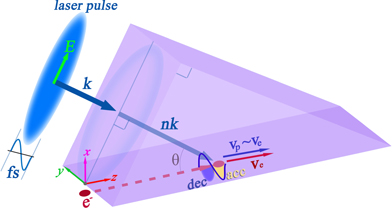
Figure 1. A simplified schematic of ICR-DLA. The acceleration (acc) and deceleration (dec) regions of the laser pulse are illustrated in yellow and in blue, respectively.
Download figure:
Standard image High-resolution imageSimulations are performed by using a two-dimensional particle-in-cell (PIC) code [29], in which wakefield radiation and space-charge effect are both taken into account. The electric field of the incident laser pulse can be expressed as ![$E\left(t\right)={E}_{\mathrm{m}}{e}^{\left(-0.5{\left(\left(t-{t}_{0}\right)/\sigma \right)}^{2}\right)}\enspace \mathrm{sin}\left[2\pi {f}_{0}\left(t-{t}_{0}\right)\right]$](https://content.cld.iop.org/journals/1367-2630/23/6/063031/3/njpac03cfieqn1.gif) , in which Em denotes the field amplitude, σ the root-mean-square pulse-duration, t0 the time delay and f0 the central frequency. The simulated electric field of the laser pulse in the time domain detected on the dielectric surface is presented in figure 2(a), in which Em ≈ 6 GV m−1, σ = 5 fs, and f0 = 300 THz. Here we chose these values of f0 and σ, which is to show the applicability of a single-cycle femtosecond pulse in the proposed scheme, while knowing that the femtosecond laser pulses with other frequencies can also be used. The initial electron energy is set to 300 keV, being in the low-energy (β < 1) region. The prism is chosen as a high-breakdown-threshold quartz with refractive index n = 1.45 [30, 31] and the laser incident angle is θ = 56.4°, satisfying the synchronization condition mentioned above. A Gaussian electron bunch with full-width-at-half-maximum (FWHM) length of σb ≈ 2 fs is located in the acceleration half-period of the laser field as shown in figure 2(a). We note that the controllable attosecond-class electron bunches had been obtained in previous experience [32]. The charge quantity is about 23.5 fC per millimeter (in the y direction) and the initial emittance is set to
, in which Em denotes the field amplitude, σ the root-mean-square pulse-duration, t0 the time delay and f0 the central frequency. The simulated electric field of the laser pulse in the time domain detected on the dielectric surface is presented in figure 2(a), in which Em ≈ 6 GV m−1, σ = 5 fs, and f0 = 300 THz. Here we chose these values of f0 and σ, which is to show the applicability of a single-cycle femtosecond pulse in the proposed scheme, while knowing that the femtosecond laser pulses with other frequencies can also be used. The initial electron energy is set to 300 keV, being in the low-energy (β < 1) region. The prism is chosen as a high-breakdown-threshold quartz with refractive index n = 1.45 [30, 31] and the laser incident angle is θ = 56.4°, satisfying the synchronization condition mentioned above. A Gaussian electron bunch with full-width-at-half-maximum (FWHM) length of σb ≈ 2 fs is located in the acceleration half-period of the laser field as shown in figure 2(a). We note that the controllable attosecond-class electron bunches had been obtained in previous experience [32]. The charge quantity is about 23.5 fC per millimeter (in the y direction) and the initial emittance is set to  n
= 10−9 m rad. The initial transverse bunch size (in the x direction) is 0.2 μm and the initial bunch length (in the z direction) is 0.8 μm. The initial distance from the electron bunch to the prism surface is 0.4 μm. The propagating length of the electron bunch along the hypotenuse surface is 50 μm. The simulated snapshots of the bunch positions and of the laser pulse propagating in the prism are shown in figure 2(b), which indicates that the electron bunch is synchronized with the laser pulse as predicted. The electron energy versus the longitudinal position is illustrated in figure 2(c), which shows that the continuous acceleration is realized: the electron energy reaches about 380 keV after acceleration. The average acceleration gradient is about 1.6 GV m−1 (acceleration factor Eacc/Em is about 0.25). We note that the acceleration gradient decreases in the rear part of the channel, which can be explained that the synchronization requirement is no longer satisfied when the electron velocity is substantially increased after acceleration. In other words, the actual acceleration length is limited, which is a typical feature as accelerating low-energy particles. For comparison, the simulation result when the laser pulse is off is also presented in the figure. It shows that the energy of electrons decreases along the channel, which is due to the energy loss in the process of wakefield radiation as will be discussed.
n
= 10−9 m rad. The initial transverse bunch size (in the x direction) is 0.2 μm and the initial bunch length (in the z direction) is 0.8 μm. The initial distance from the electron bunch to the prism surface is 0.4 μm. The propagating length of the electron bunch along the hypotenuse surface is 50 μm. The simulated snapshots of the bunch positions and of the laser pulse propagating in the prism are shown in figure 2(b), which indicates that the electron bunch is synchronized with the laser pulse as predicted. The electron energy versus the longitudinal position is illustrated in figure 2(c), which shows that the continuous acceleration is realized: the electron energy reaches about 380 keV after acceleration. The average acceleration gradient is about 1.6 GV m−1 (acceleration factor Eacc/Em is about 0.25). We note that the acceleration gradient decreases in the rear part of the channel, which can be explained that the synchronization requirement is no longer satisfied when the electron velocity is substantially increased after acceleration. In other words, the actual acceleration length is limited, which is a typical feature as accelerating low-energy particles. For comparison, the simulation result when the laser pulse is off is also presented in the figure. It shows that the energy of electrons decreases along the channel, which is due to the energy loss in the process of wakefield radiation as will be discussed.

Figure 2. (a) The laser field and the bunch current in the time domain applied in simulations. (b) Simulated snapshots of the electron bunch (up) and of the laser field (down) at different instants of time. (c) Simulated electron energy of the bunch versus longitudinal position.
Download figure:
Standard image High-resolution imageIn order to accelerate the low-energy particles for a long distance with a high energy gain, two critical issues mentioned above, deflection and unsynchronization, have to be settled. To mitigate the electron deflection, we propose to use two identical laser pulses to drive two symmetric prisms, the schematic of which is shown in figure 3(a). As illustrated in the supplement (https://stacks.iop.org/NJP/23/063031/mmedia) [28], under this circumstance, the transverse forces at both sides of the center line of the bunch channel are equal in magnitude and opposite in direction, so as that the bunch deflection is avoided [33, 34]. In order to meet the synchronization requirement for a long distance, we propose to use a series of laser pulses to drive cascade sections of symmetric prisms, which is also shown in figure 3(a). The base angle of the prism in each section αi satisfies the relation of sin αi = c/[(ve + Δi )n] (i = 1, 2, ...), in which ve + Δi denotes the electron velocity after ith acceleration section, namely, it is the electron velocity at the entrance of the (i + 1)th acceleration section. In other words, a long acceleration range is divided into several short-length sections and the synchronization condition is approximately satisfied in each section. Note that the time delay of the laser pulse on each section should also be optimized [36]. Figure 3(b) shows the simulated snapshots of the laser field and of the electron bunch in the cascade scheme. Here three cascade acceleration sections are adopted and the results at three moments are combinedly presented. The angles of the prisms α1, α2, and α3 are set as 56.4°, 54.5°, and 50.9°, respectively. The lengths of three sections L1, L2, and L3 are all 50 μm. The width of the bunch channel in the x direction (the width of the gap between the two symmetric prisms), which should be largely equal to or less than the wavelength of the driven laser, is set to 1 μm. The parameters of the electron bunch follow that in figure 2. We note that the synchronizations between the electron bunch and the laser pulses are realized in all three sections as predicted. The simulated electron energy versus longitudinal position is presented in figure 3(c), which shows that the cascaded acceleration is realized and the average electron energy reach about 520 keV after the three-stage acceleration (the average acceleration gradient is about 1.5 GV m−1). Based on the above results, we envisage that, with the cascaded scheme, the sub-relativity to relativity acceleration can be realized from a millimeter-scale accelerator. Thus, the proposed scheme promises a fully on-chip particle accelerator.

Figure 3. (a) Schematic diagram of the proposed cascade acceleration scheme. (b) Simulated snapshots of the laser field and of the electron bunch at three instants of time. Here the results at three moments are jointly shown. The insets are the enlarged figures (in the same scale) of charge distributions. (c) Simulated electron energy versus longitudinal position. Here the lengths of three sections are all 50 μm and the width of the bunch channel is 1 μm.
Download figure:
Standard image High-resolution imageTo illustrate the evolution of the bunch size in the transverse direction, the simulated snapshots of the bunch distributions at different moments are jointly shown in figure 4, in which the results of the cascade single-prism model [figure 4(a)] and of the cascade double-prism model [figure 4(b)] are presented for comparison. As shown in figure 4(a), the bunch deflection in the single-prism case is remarkable, and the electron bunch hits the surface of the prism (x = 0) in the second acceleration section. In contrast, in the double-prism case, the electron bunch propagates straightly in the longitudinal (z) direction, namely, the bunch deflection is avoided. From the insets we notice that the electron bunch is compressed and defocused in the x direction, and is elongated in the z direction especially in the rear portion of the bunch channel. In other words, the bunch shape is deformed, which can be explained as follows. As mentioned above, the TEM forces exerted on the electron bunch are symmetrically distributed about the center line of the bunch channel which will compress or defocus the electron bunch in the x direction. In addition, since the electron bunch has a certain length, the electrons in the different positions of the bunch experience different phases of electromagnetic field, which will cause the electron bunch to stretch. In practice, more than three acceleration sections may be needed to realized high energy gain of accelerated particles, which may cause the bunch lengthening and defocusing to be more serious. We note that a series of methods had been proposed to counteract these effects, such as using an alternating phase focusing scheme [35], enabling a long-range acceleration with an acceptable bunch degeneration.
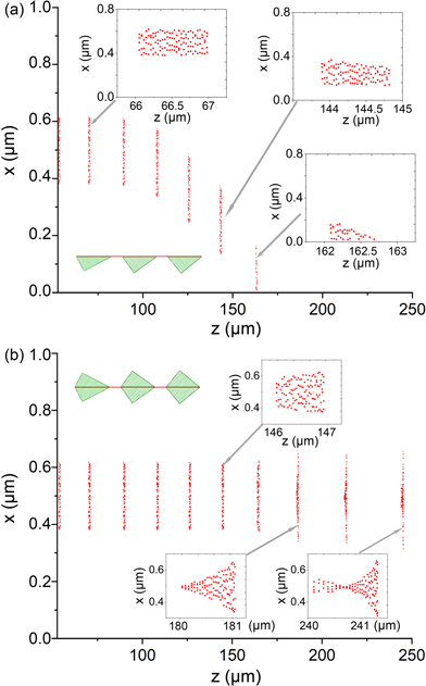
Figure 4. Simulated snapshots of the bunch distributions at different moments for the cases of (a) cascade single-prism and (b) cascade double-prism. The insets show the enlarged figures of bunch distributions. Here x = 0 denotes the position of dielectric surface in the single-prism case and x = 1 μm denotes another dielectric surface in the double-prism case.
Download figure:
Standard image High-resolution imageThe simulated acceleration gradient and beam emittance (after acceleration) as a function of bunch charge are shown in figure 5(a), in which the initial emittance is also presented. When the bunch charge is relatively low (less than 0.3 pC), the acceleration gradient keeps at about 1.5 GV m−1, and the final beam emittance is less than 50 nm rad, indicating that the scheme can normally operate. Note that the final emittance is much higher than the initial one, which is due to the nonuniform distribution of the evanescent fields in the bunch channel. Based on the simulated results, we can evaluate acceleration efficiency—the fraction of laser energy that has been transformed into the kinetic energy of electron bunch expressed by  , in which q is bunch charge, ΔE energy gain per unit charge, S the effective interaction area between the laser. Calculations show that the efficiency varies from 10−6 to 10−3 depending on the accelerated bunch charge. From the figure we can see that when the bunch charge is large enough, the acceleration gradient decreases and the emittance increases remarkably, see the case of 3 pC in the figure. Two factors may contribute to this: wakefield radiation and space-charge effect. According to previous studies [37, 38], the electron bunch will generate wakefield radiation in the prism, which is exactly the CR [39, 40], since the electron velocity is greater than the speed of light in the prism (ve > c/n). Figure 5(b) shows the calculated and simulated radiation power of CR as a function of bunch. We can see that the radiation power is largely proportional to the square of bunch charge, indicating that the CR from the electron bunch is coherent [41], which can be explained as follows. As shown in the supplement, the frequency spectrum of CR in the present model is largely in the terahertz region, namely, the radiation wavelength is much greater than the bunch length, satisfying the requirement of coherent radiation from all particles of the bunch. In contrast, the energy gain of the accelerated bunch is linearly proportional to the bunch charge. When the bunch charge is relatively small, acceleration is dominant, while as the bunch charge is large, deceleration dominates. In addition, as the bunch is large enough, the space-charge effect becomes significant, especially for the low-energy electrons, which causes the bunch to disperse, increasing the beam emittance.
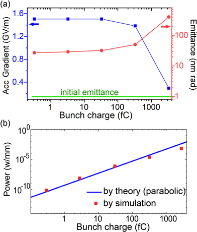
Figure 5. (a) Simulated acceleration gradient and emittance versus bunch charge. The initial beam emittance is also shown (in green). (b) Wakefield-radiation power (per unit length in transverse direction) versus bunch charge.
Download figure:
Standard image High-resolution imageTo see the achievable acceleration gradient of the present scheme, we calculate the pulse fluence (laser energy per unit area) on the prism Ws, which can be expressed as Ws ≈ |Em|2 σw/(2η). Here η is the wave impedance in the vacuum and σw is the FWHM pulse duration. The calculated acceleration gradient as functions of σw and Ws is shown in figure 6, in which the center frequency f0 of the laser pulse is chosen to be 375 THz (λ0 = 800 nm), matching that used in previous experiments [12]. The experiment-obtained breakdown threshold of quartz as a function of σw is also shown to indicate the achievable acceleration gradient. We notice that the achievable acceleration gradient can reach higher than 6 GV m−1 when the pulse duration is less than 10 fs, and it decreases to less than 1 GV m−1 as the pulse duration is more than 1 ps. Therefore, the short pulse duration requirement is an inherent advantage of ICR-DLA.

Figure 6. Acceleration gradient of the proposed model as functions of the FWHM pulse duration and the laser fluence. The dashed line represents the breakdown threshold of quartz at wavelength of 800 nm.
Download figure:
Standard image High-resolution image
3. Discussion and conclusion
Now we discuss several issues about the application of the proposed particle accelerator in practices. The first one is the synchronization between the electron bunch and the laser pulses. As indicated above, the arrival time of the laser pulse and that of the electron bunch should match at the entrances of each acceleration sections, which require a set of time and optical path controlling systems as that in previous DLAs. In practice, the source of the laser pulse can also be used to drive the photocathode of an electron gun, enabling the generated electron bunch to catch the laser pulse at the entrance of the acceleration stage. Another issue is about the initial electron energy required for the proposed accelerator scheme. As presented in [22], in order to satisfy the acceleration condition of ICR-DLA, the electron velocity should be greater than the speed of light in the dielectric medium (ve > c/n), in other words, the CR condition should be satisfied. Hence, the initial electron energy is restricted by the refractive index n of the dielectric, and should be great enough in practice.
In conclusion, we illustrate that using a few-cycle laser pulse to drive a DLA via the inverse effect of the CR is an effective way of increasing the achievable acceleration gradient. Using cascade acceleration scheme, we obtain a high energy-gain acceleration for low-energy electrons by simulation. We envisage that, with this cascaded acceleration scheme, the sub-relativity to relativity acceleration can be realized from a millimeter-scale device, promising an attractive particle accelerator on chip.
Acknowledgments
This work was supported by the Natural Science Foundation of China (Grants Nos. 12075239, U1632150, and 61471332) and by the Joint Founds of the X LAB, The Second Academy of CASIC.
Data availability statement
All data that support the findings of this study are included within the article (and any supplementary files).