

Abstract
In recent years, the applications of high-field REBa2CuOy (REBCO) coils have remarkably progressed towards NMR MRIs, accelerators, and other such devices. In a REBCO coil, the magnetic field due to the screening current is generated in the direction opposite to the field by the transport current, thus reducing the magnetic field, deteriorating the field homogeneity, and affecting the time stability of the magnetic field. Recently, the additional force and stress due to the screening current (referred to as screening-current-induced stress) has become a topic of concern. The screening current results in non-uniform current distributions in the REBCO tape. Therefore, the distribution of electromagnetic force in REBCO coils differs from that during the designing of the coil, assuming that the current flow in the tape is uniform. Thus, there is the possibility that the existence of screening current is a serious problem in the mechanical design of REBCO coils. In this study, we evaluate the electromagnetic force and stress due to the screening current by using the developed numerical simulation code for the electromagnetics and stress. We discuss the winding tension, thermal and electromagnetic stresses, and mechanical strength structure of the REBCO coil.
Export citation and abstract BibTeX RIS
1. Introduction
In recent years, the applications of high-field REBa2CuOy (REBCO) coils have remarkably progressed towards NMR MRIs, accelerators, and other such devices [1–14]. As such, studies have reported on the mechanical deteriorations or damages of the REBCO coils [8, 14]. However, the detailed mechanism of such damages has not been clarified. A REBCO coil experiences various stresses and strains during the winding process, cooling down, and charging and discharging processes. Residual thermal stress and strain are also induced in the REBCO and its substrate layers in the production process of REBCO-coated conductors. To clarify the mechanism of damages in the REBCO coils, the effects of stress and strain in these processes must be evaluated. The stress analysis in superconducting magnets have been already carried out in consideration of winding tension, cool-down and energization processes [15–18]. However, the newly mechanical issues for REBCO coils have become obvious such as the non-uniform force distribution due to screening current, no-insulation (NI) winding, non-impregnation winding and so on.
In REBCO coils, NI winding techniques are adopted for a high thermal stability and a high current density [19]. In NI coils, the current flows in the radial direction during charging and discharging. The local force occurs because of current bypass among adjacent turns away from local defects and hotspot of NI coils. The electromagnetic-force distribution in the NI coils differs from that in insulated coils. In impregnated REBCO coils, the entire winding deforms integrally owing to bonding between the turns. In contrast, each winding in non-impregnated NI REBCO coils can deform separately and move freely because of the thermal strain and electromagnetic force.
Furthermore, studies have reported on issues in such coils caused by the additional forces and stresses due to screening current [20–22]. The screening current leads to non-uniform current distributions in the REBCO tape. This biased current distribution induces distribution of electromagnetic force in the REBCO coils (hereinafter called screening current-induced stress). When designing the REBCO coil, the current is assumed to uniformly flow in the tape. Thus, there is the possibility that the occurrence of screening current is a serious problem in the mechanical design of REBCO coils.
In this study, we focus on the mechanical issues of REBCO coils such as non-impregnation winding, NI winding, the effect of co-winding and screening current-induced stress. Therefore, the thermal and electromagnetic stresses were numerically evaluated in the four cases: (a) an impregnated coil; (b) non-impregnated coil wound by a polyamide insulated tape; (c) an NI coil; and (d) a stainless-steel (SS)-tape co-wound coil, in consideration of mechanical stress during the winding process, thermal stress during the cool-down process, and electromagnetic stress including the screening current-induced stress.
2. Various stresses in the REBCO coil
2.1. Winding process
2.1.1. Bending strain.
Bending tolerance is one of the most important mechanical properties of REBCO tape for application to superconducting magnets. As such, many groups have evaluated the bending properties and uniaxial strain dependence of a REBCO tape [23–26]. As shown in figure 1, the bending strain,  , of the
  th-component layer in a REBCO tape is expressed as
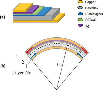
Figure 1. (a) Typical structure of REBCO tape and (b) bending of REBCO tape.
Download figure:
Standard image High-resolution imagewhere  and
and  are the radii of the ith component layer and neutral axis, respectively. Therefore,
  is the distance between the
  th-component layer and neutral axis. The REBCO layer off the neutral axis is subjected to either compressive or tensile strain. To estimate the bending strain, the position of the neutral axis must be determined; the neutral axis is not located at the centre of the REBCO tape because of the tape's asymmetric layered structure. When all the components of the composite conductor deform only elastically, the neutral axis position does not move and is determined based on the stress balance over the cross-section. However, plastic deformation of a component results in a shift of the neutral axis to maintain stress balance. The neutral axis of the composite material of n layers with different elastic properties and thicknesses is generally expressed as
where  ,
,  ,
,  , and
, and  are the Young's modulus, thickness, inner radius, and outer radius of the
  th layer, respectively. The bending axis, at which the resultant force, due to bending is null, is located at the weighted average of the layers' mid-points position,
  [27]. In this study, by assuming elastic deformation, the neutral axis determined by (2) shifts by −0.1 μm from the geometric center of the tape, therefore the effective bending strain in the REBCO could easily be calculated by using geometric center of the tape.
2.1.2. Winding tension.
If the winding loosens during the cooling and excitation stages, the wire moves, causing a temperature rise owing to frictional heat. In LTS magnets, a quench may occur owing to wire movements, whereas in HTS magnets, a quench rarely occurs due to wire movements. However, stresses and strains may exceed acceptable values owing to wire deformation [28]. Therefore, in this study, by applying tension in the winding that exceeds the thermal shrinkage at cooling and the electromagnetic force at excitation, we could prevent gaps between the windings when thermal shrinkage or electromagnetic force is applied, thus suppressing wire movement. To set the winding tension, we must consider factors such as the thermal stress or electromagnetic force as load as well as the mechanical stiffness of wire, looseness of wire after winding, and internal stress after winding [29]. Co-winding of the metal tape is also an effective method. When the tape is wound, as shown in figure 2, the following one-dimensional governing equation is formulated in the radial direction of stress [30]:
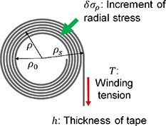
Figure 2. Schematic of the winding tape model.
Download figure:
Standard image High-resolution imagewhere  represents the incremental radial stress with increasing winding,
  is the radius of a winding turn, and
  and
and  are the azimuthal and radial Young's modulus, respectively. The REBCO tape has a laminated architecture and can therefore be approximated to an equivalent homogeneous material with transverse isotropy. Therefore,
  and
and  are calculated based on the rule of mixtures as
where  and
and  are Young's modulus and thickness of the
  th layer, which is the substrate layer, REBCO layer, and so on in REBCO tape, respectively.
  is the thickness of the REBCO tape. A rule of mixtures is a weighted mean used to Young's modulus of a composite material. Equation (4
a) represents the overall property in the direction parallel to the REBCO tape's wide face, corresponds to a axial loading.
is the thickness of the REBCO tape. A rule of mixtures is a weighted mean used to Young's modulus of a composite material. Equation (4
a) represents the overall property in the direction parallel to the REBCO tape's wide face, corresponds to a axial loading.  is volume fraction of a component layer in the REBCO tape. Equation(4
b) is the inverse rule of mixtures in the direction perpendicular to the REBCO tape's wide face, corresponds to a transverse loading. The boundary conditions are as follows:
is volume fraction of a component layer in the REBCO tape. Equation(4
b) is the inverse rule of mixtures in the direction perpendicular to the REBCO tape's wide face, corresponds to a transverse loading. The boundary conditions are as follows:
where  and
and  are the inner radius and radius of the winding turn, respectively;
  ,
,  , and
, and  are the winding tension, thickness, and Poisson's ratio of REBCO tape, respectively; and
  is the Young's modulus of the bobbin. The radial and azimuthal stresses, i.e.
  and
and  in
in  th turn due to winding tension are calculated as follows:
In this study, equation (3) is solved using the differential method, and the stress distribution is expressed using equations (6 a) and (6 b).
2.2. Cooling process
In the impregnated REBCO coils, the whole winding deforms integrally because of the bonding between the turns, while each winding in non-impregnated REBCO coils can deform separately and move freely because of the thermal strain and electromagnetic force, as shown in figure 3. Takematsu et al [31] reported on the degradation of the critical current of epoxy impregnated REBCO coils. This degradation is said to occur if the radial stresses during the cool-down and excitation stages exceeds the acceptable transverse stress for the REBCO tape. Further, dry winding and paraffin impregnation suppress degradation, as turns are separated because of the negligible bonding strength [31].
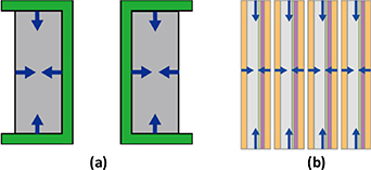
Figure 3. Thermal stress and shrinkage in coil winding and tape. (a) Deformation of the winding in the impregnated REBCO coils. (b) Deformation of each turn in non-impregnated REBCO coils.
Download figure:
Standard image High-resolution imageAs a countermeasure for degradation of the epoxy impregnated REBCO coil, Yanagisawa et al [32] suggested a polyimide-electrodeposited REBCO-coated conductor, because the tensile radial-stress concentration on the outer edge of the conductor is reduced owing to plastic deformation of the ductile polyimide. Therefore, turns in the REBCO coil are allowed to separate mechanically to avoid degradation of the REBCO tape.
2.3. Excitation process
When the coated conductors are utilized in a magnet, a high Lorentz force is exerted on them. The main component of the electromagnetic force of such wound conductors is the circumferential stress, which is applied in the longitudinal direction of the conductor. The screening-current-induced stress has become a critical issue [20]. As shown in figure 4, in a REBCO coil, the magnetic field due to the screening current is generated in the direction opposite to the transport current field, thus reducing the magnetic field, deteriorating the field homogeneity, and affecting the time stability of the magnetic field. These problems of screening current have been discussed in detail in earlier studies [20, 21]. The screening current results in non-uniform current distributions in the REBCO tape. Therefore, the distribution of electromagnetic force in REBCO coils differs from that when designing the coil by assuming that the current uniformly flows in the tape (figure 5). Thus, there is the possibility that the screening current poses a serious problem in the mechanical design of REBCO coils.

Figure 4. Mechanism of screening current in REBCO coil.
Download figure:
Standard image High-resolution image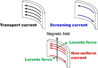
Figure 5. Additional force due to screening current coil.
Download figure:
Standard image High-resolution imageWe have been developing the 3D electromagnetic numerical-simulation code for evaluating the field error and field temporal instability due to the screening current [33, 34]. For the precise calculation of the screening-current field, we used an analysis method that allows for the winding configuration, such as the pancake and layer windings. Because the path of screening current is affected by the coil winding configuration, we developed a novel simulation code for a 3D electromagnetic field. The governing equation for the electromagnetic simulation of the screening current was formulated by assuming that the thin-film approximation is based on the Biot–Savart law, Faraday's law of induction, and Ohm's law, as expressed in (7):
where T is the normal component to the current vector potential of the tape's wide face, n is the unit normal vector to the tape's wide face, ρ is the resistivity of the superconductor, μ0 is the space magnetic permeability, B a is the external magnetic field, R is the vector toward the field point from the source point, and d is the thickness of the superconducting layer. The resistivity of superconductor, ρ, is defined using the power law and Ohm's law as
where
J
is the current density in the superconducting tape.
J
can be written in terms of the current vector potential T and the unit normal vector to the tape's wide face
n
, i.e.  .
.  and
and  are the critical current density and n-value of superconductor tape, respectively. We accounted for the critical-current dependencies on the magnitude (B) and the orientation (θ) of the magnetic field.
In this simulation, we applied the finite element method (FEM) to solve the governing equation (7). In addition, we applied the fast multipole method to the integral term in equation (7) with reduced memory usage and computational time [35–39]. Furthermore, to consider the superconducting properties, the iterative calculation using the Newton–Raphson method was adopted. However, in the case of strong nonlinearities, a large number of iterations may be required, and the iterative procedure would fail to converge. The Newton–Raphson method along with line search improves the convergence characteristics by minimizing energy functional [40]. We confirmed the validity of the numerical simulation for the screening-current-induced field [21].
3. Numerical simulation
3.1. Coil specifications
The specifications of REBCO tape and 10 T class REBCO coil in this numerical simulation are listed in tables 1 and 2, respectively. This coil consists of 22 single-pancake type stacked coils, as shown in figure 6. In this paper, the simulations were performed in the four cases: (a) an impregnated coil; (b) non-impregnated coil wound by a polyamide insulated tape; (c) an NI coil; and (d) a SS-tape co-wound coil. The numbers of turns are same in all cases. Therefore, the outer radius is different. The operating current is adjusted based on current of the non-impregnated coil wound by insulated tape to make the magnetic field at centre of coil equal. Our numerical simulation considers the dependency of critical current density (Jc) on the magnitude (B) and orientation (θ) of magnetic field, which fit with the published data [41]. The fitting functions can be referred to from [21]. In this simulation, the n-value is constant at 35.
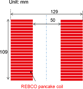
Figure 6. Cross-sectional view of the numerical model coil.
Download figure:
Standard image High-resolution imageTable 1. Specifications of REBCO tape.
| REBCO tape | |
|---|---|
| Width (mm) | 4 |
| Thickness of Hastelloy (μm) | 50 |
| Thickness of Buffer (μm) | 0.2 |
| Thickness of Silver (μm) | 2 |
| Thickness of Copper (μm) | 20 |
| Thickness of REBCO (μm) | 1 |
Table 2. Specifications of numerical-model coil of four cases: (a) an impregnated coil; (b) non-impregnated coil wound by a polyamide insulated tape; (c) an NI coil; and (d) a SS-tape co-wound coil.
| a | b | c | d | |
|---|---|---|---|---|
| Inner diameter (mm) | 50 | |||
| Outer diameter (mm) | 99.5 | 129 | 94.7 | 129 |
| Impregnation filling space (μm) | 10 | — | — | — |
| Insulator (μm) | — | 35 | — | — |
| Co-winding SS tape (μm) | — | — | — | 70 |
| Height (mm) | 109 | |||
| Turns/Single pancake | 240 | |||
| Number of single pancakes | 22 | |||
| Transport current (A) | 230 | 245 | 228 | 245 |
| Overall current density (A mm−2) | 450 | 303 | 494 | 303 |
| Magnetic field at center (T) | 11.5 | 11.5 | 11.5 | 11.5 |
3.2. Mechanical analysis
3.2.1. FEM.
We evaluated the thermal and electromagnetic stress by considering the (a) mechanical stress due to the winding tension and the bending strain during winding process, (b) thermal stress during cooling down, and (c) electromagnetic stress including screening current-induced stress. The stress was analyzed using two-dimensional axisymmetric FEM, considering the winding configuration, as shown in figure 7. The bobbin, upper and lower frames, and spacer between pancake coils are made of glass fibre reinforced plastic. The mechanical properties of the materials used in these simulations are listed in table 3 [42]. In this simulation, the Young moduli of metal and metal alloy are used at 10 K. The mean linear thermal expansion is coefficient between room temperature (300 K) and operating temperature (10 K). In this study, the transient behaviours during cooling process and the non-linear elastoplastic property were not considered.
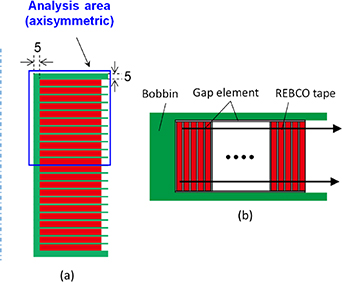
Figure 7. (a) Cross-sectional view of mechanical simulation model. (b) Detailed view of the single-pancake model. The line in (b) represents the evaluation lines of stress at 0.5 mm from upper or lower side of tape in the uppermost pancake.
Download figure:
Standard image High-resolution imageTable 3. Mechanical properties of materials in this simulation.
| Material | Young's modulus (GPa) | Poisson's Ratio | Mean linear thermal expansion (10−6 K−1) |
|---|---|---|---|
| GFRP | 35.4 | 0.21 | 10.0 |
| Stainless steel | 200 (300 K) 210 (10 K) | 0.3 | 17.3 |
| Hastelloy | 215 (300 K) 221 (10 K) | 0.32 | 12.8 |
| Copper | 127 (300 K) 138 (10 K) | 0.35 | 16.8 |
| Polyamide | 4.9 | 0.45 | 40.0 |
Generally, in a numerical simulation, the coil winding is considered as a single elastic body by the rule of mixture. Table 4 listed the equivalent Young's modulus calculated the rule of mixture for four cases. As show in table 4, the equivalent Young's modulus is lower with entering soft material in between turns. Especially, the radial equivalent Young's modulus dramatically decreases. The numerical simulations on REBCO coil as an anisotropy single elastic body were reported in [43]. However, the winding turns separate or contact in a non-impregnated coil and NI coil. In this study, the contact and separation of turns in a pancake is considered.
Table 4. Equivalent Young's modulus (GPa) in four cases: (a) an impregnated coil; (b) non-impregnated coil wound by a polyamide insulated tape; (c) an NI coil; and (d) a SS-tape co-wound coil.
| a | b | c | d | |
|---|---|---|---|---|
| Longitudinal (Circumferential) | 162.7 | 108.3 | 177.9 | 190.8 |
| Transverse (Radial) | 42.9 | 11.68 | 168.4 | 183.0 |
3.2.2. Contact model between turns.
The behaviours of deformation contact and separation of turns in a pancake is simulated. One numerical contact algorithm is the penalty method, which is well-known in FEM. However, a simple algorithm using a gap element as shown in figures 8 and 9 was adopted in this study. Contact pairs are defined between adjacent turns in a pancake. The contact problems are generally non-linear owing to changing boundary conditions. However, the contact states before and after the load application can be assumed, and if limited to a specific contact state, the state can be calculated using a linear FEM by introducing a contact element (gap element). Even if there is a contact state, at which the behavior is completely integrated before and after the load application and the analysis can be performed by approximately replacing the contact conditions with force or displacement, conventional stress analysis may be performed. A thin contact element (gap element) was inserted between corresponding nodes and elements. The thickness of the contact element was set to about 0.01–0.001 times the thickness of the nearest element so as not to affect the overall structure. In the case of an initial gap, the value of that gap is taken as the thickness.
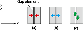
Figure 8. Gap element for contact problem. (a) Integral contact, (b) opening contact, (c) sliding contact.
Download figure:
Standard image High-resolution image
Figure 9. Gap element for contact problem. (a) Integral contact, (b) opening contact, (c) sliding contact.
Download figure:
Standard image High-resolution imageThe contact modelling is illustrated in figure 8. The  - and
- and  -axes show the anistropy that are perpendicular and parallel to the contact surface, respectively. The Young's modulus and Poisson's ratio are represented as
  and
and  , which in this case are represented as
  ,
,  ,
,  , and
, and  for the contact element, and the shear modulus is represented as
  . In the following,
  can be ignored compared to that in the structural part, such as
  in the numerical calculation. The same applies to
  and
and  .
.
- (a)Bonding contact: We assumed that the contact surfaces behave as one:

- (b)Separation: We assumed that the contacted part opens after deformation and achieves the free-boundary condition:
- (c)Sliding contact with friction coefficient: The contact portion does not open after deformation and slides freely in the direction of the contact surface:


Although the sliding contact with friction coefficient  could be considered, the friction force between adjacent turns was ignored in this study.
Figure 9 shows an algorithm of calculation of contact between turns in winding. First, the stress, as assumed in (a), was calculated; if it is a compressive stress, no separation occurs, so that the assumed contact state was appropriate. If tensile stress occurs, mechanical properties are changed to those in (b) and the stress is reanalysed. Next, when the element assumes (b) and the calculated stress is tensile, the assumed contact state is appropriate. If it is a compressive stress, as the separation between adjacent turns changes the contact state, the stress in (a) or (c) is recalculated. If a compressive stress is applied to the element assumed in (c), the separation between adjacent turns does not occur, and thus the assumed contact conditions are appropriate. If the stress is tensile, as it represents the separation between adjacent turns, we assume (b) and recalculate the stress. By repeating the above-mentioned procedure, we obtain a result indicating the correct contact state. The thermal stress and Lorentz force are gradually added at the final value by several steps in order to prevent divergence.
4. Numerical results and discussion
4.1. Screening-current distribution in the winding
Figure 10 shows the numerical results of the screening-current-induced field at a temperature of 10 K. The transport current was increased from 0 A to 245 A for 1 h, after which the current reached the constant state, and then decreased from 245 A to 0 A for another 1 h. The screening-current field at the centre position was calculated as 0.58 T at the operating current of 245 A. Figure 11 shows the distribution of current density and electromagnetic force in the winding with screening current. Figure 12 shows the distribution of electromagnetic force in the winding without screening current. As seen in figure 11(a), the current flows at both edges of the tape in the pancake coil near the medium plane. This is because the screening currents are very small as a result of the small radial component of magnetic field, resulting in a transport current that is dominant for the current distribution. Moreover, the current flows in the upper direction of the tape near the end of the pancake coil because of the high screening current. In addition, the area of the current flow is large because of low Jc near the end of the REBCO coil.

Figure 10. Numerical result of screening current-induced field.
Download figure:
Standard image High-resolution image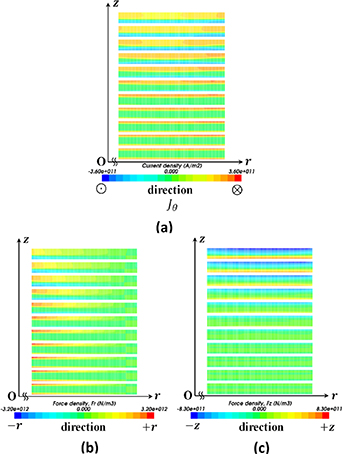
Figure 11. Distribution of (a) current, (b) radial component of electromagnetic force, and (c) axial component of electromagnetic force in the winding with screening current.
Download figure:
Standard image High-resolution image
Figure 12. Distribution of (a) radial component and (b) axial component of electromagnetic force in the winding without screening current.
Download figure:
Standard image High-resolution imageAs seen in figures 11(b) and (c), the Lorentz force distribution in the case of the screening current is completely different from that in the case of no screening current as shown in figure 12. A pair of radial electromagnetic forces of opposite directions was generated in the winding tape. The radial shear thus developed will result in a radial deformation in the direction of the width of the tape, and high local circumferential stresses will be generated at the upper part of the tape.
4.2. Deformation
4.2.1. Impregnated coil.
Next, we performed simulation on the deformation of the epoxy impregnated REBCO coil. The impregnation filling space is 10 μm. A model coil for the simulation is wound with a copper-plated REBCO tape with a winding load of 1 kg, and impregnated epoxy resin. We assumed that between turns is adhered, and the winding is adhered to the bobbin and frame. In this case, the compositions of the coil are glued, resulting in deforming coil integrally. Figure 13 shows the deformation of REBCO coil after the cooling down, and excitation. The coil shrunk during the cool down from 300 K to an operating temperature of 10 K. As shown in figure 13, the coil hardly deforms after the excitation because the epoxy impregnation reduces the deformation. Figures 14(a) and (b) shows the circumferential and radial stresses of REBCO layer in the winding on the corresponding line in figure 7(b). The radial stress is negative (i.e. compressive) after winding process and changes from compression to tension after cooling down. If the radial stress exceeds the acceptable transverse stress for the REBCO tape, i.e. a typical value of ∼10 MPa, degradation occurs. This is because the thermal contraction of impregnation is larger than that of the components of REBCO tape in shown in table 3. And the bonding strength of the impregnation is stronger than the delamination strength of REBCO tape. From the numerical results, it is confirmed that the degradation of the critical current of impregnated REBCO coils occurs because the radial stresses during the cooling process exceeds the acceptable transverse stress for the REBCO tape. The REBCO coil is carefully impregnated by considering stress or not impregnated in the dry wound [31, 32]. After an excitation, the circumferential stress increases because the winding expands outward due to Lorentz force.

Figure 13. Cross-sectional distribution of circumferential strain in winding of the epoxy-impregnated REBCO coil. (a) After cooling down, (b) after excitation. Deformation displays at 30 times scale.
Download figure:
Standard image High-resolution image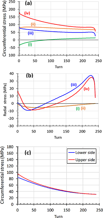
Figure 14. (a) Circumferential stress and (b) radial stress of upper side of winding in uppermost single pancake coil of the epoxy-impregnated REBCO coil. Stress (i) due to winding tension, (ii) after winding including bending strain, (iii) after cooling down, and (iv) after excitation. (c) Circumferential stress due to electromagnetic force including screening-current effect of lower and upper sides of winding in uppermost single pancake coil.
Download figure:
Standard image High-resolution imageFigure 14(c) shows the circumferential stress due to electromagnetic force including screening-current effect of lower and upper sides of winding in uppermost single pancake coil. The stress is not affected with the electromagnetic force due to a screening current. This is assumed to be the reason that deforming the winding integrally defuse nonuniform effect of screening current.
4.2.2. Non-impregnated coil wound by insulated tape.
The next case is non-impregnated coil wound by polyamide insulated tape. The thickness of insulator is 35 μm. A model coil for the simulation is wound with an insulated coated copper-plated REBCO tape with a winding load of 1 kg, and winding is not impregnated. Each winding in non-impregnated coils can deform separately and move freely. The contact between turns is modelled as mentioned in section 3.2.2. Figure 15 shows the deformation of coil after cooling and excitation. As seen in figure 15, after cooling down, the coil is not only shrinking but also distorted because of low rigidity due to non-impregnation. The outer diameter side deforms in the axial direction. Some winding is away from the adjacent turn after excitation. This reason is that screening current leads to generate the opposite direction of electromagnetic force in the tape as shown in figure 11. The circumferential and radial stresses of REBCO layer at 0.5 mm from upper side of tape in uppermost single pancake is shown in figures 16(a) and (b). The winding turns separate or lightly contact due to the thermal contraction because the stress and deformation are absorbed in the polyimide tape, therefore the radial stress almost unchanged after winding process.
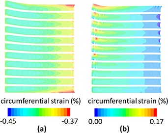
Figure 15. Cross-sectional distribution of circumferential strain in winding of the no impregnation coil wound by polyamide insulated REBCO tape. (a) After cooling down, (b) after excitation. Deformation displays at 30 times.
Download figure:
Standard image High-resolution image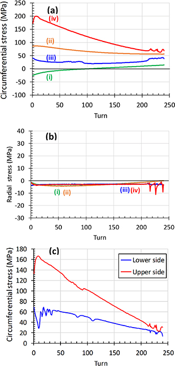
Figure 16. (a) Circumferential stress and (b) radial stress of upper side of winding in uppermost single pancake coil of the no impregnation coil wound by polyamide insulated REBCO tape. (i) Stress due to winding tension, (ii) after winding including bending strain, (iii) after cooling down, (iv) after excitation. (c) Circumferential stress due to electromagnetic force including screening-current effect of lower and upper sides of winding in uppermost single pancake coil.
Download figure:
Standard image High-resolution imageFigure 16(c) shows the circumferential stress due to electromagnetic force including screening-current effect of lower and upper sides of winding in uppermost single pancake coil. Effect of the electromagnetic force due to a screening current are remarkably appeared. The insulation coating REBCO tape shrinks during a cooling process and easily deforms against the force received by the REBCO tape during an excitation process. Therefore, the REBCO tapes in winding move and deform according to the nonuniform electromagnetic force distribution due to a screening current as shown in figure 11. Then, the stress distributions are different in the lower and upper sides of winding as shown in figure 16(c).
4.2.3. NI coil.
The NI winding technique provides a high thermal stability to the REBCO pancake coils [19]. A radial bypass current prevents the NI pancake coils from burning-out after a local normal zone appears or the coils quench. Here, the model coil is wound with a copper-plated REBCO tape with a winding load of 1 kg, and winding is not impregnated. Because the NI coil is not impregnated, each winding can deform separately and move freely. Figure 17 shows the coil deformation. As shown in figure 17, the deformation of this NI coil is reduced more than that of the non-impregnated coil wound with an insulated tape. While the NI coil is wound with a bare tape, in the non-impregnated coil wound by insulated tape, the polyamide on the tape shrinks in the cooling process, resulting in gaps between the coil turns owing to insufficient winding tension. Figures 18(a) and (b) shows the circumferential and radial stresses of the REBCO layer. The radial stress is negative (i.e. compressive) after winding process and increases to almost zero after cooling process. This is because the additional stress due to thermal contraction.

Figure 17. Cross-sectional distribution of circumferential strain in winding of the NI REBCO coil. (a) After cooling down, (b) after excitation. Deformation displays at 30 times.
Download figure:
Standard image High-resolution image
Figure 18. (a) Circumferential stress and (b) radial stress of upper side of winding in uppermost single pancake coil of NI REBCO coil. (i) Stress due to winding tension, (ii) after winding including bending strain, (iii) after cooling down, (iv) after excitation. (c) Circumferential stress due to electromagnetic force including screening-current effect of lower and upper sides of winding in uppermost single pancake coil.
Download figure:
Standard image High-resolution imageFigure 18(c) shows the circumferential stress due to electromagnetic force including screening-current effect of lower and upper sides of winding in uppermost single pancake coil. Effect of the electromagnetic force due to a screening current are slightly appeared.
In an NI winding, the elimination of low modulus, high thermal contraction materials, such as polyamide tape or impregnation, significantly increases the mechanical stiffness of the winding. Forces are directly transmitted between conductor turns resulting in near integral coil deformation. Therefore, NI winding technique was also to significantly increase the mechanical stiffness of the winding. This is significant for magnets designed for use in high electromagnetic stress environment.
4.2.4. SS tape co-wound NI coil (metal insulation (MI) coil).
Although the NI REBCO pancake coils show high thermal stability, the charging delay is an issue. Hence, to improve the charging delay, we co-wound an SS tape between the turns to increase the turn-to-turn contact resistivity [44–46]; this is termed as 'metal-as-insulation' or 'metal-insulation (MI).' A thickness of SS tape is 70 mm. Here, the model coil is co-wound with a copper-plated REBCO tape and SS tape with a winding load of 1 kg, and winding is not impregnated. The results of SS-tape co-winding with NI are shown in figure 19. The addition of stainless steel tends to decrease the overall current density as shown in table 2. However, the overall current densities of SS-tape co-winding coil is the same as that of non-impregnated coil wound by insulated tape. Comparing between figures 15 and 19, the strength of stainless steel has a larger effect on increasing effective circumferential strength than the decreasing the overall current density.
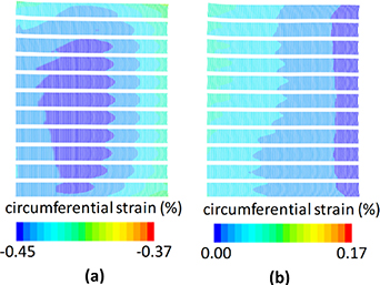
Figure 19. Cross-sectional distribution of circumferential strain in winding of the SS tape co-wound, NI REBCO coil. (a) After cooling down, (b) after excitation. Deformation displays at 30 times.
Download figure:
Standard image High-resolution imageThe stress distributions of REBCO layer are shown in figure 20. As shown in figure 20(a), the circumferential stress dramatically reduced after cooling process compared with figure 18(a). In this case, the thermal contraction of co-wound SS tape canceled the stress of winding tension. After an excitation, an additional circumferential stress is smaller than that of NI coil. And as shown in figure 20(c), effect of the electromagnetic force due to a screening current is slightly appeared as the case of NI coil.

Figure 20. (a) Circumferential stress and (b) radial stress of upper side of winding in uppermost single pancake coil of SS tape co-wound, REBCO NI coil. Stress (i) due to winding tension, (ii) after winding including bending strain, (iii) after cooling down, and (iv) after excitation. (c) Circumferential stress due to electromagnetic force including screening-current effect of lower and upper sides of winding in uppermost single pancake coil.
Download figure:
Standard image High-resolution image
5. Conclusion
In this study, we focus on the mechanical issues of REBCO coils such as non-impregnation winding, NI winding, the effect of co-winding and screening current-induced stress. Therefore, the thermal and electromagnetic stresses were numerically evaluated in the four cases: (a) an impregnated coil; (b) non-impregnated coil wound by a polyamide insulated tape; (c) an NI coil; and (d) a SS-tape co-wound coil, in consideration of mechanical stress during the winding process, thermal stress during the cool-down process, and electromagnetic stress including the screening current-induced stress.
In an impregnated coil, it is confirmed that the degradation of the critical current occurs because the radial stresses during the cooling process exceeds the acceptable transverse stress for the REBCO tape.
In a non-impregnated coil wound by insulated tape, the radial stress during cooling process decreases to below the acceptable transverse stress for the REBCO tape, however the effect of the electromagnetic force due to a screening current are remarkably appeared. The insulation coating REBCO tape shrinks during a cooling process and easily deforms against the force received by the REBCO tape during an excitation process. Removing the soft materials between winding turns is effective. In addition, it is considered that the mechanical properties are improved by decreasing the thickness of copper layer in high-filed magnets.
In an NI winding, the elimination of low modulus, high thermal contraction materials, such as polyamide tape or impregnation, significantly increases the mechanical stiffness of the winding. Forces are directly transmitted between conductor turns resulting in near integral coil deformation. Therefore, NI winding technique was also to significantly increase the mechanical stiffness of the winding. This is significant for magnets designed for use in high electromagnetic stress environment. And co-winding SS tape are also effective.
In the future, we plan to investigate the reinforcement structure of high-field REBCO coils in consideration of the transient behaviours during cooling process and the non-linear elastoplastic property were not considered.
Acknowledgments
The part of this work was supported by Grant-in-Aid for Scientific Research (C) Grant No. 16K06222 of the Ministry of Education, Science, Sports and Culture, and Research Grant (Basic Research) of TEPCO Memorial Foundation, JST-Mirai Program Grant No. JPMJMI17A2, Japan.