

Abstract
This paper focuses on the modeling and development of engineered ionic polymer-metal composite (eIPMC) sensors for applications such as postural and tactile measurement in mechatronics/robotics-assisted finger rehabilitation therapy. Specifically, to tailor the sensitivity of the device, eIPMCs, fabricated using a polymer-surface abrading technique, are utilized as the sensing element. An enhanced chemoelectromechanical model is developed that captures the effect of the abrading process on the multiphysics sensing behavior under different loading conditions. The fabricated sensors are characterized using scanning electron microscopy imaging and cyclic voltammetry and chronoamperometry. Results show significant improvement in the electrochemical properties, including charge storage, double layer capacitance, and surface conductance, compared to the control samples. Finally, prototype postural-tactile finger sensors composed of different eIPMC variants are created and their performance validated under postural and tactile experiments. The tailored eIPMC sensors show increased open-circuit voltage response compared to control IPMCs, with 7.7- and 4.7-times larger peak-to-peak bending response under postural changes, as well as a 3.2-times more sensitive response under compression during tactile loading, demonstrating the feasibility of eIPMC sensors.
Export citation and abstract BibTeX RIS
1. Introduction
Finger rehabilitation therapy has recently gained attention due to the high rate of incidence of stroke, finger injuries, and aging that can cause loss of motor function and ultimately affect a patient's quality of life [1, 2]. Mechatronics- and robotics-assisted finger rehabilitation devices are being adopted by clinicians to address the challenge of a limited number of therapists who can deliver rehabilitation exercises [3, 4]. In the past few years, passive and active rehabilitation therapies with wearable devices have been successfully used to improve muscle activity [5]. Sensor-based devices are a critical component of finger active rehabilitation systems, and they are used for sensing and measuring different movements in a human fingers [6]. In general, measuring hand and finger movements and muscle strength requires flexible, multi-functional sensors. To this end, recent efforts have focused on, for example, pneumatically-actuated devices [7] and highly stretchable strain sensors with engraved microchannels filled with conductive liquids [8] for finger rehabilitation. The demand for flexible sensing technology in smart wearable devices continues to increase and motivates exploration of flexible sensors such as resistive sensors [9, 10], capacitive sensors [11, 12], piezoelectric sensors [13, 14], optical fibers [15, 16], and electroactive polymers such as ionic polymer-metal composites (IPMCs) [17, 18]. Table 1 summarizes the advantages and disadvantages of available sensor technologies.
Table 1. Advantages and disadvantages of sensor technologies.
| Smart sensor | Advantages | Disadvantages |
|---|---|---|
| Resistive [9, 10] | Simple and low-cost fabrication, durable, wide dynamic range, low noise, good sensitivity | Nonlinear response, hysteresis, high actuation pressure, breakdown under heavy usage |
| Capacitive [11, 12] | Mechanically simple and robust, wide temperature and pressure operating range, low hysteresis and good repeatability, rapid response | Nonlinear response, sensitive to vibration |
| Piezoelectric [13, 14] | Highly sensitive, high temperatures tolerance, insensitive to electromagnetic interference, self-powered, high resolution, fast response, low cost | Good for high-frequency applications, relatively stiff, not ideal for aqueous environments |
| Optical fiber [15, 16] | Insensitive to electromagnetic interference, good in corrosive environments, highly sensitive, lightweight, wide dynamic range | Expensive, complex, fragile, susceptible to noise, crosstalk, etc, requires postprocessing |
| IPMC [17, 18] | Lightweight, resilience, self-sensing capacity, biocompatible, chemical tolerance, flexible, insensitive to magnetic fields | Low electrical response, expensive |
IPMCs are electroactive polymers that can behave as actuators and/or sensors [19, 20]. Some advantages of IPMCs include low-voltage actuation and soft and flexible structure. However, some of the challenges include low output force when used as an actuator and low electrical response when used as a sensor [21]. Additionally, it is well known that IPMCs have nonlinear behaviors when (1) driven by an electric signal for actuation (e.g. back relaxation [22]) and (2) sensing mechanical forcing parameters such as strain [23]. Work has been done on the modeling of IPMCs as self-powered sensors in [17, 24], as well as low-powered actuators (albeit with low force capabilities) [25, 26]. While responsive under bending deformations [27], traditional IPMCs exhibit limited electric response under compression, hence they are typically not considered for measuring direct force or pressure loading. However, recent advances have shown that the electric response characteristics under compression can be significantly enhanced via 'engineered' electrode-polymer features [28, 29]. In this work, 'engineered IPMCs' (eIPMCs) are created through a surface-abrading technique for applications such as postural and tactile measurement (see figure 1). The fabrication method has been found to increase open-circuit voltage sensitivity almost fivefold over unaltered polymer approaches [29]. The eIPMCs are modeled and characterized to study their multi-modal sensing capabilities, and when applied as a sensing element in a finger sensor, the postural finger information is determined with bending eIPMC strips on the proximal and distal phalanges, while tactile information is obtained with compression measurements of the fingertip. As illustrated in figure 1, compliant joint components are designed for easy attachment onto human fingers of different sizes, where bending eIPMCs are magnetically attached and the compression eIPMC is pressed within locking fingertip-collar assembly. A prototype finger sensor is fabricated to demonstrate the efficacy of the design using tailored eIPMCs. Such a device can be exploited for hand rehabilitation systems.
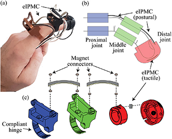
Figure 1. Concept of eIPMC postural-tactile finger sensor: (a) photograph of prototype finger sensor; (b) schematic illustrating how bending and compression of the sensors are exploited in the whole finger sensor device; and (c) solid model exploded assembly of the sensor apparatus.
Download figure:
Standard image High-resolution imageThe novelty and contributions of this work include: (1) enhanced modeling of eIPMCs to predict how these sensors can be used in multiple modalities; (2) detailed characterization of sensors that show superior electrochemical properties and high sensitivity when used under both compression and bending loading; and (3) proof-of-concept application of fabricated eIPMC sensors in a wearable postural-tactile sensing device. The new models for bending and compression sensing give insight on the effect of engineered interfaces. Sensor characterization results and the prototype postural-tactile device demonstrate feasibility of eIPMCs.
The remainder of this paper is arranged as follows. Section 2 proposes novel chemoelectromechanical models describing transduction in eIPMC sensors under compression and bending load scenarios. Section 3 discusses the fabrication of eIPMC samples using the polymer abrading technique and design and fabrication of eIPMC based postural-tactile finger sensor concept. Section 4 details the concept of the novel sensing element, including microstructure characterization, and electrochemical property testing. Section 5 outlines the experiments conducted to demonstrate the functionality of this prototype device, followed with a discussion of these experimental findings in section 6. Concluding remarks are provided in section 7.
2. eIPMC sensing model
A model for compression sensing in eIPMCs was presented by the authors in [28] based on an empirical curve-fitting function describing the dilatation through the thickness of the sensor. The solution of the resulting boundary value problem was therein pursued with the method of matched asymptotic expansions. In this paper, a new modeling approach is provided to (i) bypass technical complexities of the matched asymptotic expansion process in the solution, and (ii) describe mechanical inhomogeneities in a more intuitive way. Importantly, the new model is here extended to bending sensing in eIPMCs, which has not been presented before.
A cross-sectional view of a traditional IPMC and of an eIPMC with idealized interface model can be seen in figures 2(a) and (b), respectively, along with the relevant nomenclature. Although the engineered interface topography can be idealized as in figure 2(c), here a detailed description is not pursued; rather, a homogenized 'composite layer' region is considered, with thickness d for the interface (see [30]), that captures the mechanical properties of the bottom interface. Using the idealized interface model, the polymer and metal volume fractions in composite layer are estimated as  and
and  , respectively. Note however that, for the purpose of this model, the detailed topography of the interface is not important, as the qualitative predictions of the model are independent of it.
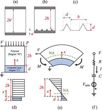
Figure 2. Schematic of: (a) plated control sample, (b) plated eIPMC with idealized periodic interface, (c) magnified view of idealized interface. (d) Top: bending sensing in eIPMC; bottom: simplified dilatation profile. (e) Top: compression sensing in eIPMC; bottom: simplified dilatation profile. (f) Equivalent circuit model for eIPMC sensor in compression or bending mode.
Download figure:
Standard image High-resolution imageFor the compression problem, a representative eIPMC cross section is schematically depicted in figure 2(d), along with the relevant nomenclature. Chemoelectromechanical transduction in the eIPMC is studied via a one-dimensional through-the-thickness problem. It is assumed that the eIPMC comprises a bulk polymer region of thickness 2h and a 'composite layer' region of thickness d, see also [30], that captures the mechanical properties of the interface between the engineered side of the polymer and the electrode. The grounded electrode is located at  and the movable conventional (nominally flat) electrode at
  . Differently from [30], the electrochemical properties of the composite layer region are assumed to coincide with those of the bulk polymer. Thus, as in [28], the charge diffusion phenomena is not considered. The mechanical stiffness of the bulk polymer region (B) and the composite layer (L) are denoted with
  and
and  , respectively. In what follows, a detailed description of the electrode surface roughness is foregone [31], assuming that the electrodes are perfectly flat, rigid, and conductive. On the other hand, the topography properties of the engineered electrode are lumped in the mechanical behavior of the composite layer region, while neglecting their effect on the electrochemical behavior.
To describe the fundamental aspects of the eIPMC mechanical behavior, the eIPMC is considered as two one-dimensional domains under plane strain, subject to mechanical, quasi-static loading conditions. A possibly time-varying uniform pressure p(t) is applied normal to the movable electrode initially at  , producing volume changes (dilatation) in the material, and consequently redistribution of charge concentration. Using the linearized governing equations from previous work [28], the Poisson–Nernst–Planck (PNP) system describing the coupled chemoelectromechanical behavior in both B and L regions is nondimensionalized as follows. Lengths are scaled with the polymer semithickness h; voltages with the thermal voltage
  , concentrations by c0, that is the fixed ion concentration per unit undeformed volume of the Nafion membrane. Time is scaled with t0, that, is the diffusion timescale in the charge boundary layer [28]. For clarity, nondimensional variables are indicated with a superimposed tilde. Upon Laplace transforming the governing equation (and using the same symbol to denote the function of time and the corresponding transformed quantity), the PNP model becomes


where  is the electric potential,
  is the net positive counterion concentration, Δ is the mechanically-induced dilatation in the solid (trace of the strain tensor), s is the (nondimensional) Laplace variable, and a prime indicates derivative with respect to the through-the-thickness coordinate
  , see also [28].
The small parameter δ represents the ratio between the Debye screening length λD
and the polymer semithickness, and for typical IPMC scenarios takes on the value of 10−6, see [32]. The central hypothesis is that, in the compression problem,  is piecewise constant in the two regions and takes on the values
  and
and  in the bulk and in the composite layer, respectively. For convenience, the applied pressure is normalized with the bulk stiffness, that is
  , so that
  and
and  , with
  . Solving in the (B) and (L) regions results in


where  , the subscript i can take the values B or L for solutions in the bulk and in the layer, respectively, and arguments of the functions are omitted for brevity. Nondimensional boundary and continuity conditions are, see also [30],


where the dependence on s is omitted,  is the nondimensional ion flux and
  is the nondimensional electric displacement. In equation (5), the moving electrode at
  is at the external voltage
  (Laplace transformed and nondimensionalized with respect to the thermal voltage
  at room temperature) while the engineered electrode at
  is fixed and grounded. Equation (6) implements ion-blocking electrodes [28]. Continuity at the interface of bulk and layer is enforced for ion flux, electric displacement, and electric potential in equation (7). Importantly, the concentration continuity in equation (8) is the mechanism for compression sensing. Indeed, rewriting equation (8) gives
  , which is a jump condition (sensing condition). As in [28], the term
  can be interpreted as a positive gain describing the mechanical asymmetry between the engineered and the grounded electrode.
The system of linear equations can be solved for the integration constants  , ...,
  . The Laplace transform of the nondimensional current through the eIPMC per unit nominal surface area is calculated as
  . For small mechanical actuation frequencies [28, 30], the complicated closed from solution can be approximated as
  , with Yc
the eIPMC equivalent circuit admittance and Gc
the transfer function between the applied pressure and the sensing voltage
, with Yc
the eIPMC equivalent circuit admittance and Gc
the transfer function between the applied pressure and the sensing voltage  , see also the circuit diagram in figure 2(f). Thus, the open-circuit voltage and the short-circuit current are determined by setting
  or
or  , respectively, thus yielding


It can be seen that equations (9) and (10) recover the results of the alternate approach from previous work [28] as  (absence of composite layer).
For the case of bending loading, as depicted in figure 2(e), the eIPMC with composite layer can be modeled as a composite beam made of two materials. Through elementary considerations, the neutral axis of bending is at a location through the thickness given by  . Denoting with κ the possibly time varying curvature imposed by the bending moment, and its nondimensional version with
  , see [23], the dilation through the thickness can be expressed as
  , which shows that in the bending problem the dilatation is a linear function of the through-the-thickness coordinate. Substituting the expression for Δ in equations (3) and (4) and proceeding in the solution as above, the current characteristic can be expressed again as
  , where now the sensing mechanism is related to the linearly varying dilatation proportional to the applied curvature. Using the low frequency hypothesis, the nondimensional open circuit voltage and short circuit current sensing for the bending problem are estimated as

If  , the results reduce to those reported in [23] for the linearized case. That is, the open circuit voltage
  is twice the curvature
  , consistently with [23, 33].
By comparing the solutions for the compression and bending problems, an equivalent circuit is derived for the sensing dynamics, as shown in figure 2(f). It is concluded that the transduction depends on a mechanical deformation driven sensing voltage  , equal to
  or
or  for compression and bending, respectively. The eIPMC electrical behavior is described by the series connection of a capacitance per unit area
  and a resistance per unit area
  . Dimensional values per unit surface area can be recovered as
 ![$R = [\mathcal{RT}(2h+d)]/[\mathcal{F}^2D c_0]$](https://content.cld.iop.org/journals/0964-1726/33/1/015035/revision2/smsad142bieqn48.gif) and
and  , where
  is the universal gas constant,
  is the absolute temperature,
  is Faraday's constant, D is the ionic diffusivity in the polymer, c0 is the fixed ions concentration, and
  is the dielectric permittivity of hydrated Nafion. The resistance increases with the eIPMC thickness
  . The capacitance is independent of the bulk thickness and is only influenced by the length scale λD
of the charge double layers (DL) developing at the electrode. The capacitance C can be interpreted as the series of two flat plate capacitors whose plates are at a distance λD
.
. The capacitance is independent of the bulk thickness and is only influenced by the length scale λD
of the charge double layers (DL) developing at the electrode. The capacitance C can be interpreted as the series of two flat plate capacitors whose plates are at a distance λD
.
Based on the developments above, the main predictions of the present model are summarized as:
- 1)In compression, VOC is proportional to the applied pressure via the transduction gain γ. For an idealized IPMC sample with nominally smooth interface, see figure 2(a), γ = 0. Hence, for the same applied pressure, VOC of the eIPMC sample is larger than that of the IPMC sample.
- 2)In bending, VOC is proportional to the applied curvature and the effective thickness. The effective thickness can be written as
 , where is the thickness of as-received Nafion, and a is the abrasion thickness. Since is smaller than that of the IPMC sample and VOC
scales with , for the same applied bending moment, VOC of the eIPMC sample will be larger than that of the IPMC sample.
, where is the thickness of as-received Nafion, and a is the abrasion thickness. Since is smaller than that of the IPMC sample and VOC
scales with , for the same applied bending moment, VOC of the eIPMC sample will be larger than that of the IPMC sample. - 3)The equivalent DL capacitance of IPMC and eIPMC samples are and , respectively, where S is the actual surface area that develops over a nominal surface area Sʹ with ratio . Thus, the equivalent eIPMC DL capacitance is larger than that of the IPMC sample.
- 4)The through-the-thickness resistance is proportional to. Therefore, the resistance of the eIPMC sample is smaller than that of the IPMC sample.


To compare eIPMCs with different interface topographies produced by the polymer abrading technique, as described below, two eIPMC samples with different interfaces are considered, qualitatively denoted as 'fine' (F) and 'coarse' (C) samples. Qualitatively,  ; the fine sample has larger number of shallow grooves, and the coarse sample has smaller number of deep grooves. Hence,
  ,
,  ,
,  , and
, and  . Therefore:
- 5)Since, the ratio is larger for fine sample which has larger actual area than the coarse sample. Therefore, the fine sample has larger DL capacitance than the coarse sample.
- 6)Since, the through-the-thickness resistance is larger for the fine sample.
- 7)Using from the inverse rule of mixtures [28], the model predicts that . Thus, for the same applied pressure, the fine sample has larger VOC output.
- 8)Since, for the same applied bending moment, VOC of the coarse sample is larger than the fine sample.


It should be mentioned that both mechanical asymmetries and effective thickness are difficult to measure without destroying the eIPMC sample. Therefore, in the following sections, the electrochemical properties (including DL capacitance and through-the-thickness resistance) are used as proxies for these mechanical properties. This is because capacitance scales with the effective area. Since differences in capacitance indicate interfacial differences for the eIPMC, larger capacitance is a proxy for larger mechanical asymmetry. Thus, we anticipate that the double-layer capacitance and the compression open-circuit voltage have similar trends. Furthermore, from our model, the resistance R scales with the effective thickness. From elementary strength of materials, for a given bending moment, the nondimensional curvature scales as  . Thus, we anticipate that the through-the-thickness resistance and the open-circuit voltage in bending have similar trends. These predictions are verified experimentally in the following sections.
3. eIPMC-based postural-tactile finger sensor
3.1. eIPMC fabrication
Customized eIPMC samples leveraging the engineered electrode concept, shown in figure 3(a) and discussed above, are fabricated using the polymer abrading technique [29]. This fabrication approach produces asymmetric and anisotropic electrode-polymer features necessary for eIPMCs. The advantage of the abrading technique is it circumvents the need for specialized additive manufacturing equipment (e.g. 3D-printers, inkjet printers, see figure 3(b)) to create the required features on the surface of the polymer material. First, the as-received ionomeric polymer (Nafion) is sanded on a single surface, in a unidirectionally manner as depicted in figure 3(c), to create parallel features. Next, an electroless plating process is used to apply platinum electrodes to the surfaces of the materials. The plating process is similar to standard IPMC manufacturing [29], and is not described here for brevity. After fabrication, the plated features can be macroscopically observed in figure 3(d1)–(d3), where a control IPMC sample created with no abrasion, a coarse abrasion eIPMC (220-grit sandpaper, average particle size of 53–74 µm), and a fine abrasion eIPMC (400-grit sandpaper, average particle size of 20.6–23.6 µm) demonstrate oriented, anisotropic grooves on the treated electrode surface. Previous works demonstrate both via modeling [28] and experiments [29] that this anisotropic surface structure directly affects the sensitivity of the eIPMC under compression loading scenarios.

Figure 3. Engineered IPMCs: (a) metal plated electroactive polymer with 'engineered' anisotropic features on the grounded polymer-electrode interface; (b) 3D-printing approach for controlled anisotropic features via layering; (c) polymer abrading approach for large surface area features removed from bulk ionomer; (d) fabricated IPMCs using (d1) no abrasion (control IPMC), (d2) coarse abrasion eIPMC, and (d3) fine abrasion eIPMC.
Download figure:
Standard image High-resolution image3.2. Mechanical design of finger sensor
The mechanical design of the components of the postural-tactile finger sensor is accomplished using the 3D modeling software SolidWorks. Postural orientation of a finger equipped with the proposed wearable sensor is obtained relative to affixed joint pieces grasping onto the finger's phalanges, schematically shown in figure 1(b). This is achieved with a ring-like joint piece, shown in figure 1(c). These joint pieces are designed with compliant thin semicircle hinges which wrap around the finger, expanding the size of finger which are suitable for the design. Magnetic recesses are included on both edges of the piece's top face, which serve as the attachment points for the bending eIPMCs attaching to the joint. This piece attaches to the proximal and middle joints of the finger, where curling motion keeps the joints in place while the bridging eIPMCs experience primarily bending mechanical deformation.
While grasping compliant joints are well suited for the finger orientation measurements, a different mechanism is required for the distal joint in which compression loads are applied. Thus, the furthest joint of the finger sensor consists of two pieces, again shown in figure 1(c). A small collar piece slides onto the finger tip, where the inner diameter is sized for the appropriate digit. This collar interlocks into an outer tip piece, where a small eIPMC swatch is placed between the flat contacting surfaces. With hemisphere contact surfaces serving as the artificial finger tip, pressure applied by a finger wearing this device will compress the tip piece onto the collar, and consequently the eIPMC material within. The closest bending eIPMC strip is again magnetically connected on the top of this joint piece via a recessed magnet.
3.3. Assembly of sensor components
The entire postural-tactile sensor is assembled according to the exploded view in figure 1(c). The joint pieces are manufactured via 3D-printing with polylactic acid (PLA) plastic, where small neodymium magnets are epoxied into the recesses within the design. Bending and compression eIPMC are created using the polymer abrading technique mentioned above in section 4.1. Long thin bending samples (37 mm × 3.0 mm) and smaller compression samples (9.0 mm × 5.5 mm) are cut from bulk eIPMC sheets; a total of three eIPMC sets are chosen to investigate within the sensor apparatus: no abrasion, coarse abrasion, and fine abrasion. Three sensor variants are built with these eIPMC sets, where the electrical performance of the electroactive material sets is of interest. Specifically, tailoring the eIPMCs to be most responsive for bending and compression modalities needs to be determined, via chemoelectromechanical characterization, modeling, and experimental validation.
4. Surface characterization and electrochemical testing
This section compares the microstructural properties of the eIPMC samples fabricated with the polymer abrading technique to better understand how they behave, both generally and towards the proposed postural-tactile finger sensor. This comparison aims at establishing the relationships between processes and structure within the sensor. Surface characterization is conducted using scanning electron microscopy (SEM) to study the surface topography qualitatively. Varying microstructures are expected to significantly affect the electrochemical properties of the samples; thus, a thorough suite of electrochemical tests is performed to establish the structure-property relationships.
4.1. Surface characterization
To observe the abrading effect before and after plating, SEM images are captured for all three sample types. Because SEM imaging requires a conductive surface for the electron flux process, the bare Nafion membrane is coated with a thin layer of gold (approximately 30 nm thick) prior to imaging. This coating does not influence the microstructural topography, whose characteristic dimensions are several orders of magnitude larger than this coating. Selected experimental views are shown in figure 4, through SEM images with 350 × magnification. Before plating, the polymer abrading technique impresses aligned unidirectional grooves approximately in the shape of straight lines. No obvious surface features can be identified on the control sample. The fine grit abrading material (e.g. figure 4(a3)) leaves a cleaner surface after abrasion, while displaced debris can still be observed in the neighborhood of the grooves for the coarser-grit abraded material (figure 4(a2)). The coarse grit material is seen to leave deep and wide grooves, while the fine grit material produces a larger number of finer grooves, per unit area.
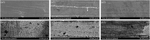
Figure 4. Scanning electron microscope (SEM) micrographs of eIPMCs with 350× magnification: (a) polymer (Nafion) membrane before plating process, with (a1) no abrasion, (a2) coarse abrasions, and (a3) fine abrasions; (b) plated Nafion membrane with (b1) no abrasions, (b2) coarse abrasions, and (b3) fine abrasions. Note the presence of mud-crack-like platinum islands on the plated surfaces.
Download figure:
Standard image High-resolution imageMuch of the surface features produced on the Nafion membranes are preserved upon electroding and seen on the metal surfaces of the eIPMCs, shown in figures 4(b2)–(b3). In the plated samples, the plating process produces a metal surface that generally follows the underlying surface features. This point is central to the process of surface engineering.
As observed in previous IPMC research [34, 35], the platinum coating does not produce a perfectly smooth cover on the membrane, and the presence of 'mud-crack'-like platinum islands on the faces of the samples can clearly be observed. Their characteristic dimensions, of microscale size, depend on the surface grooves impressed on the polymer membrane. It is hypothesized that surface grooves may act as surface stress release regions, thus ultimately affecting the characteristic size of the resulting platinum islands. Specifically, comparing the control sample with coarse- and fine-abraded samples, it is seen that the abraded samples have more and finer mud-crack-like islands per unit surface area. While these general features were observed before in the IPMC literature, they demonstrate that the polymer abrading technique is capable of affecting the characteristic sizes of the islands, which in turn affects the surface electrochemical properties, discussed in the following section. Thus, besides the effects that polymer abrasion has on mechanical properties, this process is able to include direct electrochemical property adjustment in the design of the sensors via the engineered surfaces. This novel result parallels the progress in process-structure-property relationships for isotropic surface roughening as described for example in [36].
4.2. Electrochemical testing
In order to understand the process and structure effect on the electrochemical properties of different sample types, electrochemical tests, including cyclic voltammetry (CV), chronoamperometry (CA), and surface conductance (SC) measurements, are conducted on the plated samples to determine charge storage and DL capacitance (using CV), through-the-thickness resistance (using CA), and SC using two-point resistance measurements. A total of twelve  samples are tested: four for each eIPMC abrasion type. Each sample is tested multiple times to ensure repeatability: three times in CV, six times in CA, and ten times in SC. Adhesive copper tape is firmly attached to each surface electrode, and all the electrochemical tests are performed 30 min after full submersion in deionized water. The experimental setup and test parameters are similar to previous work [28]. Results from these characterization tests are displayed in figure 5 with the no abrasion samples serving as the control (CTRL).
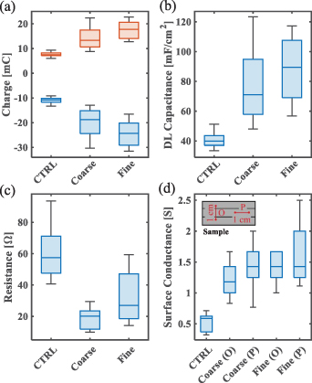
Figure 5. Electrochemical tests results from left to right, top to bottom: positive (red) and negative (blue) charge storage measured via CV; DL capacitance measured via CV, through-the-thickness resistance measured via CA, and surface conductance measured in a direction parallel (P) and orthogonal (O) to the grooves.
Download figure:
Standard image High-resolution imageBox-plots of the positive and negative charge storage, and the DL capacitance of all samples, figures 5(a)–(b), are extracted from CV tests according to [28, 37]. Experimental results show that the polymer abrading process significantly improves the peak current density, the amount of charge stored, and the DL capacitance. The latter exhibits an approximately two-fold increase between the control samples (approximately  ) and the eIPMC samples (approximately
  ). Large DL capacitance has been associated to enhanced actuation and sensing performance in IPMCs [31].
Current results via a voltage step input in CA were used to determine the through-the-thickness resistance from the peak current at the beginning of the charge/discharge process. It is seen in figure 5(c) that the through-the-thickness resistance is reduced of a factor of approximately 2–3 between the control sample and the eIPMC samples. Finally, results of the SC characterization performed via a two-point resistance measurement are shown in figure 5(d), where multimeter probes are kept at a fixed distance of  and surface conductivity is measured on the metal electrodes in directions parallel and orthogonal to the grooves to evaluate possible anisotropy. As figure 4 shows, the polymer abrading technique produces a larger number of finer scale platinum island which improves SC as compared to the control sample. As expected, conductance is slightly anisotropic, being larger in the direction parallel to the grooves.
The data scatter is likely a result of the non-uniform roughness created using the abrading technique, the nature of IPMCs which have a time-dependent behavior, and non-uniform plating over different regions of the sample surfaces. However, these observed enhanced characteristics demonstrate how the polymer abrading technique is useful for improving properties associated with better sensing IPMCs.
As can be seen in figure 5, both fine and coarse eIPMCs have larger capacitance and smaller resistance than the control sample, which is consistent with the model predictions (3) and (4), respectively. In addition, the fine sample has larger capacitance and resistance than the coarse sample, which confirms the model predictions (5) and (6).
5. Experiments
Based on the characterization and electrochemical testing results in section 4 and the modeling developed in section 2, the eIPMC-based postural-tactile finger sensor prototype is assembled with the different eIPMC samples and used to measure finger orientations and loading forces. Open-circuit voltage signals are measured from the bending eIPMCs connecting the joint pieces of the device along with the compression eIPMC sensor embedded within the distal fingertip pieces, using a Wheatstone bridge circuit and operational amplifier signal conditioning as shown in figure 6. In particular, a load cell calibrated with known pressures serves as the application surface for the loads generated by the finger outfitted with the sensor apparatus. These voltage signals are amplified with operational amplifier circuits (LM324; inverting amplifiers for the eIPMCs, differential amplifier for the load cell) and recorded using a National Instruments data acquisition system (USB-6009). The bending eIPMC responses are amplified by 9 × while the compression eIPMC is given a 190× amplification due to the relatively lower sensitivity of this modality.

Figure 6. Experimental setup for eIPMC-based postural-tactile finger sensor; eIPMC open-circuit voltages are amplified to utilize range of DAQ hardware.
Download figure:
Standard image High-resolution imageExperimental trials consist of postural and tactile sessions for the assembled finger sensor. First, the open-air orientation of the measured finger is determined from the open-circuit voltage response of the recently hydrated bending eIPMCs (both proximal and middle pieces), shown in figure 7(a). This experiment consists of the sensed finger being bent forwards and backwards between a nominal position (Np) and curled position (Cp). These positions are initially held for 1 s between transitions; four cycles are conducted at this rate. Then the rate of transition between Np and Cp orientations are made every 0.5 s, again for four cycles. The curvature of the finger is estimated from the video recording of the experiments, where still images are extracted at each cycle of the trial and a curve is fit to the manually approximated finger using a least-squares fit. Because the finger in each experiment is approximately planar with respect to the camera lens, this is assumed to be a reasonably accurate approximation of the true curvature of the finger for the purposes of this work. The sensitivity is calculated based on the change in magnitude in the eIPMC voltage between the Np and Cp orientations, depicted in the box-plot of figure 7(b). The time response for the sensor is shown for the coarse eIPMC set in figure 7(c).
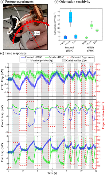
Figure 7. eIPMC postural measurement experiments: (a) Experimental setup; finger posture is cycled from nominal position (Np) and curled position (Cp) and finger curvature  is estimated from video recording. (b) Box-plot of eIPMC sensitivity to finger curvature. (c) Time responses of posture experiments.
Download figure:
Standard image High-resolution imageNext, the tactile experiments consist of the sensed finger pressing onto the load cell, as shown in figure 8(a). The outfitted finger applies a pressure for 1 s, then releases for 1 s, repeating the cycle once. The application and release times are decreased to 0.5 s for four additional cycles, after which the trial concludes with a press-and-hold application of the finger onto the load cell. The sensitivity is calculated based on the change in magnitude in the eIPMC voltage during compression and depicted in the box and whisker plot figure 8(b). The time responses for the eIPMC sensor variants are shown for these trials in figure 8(c). It should be noted that while the intent for these compression tests is to apply a step compression, because loading is applied by the outfitted finger the response has a clear build-up to the held force. However, the step response of eIPMC under compression has been previously shown by the authors [28], where no significant drift is observed in the sensor. This is similarly observed in the experiments conducted here.
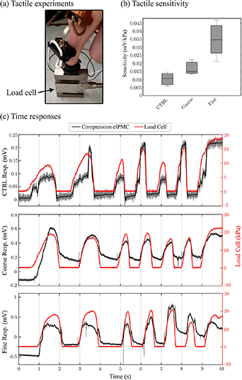
Figure 8. eIPMC tactile measurement experiments: (a) Experimental setup; compression loading is cycled onto a load cell by the sensed finger. (b) Box-plot of eIPMC sensitivity to compression loads. (c) Time responses of tactile experiments.
Download figure:
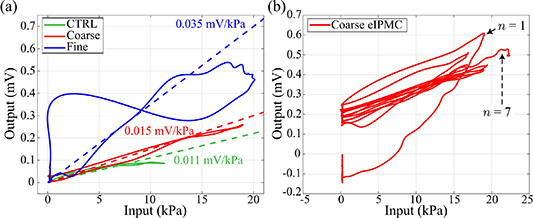
Standard image High-resolution imageDynamic behavior for the compression sensing modality is demonstrated via the input-output plots for the eIPMC variants, shown in figure 9. These experiments show a mild degree of time-varying behavior of the eIPMCs and nonlinear effects such as hysteresis, a well-know effect in IPMCs both as an actuator and sensor [38]. A comprehensive study of the dynamical behavior of eIPMCs requires a separate effort, which is beyond the scope of this article. Recognizing its significance, our group is currently engaged in both theoretical and experimental investigations into the dynamical behavior of eIPMC sensors under external compression loads with different frequencies, as part of a distinct research endeavor.
Figure 9. Input–output curves for the compression eIPMCs in the wearable finger device. (a) Single cycle of all sensor variant compared with estimated linear sensitivity. Approximately linear responses are observed (CTRL and Coarse eIPMCs), although nonlinearities can affect the falling response of the sensor (Fine eIPMC). (b) Multiple loading cycles demonstrate hysteresis and time-varying effects on sensor output. Cycle number n is indicated for the initial peak (n = 1) and final held voltage (n = 7). After initial cycling, curves largely overlap each other.
Download figure:
Standard image High-resolution image
6. Discussion
The postural experiments trial shown in figure 7(c) highlight the response of the eIPMCs in bending. The control eIPMC sensors exhibit the poorest performance, where minimal open-circuit voltage is measured in either eIPMC, while the coarse eIPMCs demonstrate the largest sensitivity. As the finger changes in posture from the nominal (straight) position to the curled position, the proximal bending eIPMC responds approximately proportionally, where some voltage build-up occurs while the curled position is held during the lower-speed cycles. Alternatively, the middle eIPMC is more susceptible to decaying back to its initial voltage level, both during the 1 s and 2 s cycle periods. This difference is likely due to the middle eIPMC being in a pre-bent (buckled) state, where the proximal eIPMC is nominally straight along with the finger. This phenomenon agrees with the literature, where buckled IPMCs have been shown to have large spikes in the open-circuit current during deformation [39]. It is also noted that the time responses show a dynamic relationship between the open-circuit voltage rather than a proportionality as predicted by the model presented herein. These deviations are a consequence of the nonlinear effects present in eIPMC sensors, which can largely be attributed to dehydration effects from in-air use over the experimental trials. While these nonlinearities do add deviation to the sensitivity measurements, such behaviors can be addressed using more controlled manufacturing and deployment methods, such as encapsulation with parylene [40] and are not the focus of this work. However, these different response shapes can reasonably be used together to provide information on the absolute orientation of the finger as well as when changes in orientation are occurring (e.g. position and velocity).
The most responsive eIPMC sensor is the coarse abrasion set, with the median sensitivity to finger curvature being 55.6 mV cm−2 and 36.6 mV cm−2 for the proximal and middle bending eIPMCs, respectively. The fine eIPMCs samples are the next most responsive, with the proximal and middle bending strips exhibiting median peak-to-peak voltage responses of 9.18 mV cm−2 and 24.9 mV cm−2. The least responsive are the control IPMCs with voltage responses of 7.18 mV cm−2 and 7.73 mV cm−2, again for the proximal and middle IPMCs respectively. As can be seen, the coarse set is approximately 7.7-times more responsive than the control for the proximal sensor, although larger variations in response are observed; this is likely due to the voltage build-up effect observed, which is stunted during the higher-speed oscillations later in the experiment trial. The middle bender is also observed as significantly more responsive for the coarse set, with a 4.7-times increase in the median response over the control sensor. The finer abraded eIPMC also demonstrates a large gain in response for the middle bender, with more than three times the response of the control set. Overall, these results indicate the coarse abrasion set is most responsive when deployed in the bending configuration for postural measurements, although deviations between specific samples are to be expected. These results are consistent with the qualitative model predictions (2) and (7).
The tactile trials experiment shown in figure 8(c) highlight the coarse eIPMC compression results, where similar behavior is observed for the fine and CTRL sensors. The compression sensor's voltage response is approximately proportional to the force applied to the load cell as predicted by the proposed eIPMC model. Additional dynamic effects, such as hysteresis and time-varying phenomena (dehydration), are observed in the sensor, shown in figure 9, which is expected and consistent with the IPMC literature [38]. First, looking at a single cycle of the compression sensors' input-output behavior in figure 9(a), the coarse and CTRL sensors demonstrate nonlinearities that resemble hysteretic loops found in electromechanical devices [41]. The fine eIPMC compression sensor is somewhat anomalous, with the return path of the cycle experiencing an additional voltage increase as the pressure nears zero. This is likely due to irregular geometric interaction of the eIPMC within the tactile mount, caused by eIPMC curvature and sensor slippage and not the sensor manufacturing process itself. Time-dependent effects are highlighted for the coarse eIPMC in figure 9(b), where similar behaviors are present for the other sensor variants. Cycling the applied finger pressure can result in largely linear input-output relationships, as the experiments conducted here demonstrate largely indistinguishable curves after about three cycles indicating any charge buildup has been dissipated during the dynamic loading. The form of these time-varying effects depend on factors such as hydration levels and initial deformation and loading, which are largely uncontrollable in the prototype device manufactured in this work. These phenomena can be mitigated using advanced techniques such as neural networks and hysteresis inversion models to effectively linearize the sensor response; such methods are outside the scope of this work.
Under compression, the most sensitive eIPMC set is the finer abrasion sensors with a median response of 0.035 mV kPa−1. This is about 3.2× more sensitive than the control with a 0.011 mV kPa−1 median sensitivity, and more than 2× the 0.015 mV kPa−1 response sensitivity of the coarser abraded sensor. These results align with the qualitative model predictions (1) and (7). Interestingly, the electrochemical and modeling results show that the DL capacitance and compression VOC have similar trends as they both are function of φm
. In addition, the resistance and bending VOC have similar trends as they both are function of  . Thus in practical design settings, eIPMC capacitance and resistance could be used as proxies for effective surface area and thickness, respectively, which are inaccessible via nondestructive measurements.
There are coupling effects observed between the bending and compression eIPMCs. During tactile operation, bending eIPMCs would experience excitation in their measured electric potential approximately 10%–20% in magnitude of that observed during postural trials. This is a reasonable behavior, since compression loading on the finger will propagate down the entire finger. The compression eIPMC is significantly decoupled from bending motion, where observed signals were indistinguishable from the noise. This allows for sensors to be directly decoupled, or incorporated into more advanced estimation algorithms such as Kalman or particle filters.
Most of the factors causing larger data scatter in eIPMC samples, compared to the control sample data in figures 7 and 8 are similar to those producing a similar scatter in electrochemical test results. One of the significant differences between electrochemical tests and the output voltage measurement process is that, during the electrochemical tests, the samples were placed in deionized water; therefore, dehydration does not affect the test results. Conversely, during voltage measurements, all the pre-hydrated samples operated in the air. Therefore, dehydration can impact the test results. Specifically, electrochemical tests were performed on undeformed samples, while voltage measurements were taken during the application of external force on samples. Applying external force can increase water leakage or dehydration rate through the porous electrode, reducing sensor efficiency. Different external loads (bending and compression) and interface micro-feature sizes (coarse and fine samples) can result in different dehydration rates. In particular, electrode porosity may be strongly related to the platinum 'island' size and distribution that are affected by the polymer abrasion process, see figure 4. These factors may be additional reasons for the varied data scatter observed in fine and coarse eIPMC samples.
In conjunction, these two trials demonstrate the individual sensing capabilities of the eIPMC-based postural tactile finger sensor concept, where electrode surface features can be engineered to tune the sensitivity of each sensor component of the apparatus. The device can be used to show orientation changes in a digit, along with any tactile loading which that digit applies. If several devices are outfit onto a patient's hand, this information can be used to enhance rehabilitative exercises, where the finger information can be fed back and improve exercises assigned to the patient, potentially in real-time. Furthermore, in remote care scenarios, this information can be recorded or broadcast to ensure more independent patients are participating in self-care exercise routines.
All experiments conducted in this work are on freshly-fabricated eIPMC sensors, as immediate performance gains over the traditional sensor variant is what is investigated here. However, eIPMCs are expected to degrade over time as the sensors wear, as the engineered features are not hypothesized to improve robustness in the material's lifespan. Further investigation into the long-term performance of the eIPMC sensors (e.g. durability and sensitivity over time) is expected to behave similarly to traditionally-manufactured IPMCs. Future research into this behavior should be considered to further understand eIPMC utility in rehabilitative mechatronic and robotic devices.
7. Conclusions
This paper focused on the modeling and development of eIPMC sensors, and the fabricated sensors were implemented in a postural and tactile wearable device for potential application in finger rehabilitation therapy. A new model for determining the bending and compression sensitivity of eIPMCs was presented. Surface characterization, both before and after plating the Nafion membrane, and electrochemical testing were performed on eIPMC samples. Charge storage, DL capacitance, through-the-thickness resistance, and SC measurements demonstrate the impact of the surface roughing process of the polymer abrasion technique in manufacturing eIPMCs. The wearable device that incorporated eIPMC was based on a modular design, consisting of compliant phalange-clamping ring joints, a two-piece interlocking fingertip component, and magnetically affixed eIPMC sensors, enhanced with anisotropic electrode-polymer surface characteristics. Postural and tactile experimental trials demonstrated the prototype device, in which bending eIPMCs show the orientation of the sensed finger, while the compression eIPMC demonstrated tactile responses proportional to the applied finger force. Specific device sensitivity can be selectively tuned, as coarser surface abrasions showed higher bending sensitivity while finer abrasions resulted in higher compression sensitivity. Sensitivities were correlated in both cases to the electrochemical properties, consistently with model predictions thus closing the process-structure-property-performance loop. The customized eIPMC sensors exhibit an enhanced open-circuit output voltage response in comparison to non-engineered IPMCs. They display peak-to-peak bending responses under postural changes that are 7.7 and 4.7 times larger, respectively, and a 3.2 times more sensitive response under compression during tactile loading. This showcases the great potential benefits of eIPMC sensors over their traditional counterpart. Notably, the fabrication process for both non-engineered and engineered IPMCs does not significantly differ in terms of equipment, time, and costs. Consequently, we believe that it is advantageous for our community to easily substitute traditional non-engineered IPMCs with the innovative eIPMCs when sensing applications are desired. This concept can be extended to multiple finger sensors and utilized in rehabilitative or self-care medical applications, providing non-invasive hand and finger information for higher-level monitoring, learning, or control.
Acknowledgments
This research was supported, in part, by the National Science Foundation under Grants 1809852, 1809455, and 1545857. Any opinions, findings, and conclusions or recommendations expressed in this material are those of the authors and do not necessarily reflect the views of the sponsor.
Data availability statement
The data that support the findings of this study are available upon reasonable request from the authors.