
Abstract
Soft robotic grippers have gained considerable attention owing to their highly compliant, adaptive, and safe characteristics in a large variety of scenes, especially involving human-machine interactions. However, the low-stiffness nature of the soft material and the multi-finger gripping mechanism make soft grasping systems suffer in applications requiring relatively high load capacity and broad grasping adaptability. Despite extensive efforts to develop soft grippers with tunable stiffness by constructing smart materials and structures, the resultant load capacity is often compromised by sacrificing working efficiency or surface adaptability. In this work, we report a paradigm to design a versatile, high-load (>2 kg), and fast-response (<1 s) pneumatic soft gripper by strengthening the contact interface via bio-inspired controllable adhesion. A mushroom-shaped micropatterned dry adhesive surface is integrated with a soft pneumatic bidirectionally bendable actuator via a vacuum-assisted equal load-sharing design. This gripper extends the adaptable object diameter from 15 mm to infinity and significantly increases the load capacity to over 2 kg without compromising the original compliance. The multifunctional grasping modes and high load capacity are successfully demonstrated by grasping objects with diverse material components, various surface shapes.
Export citation and abstract BibTeX RIS
1. Introduction
Robotic grasping and manipulation have evolved from traditional rigid joints to emerging soft actuators in the past decade owing to the low cost, easy control, and safe interaction properties of the soft constituent materials [1–4]. Advances in soft robotics and material science have facilitated the broad applications of soft grippers in dexterous grasping [5–7], postoperative rehabilitation [8–10], haptic interactions [11–13], etc. However, the intrinsic low-stiffness nature of the soft material makes soft grippers suffer in tasks requiring a high load capacity, especially for manipulating heavy objects. Besides, it is very challenging for a robot to grasp and manipulate uncertain objects of varying shapes, sizes, weights, and properties in various unstructured environments without replacing the gripper accessories.
To enhance the load capacity of soft grippers without losing the original soft properties, extensive efforts have been made to exploit smart materials and structures exhibiting tunable stiffness. External field responsive materials such as shape memory polymers (SMPs) [14–16], electrorheological and magnetorheological fluids [17], and low melting point alloys (LMPAs) [18–20] were employed and integrated with existing soft actuators, exhibiting well-controlled stiffness via external thermal, electric, and magnetic field. Nevertheless, these smart materials usually suffer from the tradeoff between a high stiffness switching ratio and a short state switching time. For example, LMPAs can be transitioned from liquid to solid by regulating their temperature, resulting in a stiffness switching ratio of several orders of magnitude. Nonetheless, the transition time ranging from dozens of seconds to several minutes especially in the cooling phase is barely satisfactory for actual applications. In comparison, smart structures such as rigid-soft coupled structures and granular/laminar jamming structures [21–25] can enhance stiffness rapidly, yet at the cost of sacrificed compliance or limited stiffness switching ratio. As a matter of fact, the load capacity of soft grippers for a relatively small object is mainly made up of the friction force generated by clamping and the supporting force generated by wrapping. The stiffening of the soft gripper after clamping increases the stiffness against the gripper deformation induced by the gravity of the grasping object, thereby enhancing both the friction force and the supporting force contribution to the load capacity.
Previous studies mainly focus on bulk stiffness modulation strategies, which must make a tradeoff between stiffness switching and working efficiency. Alternatively, this dilemma can be broken through by considering the surface design to strengthen interfacial adhesion and friction. Gecko-inspired micropatterned dry adhesive surfaces with controllable adhesion and friction have been extensively studied, exhibiting a promising application in robotic grasping and manipulation [26–37]. For example, Hawkes et al proposed a shear adhesion gripper made of a flexible yet inextensible film bonded with micro-wedged structural arrays, which can easily grasp curved and heavy objects without squeezing [27]. Song et al presented a pressure-tunable soft gripper integrated with mushroom-shaped micropillars, which is versatile for grasping various delicate objects [31]. These remarkable works strongly demonstrated the interfacial effect of the gecko-inspired micropatterned dry adhesive surface, which barely need to consider the bulk structural design. By combining fluidic elastomer actuators and gecko-inspired micro-wedged adhesives, Glick et al demonstrate a soft robotic gripper with higher grasping strength at lower input pressures [33]. The enhancement of the gripping force contributed by improved friction is significant for relatively small objects. However, it still suffers from the limitation of small friction contribution for objects with larger sizes than that of the gripper. This limitation of grasping large-sized objects also exists for most grippers, as the friction force along the surface profile gradually deviates from the gravity and the supporting force does not exist anymore without wrapping.
To address the main challenges of high load capacity and varying shape adaptability for soft grippers, in this work, we report a paradigm to design and fabricate a versatile, high-load (>2 kg), and fast-response (<1 s) pneumatic soft gripper by strengthening the contact interface via bio-inspired controllable adhesion, as schematically shown in figure 1(a). The gripper is mainly composed of a soft pneumatic bendable actuator and a mushroom-shaped micropatterned adhesive surface, sandwiched by a thin vacuum chamber. The geometrical structure is optimized by modeling the bending behavior and proposing a rolling contact strategy. The integrated soft adhesive gripper exhibits an enhanced load capacity without sacrificing the original flexibility. Moreover, the effective grasping diameter has been extended from 15 mm to infinity thanks to the shape-configurable micropatterned adhesive surface. The underlying load-sharing mechanism was revealed by finite element method (FEM) simulations, which agrees well with the experimental results. Furthermore, the multifunctional grasping modes and high load capacity were successfully demonstrated by grasping a variety of objects with different features.

Figure 1. The structural construction and working principles of the soft adhesive gripper. (a) The typical grasping and manipulation application of the proposed soft adhesive gripper composed of a soft pneumatic actuator and bio-inspired micropatterned adhesion. (b) 3D model and (c) fabricated prototype of the soft adhesive gripper. (d) Explosive view of 3D disassembling of the soft adhesive gripper. The inset shows the scanning electron microscope (SEM) image of the used mushroom-shaped dry adhesive surface. 1: Vacuum tube, 2: loading bar, 3: pressure tube, 4: PTFE tube, 5: tendon, 6: releasing bar, 7: soft actuator, 8: soft bottom layer, 9: steel sheet, 10: Sil-Poxy adhesive frame, 11: PET film, 12: adhesive layer, and 13: mushroom-shaped micropillars. (e) The grasping mode and corresponding stress distribution and contact states of the soft adhesive gripper for curved objects by providing positive pressure for the pressure chamber and negative pressure for the vacuum chamber. (f) The releasing mode and corresponding stress distribution and contact states of the soft adhesive gripper by removing the external pressure while retracting the tendons.
Download figure:
Standard image High-resolution image2. Results
2.1. Structural design and working principles
The section views of the 3D model and the prototype of the soft adhesive gripper are shown in figures 1(b) and (c), respectively. To describe the laminated design of the gripper in detail, the 3D model is disassembled into the explosive view shown in figure 1(d). The soft pneumatic bendable actuator with gradually varied trapezoidal chambers is bonded with the soft bottom layer to form a sealed pressure chamber. By controlling the positive air pressure pumped through the pressure tube, the pneumatic actuator can bend inward (towards the side of the bottom layer) to a specified level. To help the actuator bend outward (towards the side of the actuator chamber), an extra contracting mechanism composed of conduits and tendons is carefully assembled at the top of each chamber. By contracting the tendons with an embedded servo motor, all the chambers are squeezed together to make the actuator bend reversely. Therefore, the soft pneumatic actuator can bend bidirectionally by utilizing the pressurized and mechanical modulation methods.
It should be noted that the adhesive layer is not directly bonded to the soft bottom layer due to the poor adhesion performance, which will be elaborately discussed in the next section. In comparison, the adhesive layer is connected to the soft bottom layer via a sandwiched thin vacuum chamber. The vacuum chamber is constructed by isolating a flexible steel sheet and a polyethylene terephthalate (PET) film with a ∼100 μm thick Sil-Poxy adhesive sealing frame. A vacuum tube is carefully assembled and connected to the vacuum chamber to provide a uniform negative pressure across the vacuum chamber. The adhesive layer is micropatterned dry adhesive surface with vertically aligned mushroom-shaped micropillars, as shown in the inset of figure 1(d).
As shown in figure 1(e), when the gripper is inflated in the pressure chamber, it can bend conformably to a curved substrate with intimate contact. Then the vacuum chamber is vacuumized to provide an equal load sharing among the contacted micropillars (see the insets off figure 1(e)). Therefore, the gripper can grasp curved objects with different curvature radius. When the grasping task is finished, the pressure chamber is deflated to actively release from the object. However, the stored elastic energy during bending may be not enough to break the adhesion force on substrates with small curvatures, especially flat surfaces. Therefore, the retraction mechanism is also actuated to reversely bend the actuator, leading to a large angle peeling of the adhesive layer. Consequently, the gripper can be easily detached from the substrate with a small contact area, as shown in figure 1(f).
2.2. Design optimization and contact conformability
Making intimate contact with substrates is essential for the proposed soft adhesive gripper to achieve reliable grasping performance. However, designing a soft pneumatic actuator with traditional consistent chamber structures cannot reach this condition, since all the chambers simultaneously bend to the same curvature under uniform air pressure (see figure 2(a)). If the gripper does not accurately contact with the substrate, i.e. the loading area generates any predeformation, the gripper cannot conform to the substrate profile. Hence, the increased pressure will drive the two ends to contact the substrate while the main body arches up, thereby leading to a poor contact condition, as can be seen from figure 2(b) and video S1, supporting information. To address the poor contact problem, we proposed a gradual rolling contact strategy by modifying the bending trajectory of the gripper, in which the bending angle is degressive along the length direction of the gripper.
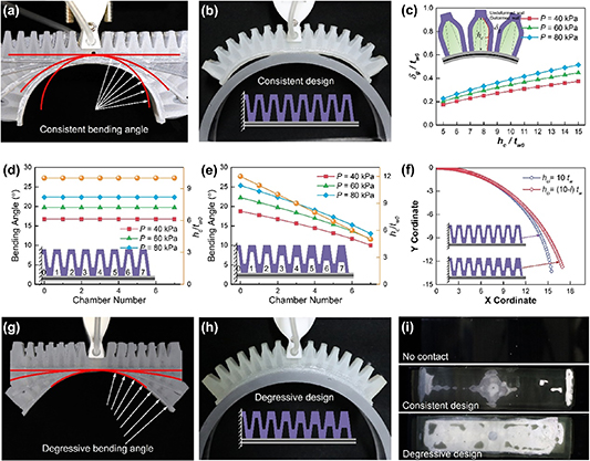
Figure 2. Bending behavior modeling and contact optimization of the soft adhesive gripper. Side views of (a) the bending sequences and (b) the contact states of the soft adhesive gripper with traditional consistent chamber design. (c) The calculated effects of chamber height on the deformation of the gap layer under various pressure conditions. Bending angle distribution of the actuator chambers with (d) consistent chamber height (traditional design) and (e) degressive chamber height (optimized design). (f) Bending trajectories of the actuator chamber with consistent chamber height and degressive chamber height, respectively. Side views of (g) the bending sequences and (h) the contact states of the soft adhesive gripper with optimized degressive chamber design. (i) The measured contact area distribution of the traditional and optimized soft grippers. Note that the white area reflects the real contact area for the FTIR method.
Download figure:
Standard image High-resolution imageTo this end, a parametric analytical model was established to predict and optimize the bending trajectory via structural modification [38–41]. The detailed modeling method and derivation process are provided in figure S3 and section S1 in the supporting information.
The calculated effects of the structural parameters on the bending behavior of the pneumatic actuator were fully described and analyzed in figures S4 and S5, and section S2 in the supporting information. Among these structural parameters, the chamber height has the best modulation effect to achieve the gradual rolling contact strategy. As can be seen from figure 2(c), the extension of the gap layer increases almost linearly with the chamber height increasing. Besides, it is more convenient to change the independent height of the individual chamber in contrast to other parameters. The traditional consistent chamber design of the actuator generates a consistent bending angle for all the inflated chambers, as shown in figure 2(d). In comparison, by designing a linearly degressive chamber height along the length direction of the actuator, the bending angle decreases with the chamber number, as can be seen from figures 2(e) and (g). The calculated bending trajectories of the whole actuator for consistent and degressive chamber height are plotted in figure 2(f), which directly shows the concept of the gradual rolling contact strategy. As can be seen from the contrast of figures 2(b), (h), and videos S1, S2, supporting information, the actuator with consistent chamber design easily rebounds from the substrate upon the increase of the positive pressure, while the one with degressive chamber design contact conformably with the substrate even at a large positive pressure. The resultant contact areas of these two situations were recorded with the frustrated total internal reflection (FTIR) method, as shown in the white zone of figure 2(i), where the top black photo is a control test without contact. The traditional consistent chamber design leads to a three-position poor contact (the center and the two ends), while the proposed linearly degressive chamber design achieves a relatively intimate contact condition. These results experimentally validated the gradual rolling contact concept, which also agree well with previous work from the view of torque distribution [33].
2.3. Grasping characterization and mechanism analysis
The soft adhesive gripper is brought to the substrate with a certain preload (figure 3(a)), followed by the inflation of the pressure chamber and vacuumizing of the vacuum chamber (figure 3(b)). Then it is retracted from the substrate, in which the maximum tensile force is regarded as the grasping force (figure 3(c)). The typical normal force and applied pressure curves in the grasping tests are shown in figure 3(d). Typical failure modes in the grasping tests were investigated at different negative pressures, as shown in figure 3(e). When the vacuum chamber is vacuumized to the maximum pressure differential, i.e. −100 kPa, the top of the soft adhesive gripper is fully stretched and retracted from the substrate with a sudden separation and a consequent cracking sound. It should be noted that the crack of the adhesive interface is initiated at the central loading area and rapidly propagated to the ends in the length direction, corresponding to the sudden drop of the peak force. When the negative pressure is −20 kPa, the gripper cannot hold such a large force, and the crack is generated from the width direction, followed by the peeling of the actuator in the length direction. When the negative pressure is not provided, the grasping force gets much lower, followed by a zigzag force curve fluctuation. This phenomenon is due to the multiple peeling occurring at the edges around the loading area and the two ends of the gripper, implying the severe uneven load distribution at the adhesive interface. The observed phenomenon and tested results indicate that the negative pressure in the vacuum chamber has a great effect on the load-sharing state among the micropillars and the consequent grasping force.

Figure 3. Characterization of grasping performances of the soft adhesive gripper. Schematics of the typical test procedures of the soft adhesive gripper including (a) approach without applying external pressure or vacuum, (b) contact by applying only pressure, and (c) grasp with both pressure and vacuum applied. (d) Typical test curves of the normal force and the applied positive pressure and negative pressure. (e) Typical grasping failure mode of the soft adhesive gripper under different negative pressure conditions. (f) The measured grasping force of the adhesive gripper under the optimal positive pressure and various negative pressure.
Download figure:
Standard image High-resolution imageThe effects of positive pressure on the grasping forces were first investigated, as shown in figure S6(a), supporting information. To achieve the maximal grasping forces, the negative pressure in these tests remained at −100 kPa. For substrates with a larger curvature radius, the gripper can easily make contact at a lower positive pressure. Therefore, the measured grasping forces are inverse to the curvature of the substrates at a low positive pressure range. As larger positive pressure will lead to the buckling of the soft actuator (see figure S6(b), supporting information), the grasping forces decrease for flat substrate due to poor contact. In contrast, with positive pressure and resultant bending angle increasing, substrates with smaller curvature radius tend to have incremental contact area and grasping forces (see figure S6(c), supporting information). Overall, there exists an optimal positive pressure for a specified substrate curvature, as both insufficient and excessive pressure will cause decreased contact area and resultant low grasping forces. After the optimal positive pressure was experimentally determined, the qualitative effects of negative pressure on the grasping forces of the soft adhesive gripper were systematically characterized.
As shown in figure 3(f), the grasping forces increase almost linearly with the negative pressure differential increasing, and the maximum is reached at the vacuum state, i.e. the negative pressure is −100 kPa. Moreover, this near-linear relationship holds for different substrate curvatures, as can be seen from the shadow area. This experimental result reveals that the grasping force strongly depends on the negative pressure regardless of the substrate curvature.
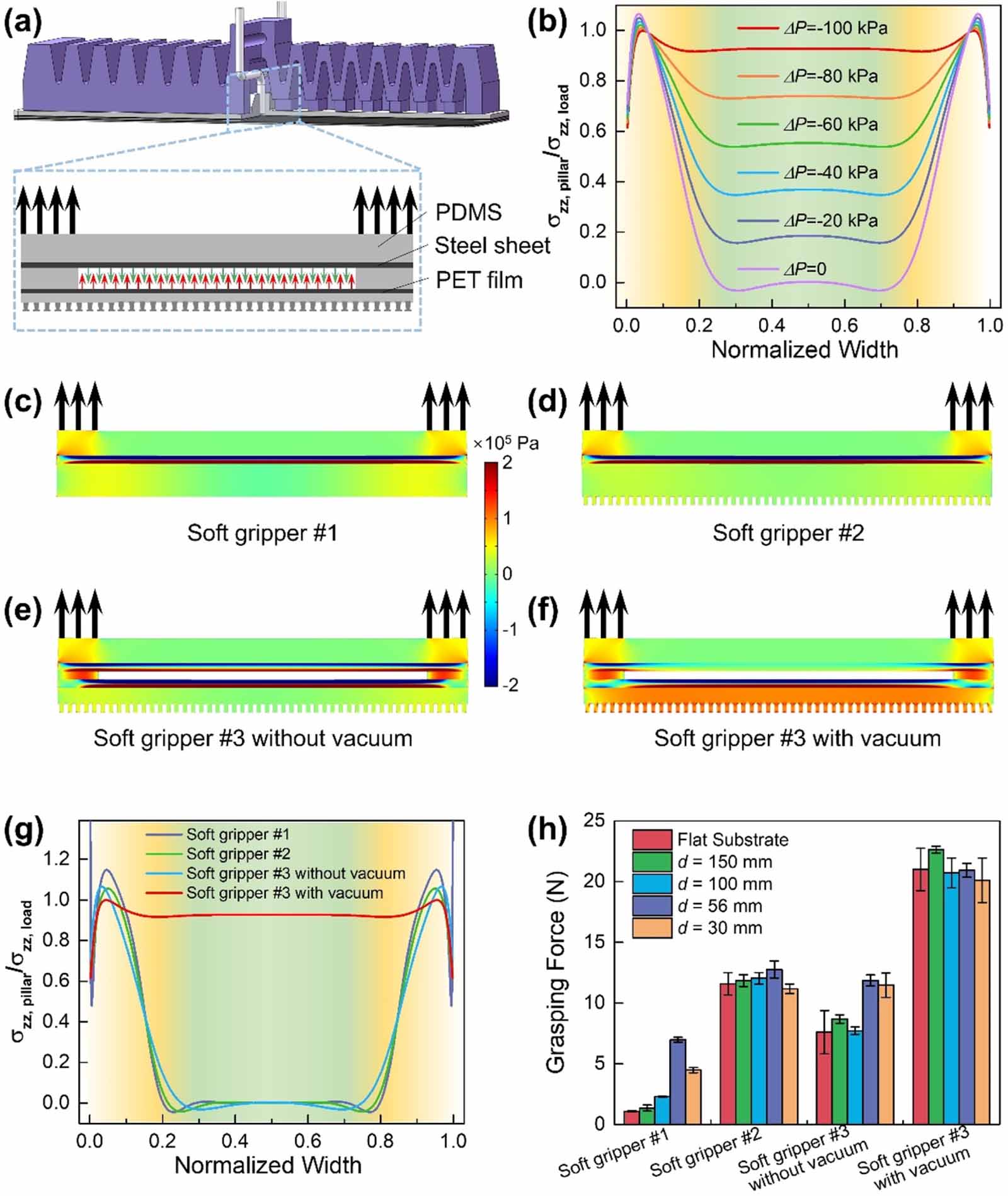
According to the typical failure analysis of the gripper at different negative pressures in figure 3(e), it can be basically deduced that the negative pressure in the vacuum chamber changes the load distribution at the adhesive interface, thereby changing the loading behavior during the retraction process and leading to the different grasping forces. To further explain the dependency of grasping forces on the internal negative pressure, FEM analysis was implemented to simulate the stress distribution among the contacted micropillars. Considering the complexity of the whole cross-scale model and the periodic features of the soft adhesive gripper, a simplified plain strain model extracted from the principal section of the gripper was established, as shown in figure 4(a). In the grasping process, the adhesive stress at the interface is transmitted through the micropillars, while the resultant load of the gripper is transmitted through the side wall, as indicated by the thick arrow. By changing the internal negative pressure acting in the vacuum chamber, the consequent stress distribution evolution along the width direction can be obtained as shown in figure 4(b). When the negative pressure is not applied, the adhesive layer is directly loaded from the ends of the side wall. As a result, the tensile stress at the two ends is much higher than that at the center, leading to the peeling of the adhesive layer from the width direction, consistent with the failure phenomenon. In this condition, the grasping force is equal to the peeling force at the two ends, which is low owing to the small bending stiffness of the vacuum chamber. In contrast, a high negative pressure differential will load the micropillars under the vacuum chamber, leading to a more uniform stress distribution. With the negative pressure differential increasing, the loading stress at the center also rises almost linearly, as can be seen from the incremental curves. Consequently, a higher negative pressure differential will load the micropillars more uniformly and transmit the stress effectively, thereby generating a larger grasping force. The simulated results agree well with the above experimental phenomena and results, theoretically demonstrating the equal load-sharing design of the vacuum chamber.

Figure 4. The equal load-sharing mechanism of negative pressure on the adhesion properties of the soft adhesive gripper. (a) Typical cross-section view of the simplified plane-strain schematic of the vacuum chamber. (b) The simulated effects of negative pressure on the normal stress distribution of the micropillars at the adhesive interface. The simulated normal stress (σzz ) nephograms of the bottom layers for (c) soft gripper #1 with a popular soft pneumatic actuator structure, (d) soft gripper #2 with directly bonded micropatterned adhesive layer, (e) soft gripper #3 proposed in this work with a vacuum chamber but no negative pressure, and (f) soft gripper #3 proposed in this work with a vacuum chamber and vacuum pressure. (g) The simulated normal stress distribution of the micropillars at the adhesive interface for different soft gripper construction. (h) The tested grasping forces of the four kinds of soft grippers on various substrates.
Download figure:
Standard image High-resolution imageTo further demonstrate the superiority of the proposed soft adhesive gripper with vacuum assisted adhesion effect, we theoretically and experimentally contrast four types of soft grippers with different bottom structures and loading conditions (figure S7, supporting information). Soft gripper #1 is a popular construction of soft pneumatic actuator with flat nonpatterned bottom layer. Soft gripper #2 is the same soft pneumatic actuator with directly bonded micropatterned adhesive layer. Soft gripper #3 and soft gripper #4 are soft adhesive grippers with a vacuum chamber connected adhesive layer proposed in this work, without and with applied vacuum pressure, respectively. It should be noted that all the bottom layers share the same total thickness and length for structural consistency. The simulated stress nephograms are shown in figures 4(c)–(f), which directly validates the proposed vacuum-assisted equal load sharing design. The extracted normal stress distribution among the micropillars and the actual grasping performances of these four soft grippers are further compared in figures 4(g) and (h), respectively.
As can be seen from figures 4(c)–(g), the first three types of soft grippers have an uneven normal stress distribution across the contact interface, which is caused by the end-dominated load transmission mechanism. Particularly, soft gripper #1 shows a stress singularity at the edges of the contact interface, due to lacking the contact splitting effect of micropatterned adhesive surface design [42]. In comparison, the vacuum-assisted equal load sharing design in soft gripper #4 is effective to improve the normal stress in the center area. As shown in figure 4(h), soft gripper #1 with flat nonpatterned bottom layer only exhibits a certain grasping capability (<8 N) on substrates with a relatively small curvature diameter (d = 56, 30 mm) via enclosed wrapping. As for substrates with larger curvature diameters (d > 100 mm), soft gripper #1 cannot wrap the substrates and it easily slips with a small friction force owing to the decreased normal force in the grasping process, resulting in a low grasping force of less than 3 N. For soft gripper #2, the strengthening effect of the directly bonded micropatterned adhesive surface is obvious, as the average grasping forces for all the substrates have been enhanced to ∼12 N. This is because the adhesive layer strengthens the interfacial loading capacity of both adhesion and friction. Nonetheless, soft gripper #3 with only a vacuum chamber presents a slightly poorer performance than soft gripper #2 on substrates with a large curvature radius. This result mainly arises from the fact that the bonded vacuum chamber has a thickness of ∼100 μm, which easily bends to affect the uniform contact of the micropillars. Besides, the bending stiffness of the laminated adhesive layer with PET backing is lower than the bonded adhesive layer with steel sheet backing, affecting the loading state in the tests [43]. Soft gripper #4 showed an enhanced grasping performance of over 20 N on all the substrates, as the vacuum pressure acts as the invisible loading transmission media for the central area. Overall, the simulation and experiments revealed the dual contributions of both the microstructures at the contact interface and the vacuum pressure modulated equal load sharing for load transmission on the enhanced grasping capacity of soft grippers.
2.4. Multifunctional performances and grasping demonstration
The grasping and releasing forces of the proposed soft adhesive gripper on various substrates were tested, as shown in figure 5(a). For the substrate with a curvature radius of 150 mm, the grasping force reached a maximum of 22.74 N, and the average grasping force on these substrates with various curvature radii ranging from 15 mm to infinity is over 20 N. In contrast, the average releasing force is about 2 N, owing to the symmetric boundary condition caused remaining contact area after peeling. The response time of the soft gripper for actuating the positive pressure (0.5 s), vacuum pressure (0.1 s), and the peeling retraction mechanism (0.8 s) were measured from the recorded data, respectively. Therefore, the maximal response time of the gripper for grasping and releasing is less than 1 s, as can be seen from figure 5(b). The grasping range and corresponding dominated working principles were also characterized by measuring the tangential circle diameter, as shown in figure 5(c). For substrates with a large curvature radius and even flat substrates, the soft adhesive gripper only needs a low positive pressure to achieve intimate contact for completing the grasping tasks. For substrates with smaller curvature radii or small-sized features, the soft adhesive gripper needs a high positive pressure to grip the objects. Considering the largest pressure-bearing capacity of the internal bonding interface, the gripper reaches the bending limit at a positive pressure of ∼120 kPa, corresponding to a grasping diameter of ∼20 mm. The dominant contributions of interfacial adhesion and friction to the total grasping force were divided as shown in the color regions of figure 5(c). When the positive pressure is less than 40 kPa, the grasping diameter is over 100 mm and the grasping force mainly originates from the interfacial adhesion. When the positive pressure is more than 70 kPa, the grasping diameter is less than 40 mm and the grasping force mainly originates from the interfacial friction. Within the range of the two demarcation points, both the adhesion and friction highly contribute to the total grasping forces. As shown in figure 5(d), the enhanced load capacity, fast response time, and extended grasping range were contrasted with previously developed soft grippers based on electro-adhesion [44–49], particle/layer jamming [21, 23, 50–52], SMPs [14, 53–55], and LMPAs [18, 20, 56], exhibiting the superiority of the proposed strategy.
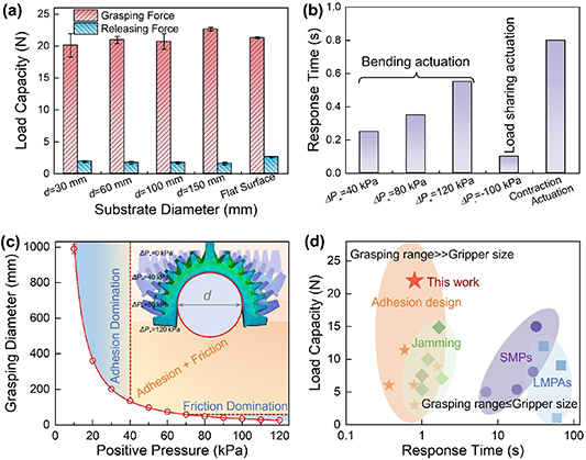
Figure 5. The controllable grasping capability and grasping range of the soft adhesive gripper. (a) The measured grasping forces and releasing forces of the gripper on various substrates. (b) The response time of the gripper for actuating the pressure chamber, vacuum chamber, and the reversibly bendable retraction mechanism. (c) The grasping range of the gripper by measuring the tangential circle diameter and corresponding domination mechanisms. The inset shows simulated bending states of the gripper under different positive pressures. (d) The extraordinary grasping performance of the proposed soft adhesive gripper in comparison with other soft pneumatic gripper based on variable stiffness method.
Download figure:
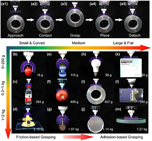
Standard image High-resolution imageFinally, the soft adhesive gripper was mounted as the end effector of an industrial robot (IRB 120, ABB) to perform actual grasping and manipulation tasks. As illustrated by a typical working cycle shown in figure 6(a) and video S3, supporting information, the grasping and transferring demonstrations were carried out for objects with different sizes, shapes, and weights. Like traditional soft pneumatic grippers, this soft adhesive gripper can utilize friction force to grasp objects with small volume and low weight. For example, it can easily grip cherry tomatoes weighing only 16 g and staplers weighing 110 g. More importantly, the interfacial friction force was significantly enhanced by adding the micropatterned adhesive surface. Consequently, the gripper is also able to stably grasp a bottle filled with water weighing 384 g, a smooth steel rod weighing 1.1 kg, and suction cup handles weighing up to 2.1 kg, which directly exhibits the strengthened grasping capacity.
Figure 6. Demonstration of using the soft adhesive gripper for grasping various curved and flat objects with a broad range of shapes, weights, and sizes. (a) The typical sequences of the gripper grasping, manipulating, and transferring a curved object like a packaging tape. The soft adhesive gripper utilizes friction force to grasp objects with small volume and low weight such as (b) cherry tomatoes, (c) water bottle, (d) suction cup handles, (e) staplers and (g) steel rods. It can also utilize both interfacial adhesion and friction to handle objects with medium sizes and moderate weights, such as (f) tomatoes, (h) light bulbs, (i) packaging tapes, and (j) PDMS storage bucket. It can also utilize mainly adhesion to grasp flat objects with larger curvature radius, such as (k) dust-free paper boxes, (l) books, and (m) glass plates.
Download figure:
Standard image High-resolution image
Benefiting from the enhanced interfacial adhesion and friction, this gripper can also handle objects with medium sizes and moderate weights. Even if the gripper cannot grip or hold objects with larger sizes, it can still grasp the objects by utilizing both interfacial adhesion and friction. The gripper can grasp spherical objects such as fragile light bulbs (58 g), soft tomatoes (406 g) and cylindrical objects such as a flexible packaging tape (457 g) and a rigid PDMS storage bucket weighing up to 1.1 kg. Distinguished from the multi-finger gripping mechanism of traditional soft pneumatic grippers, this gripper can also grasp smooth and flat objects, extending the grasping range of robotic grippers with a unique configuration. This gripper can grasp flexible dust-free paper boxes (155 g), side surface of books (760 g), and fragile glass trays weighing up to 1.2 kg. These experimental demonstrations convincingly proved that our proposed soft adhesive gripper based on controllable adhesion can use both interfacial adhesion and friction to reliably grasp objects with different sizes, shapes, masses, and materials, validating the high load capacity and board grasping versatility of this effective soft robotic gripper design. All of the demonstrations shown in figure 6 were conducted using the same gripper without any additional adjustments or surface material changes, thereby manifesting the robustness of this mechanism. While the durability limitation of adhesive surfaces may lead to a gradual decline in grasping performance after hundreds of uses (decreased by about 10% after 200 uses), it can be completely restored by replacing the adhesive material.
3. Discussion
3.1. Contact conformability and equal load sharing
Intimate contact and equal load sharing across the contact interface are key to enhancing the load capacity of a gripper by fully utilizing interfacial adhesion and friction [29, 31, 35, 36, 57]. The proposed rolling contact strategy enabled by the degressive chamber design realized gradual contact on various curved substrates, which effectively increased the real contact area. Therefore, the gripper was able to generate enough adhesion force for objects with large curvature radius (figures 6(h)–(m)) and friction force for objects with small curvature radius (figures 6(d) and (g)), respectively. This is an important fundamental to achieving high load capacity for objects of a broad range of sizes and shapes. The equal load-sharing design assisted by the vacuum chamber is effective in enhancing the adhesion force by integrating the adhesive stress across the contact interface, especially for objects larger than the gripper size (figures 6(i)–(m)). It should be noted that the equal load sharing concept also works for objects with a small size (figures 6(d) and (g)), as the enhanced friction force generated by the micropatterned adhesive surface is mainly transmitted to the load cell through the embedded inextensible steel sheet. Based on the above two equal load-sharing designs, this gripper can achieve a high load capacity of over 20 N on various smooth surfaces with diverse curvature radii, as can be seen from figures 5(a) and 6. The gripper can also perform well with rough objects with small curvature radii through the wrapping mechanism. However, for surfaces with large curvature radii, the performance of the gripper on the rough surface is significantly worse than that on the smooth surface, which is caused by the negative effect of surface roughness on microscopic conformability between the dry adhesion surface and the target surface.
Previously reported controllable stiffness methods to enhance load capacity often requires a relatively long modulation time, an extra heating circuit, and a complex control system. Besides, the increased stiffness also increases the inevitable risks of damaging fragile objects. In comparison, the proposed strategy realized high load capacity via strengthened interface design without adding extra electrical components or sacrificing the intrinsic soft properties. The whole gripper is made of soft materials except the embedded flexible thin steel sheet and PET film, which does not obviously affect the soft performance. It should also be noted that the steel sheet is selected as the inextensible layer owing to its high elastic modulus, which can enhance the load-sharing performance for adhesion and friction with a larger bending stiffness and tensile stiffness [43, 58]. The coupled roughed PET film is necessary to isolate the contact between the steel sheet and the soft adhesive membrane, as the soft membrane easily forms adhesive contact under vacuum pressure, which will cancel the vacuum-assisted equal load-sharing effect. Whereas, the rigid steel sheet and PET film easily remain in microscopic point contact under the pressure differential of 100 kPa, which ensures the vacuum-assisted load sharing across the entire vacuum chamber. The tested grasping forces for the steel sheet-PET film design and the steel sheet-soft membrane design also validated this indispensable inner design of the vacuum chamber, as shown in figure S8, supporting information.
3.2. Fast responses for grasping and releasing
As can be seen from figure 5(d), the fast response time (<1 s) of the gripper by mechanically actuating pressure and tendons outperforms other methods such as temperature modulation (dozens of seconds). Moreover, the actuation of the positive pressure and vacuum pressure could be further accelerated by using a larger compressor and pump with higher pressure differential and developing well-designed proportional-integral-differential algorithms for pressure control. In this design, detachment actuation determines the limit of the response time. Peeling is the most effective mechanical modulation strategy for detachment of large-area isotropic adhesive surfaces. For objects with a large curvature radius especially flat surfaces, the stored bending strain energy is not enough to overcome the adhesion work of the contact interface. Therefore, the contraction mechanism was designed to bend the actuator outward to peel the adhesive surface from the substrate for easy detachment. To protect the motor and the actuator, the actuating time of the servo motor was manually set to 0.8 s. In fact, the maximum rotate speed of the servo motor is ∼100 rpm, resulting in a contraction speed of ∼50 mm s−1 for the tendon reel. The total gap length between the chambers is around 21 mm, leading to a limited response time of ∼0.4 s for releasing. Overall, this gripper can achieve a fast-response performance in actual pick and place applications.
3.3. Multimodal grasping functionality and high load capacity
Thanks to the conformable adaptability of the optimized bulk actuator and the strengthened interfacial adhesion and friction, this soft adhesive gripper exhibits versatile grasping performances such as warping, gripping, and sticking for a wide variety of objects with diverse shapes and curvature radii. The gripper can grasp small objects within the feasible range of the gripper as traditional soft pneumatic grippers. More importantly, it can also grasp objects with a much larger size than that of the gripper, as shown in figures 6(j)–(m). This unique feature significantly expands the grasping adaptability and improves the grasping universality of the gripper. For traditional multi-finger grippers, the fingers need to be customized to fit the object size, which is cumbersome for multiple grasping tasks of different-sized objects. For the proposed gripper, it is much easier to accomplish such challenging tasks with the existing gripper configuration. It is worth mentioning that this concept could also be utilized for underwater environments by integrating adhesives capable of providing underwater adhesion, which may overcome the water lubrication-induced slippery grasping problem [59–61]. Through modifications in gripper dimensions and the incorporation of advanced sensing and control techniques, this design can be adapted for the delicate manipulation of fragile items. The proposed soft adhesive gripper combining bulk actuator design and interfacial adhesion design provides novel insights for the field of soft robotics to develop more universal, versatile, and powerful robotics.
4. Conclusion
In summary, we present a versatile soft adhesive gripper with enhanced load capacity and expanded grasping adaptability by fully utilizing interfacial adhesion and friction of the micropatterned adhesive surface. The soft adhesive gripper can compliantly attach to curved substrate with the rolling contact strategy after optimizing the structural design of the pneumatic bending actuator. By utilizing the vacuum pressure as the invisible force transmission media, the equal load-sharing condition of the contact interface was significantly improved. Therefore, it can reach a grasping load capacity of over 20 N on smooth substrates with various curvature radii ranging from 15 mm to infinity (flat substrate). It should also be noted that the original compliance fully remained as the bottom layer only added several flexible layers. Moreover, the soft adhesive gripper was integrated into a robotic arm to grasp objects with diverse material components, various surface shapes, and different weights, which demonstrated broad object adaptability and high load capacity. This work focuses on strengthened interfacial adhesion to enhance the grasping performance of soft robotic grippers, which presents a new strategy for developing soft grippers with multifunctional and powerful capabilities of grasping and manipulation.
5. Experimental section
5.1. Fabrication of the soft adhesive gripper
The detailed fabrication procedures are schematically illustrated in figure S1, supporting information. The soft actuator with positive chambers was obtained by casting in 3D-printed two-part molds, which were designed using Solidworks 2018 (Dassault Systemes SolidWorks Corporation). After drying in an oven at 60 °C for 12 h to remove the curing inhibition components, the two-part molds were carefully aligned and assembled with specified metal bars to create the external loading hole, the tendon contraction holes, and the external channels for mounting pressure and vacuum tubes. The two-part Polydimethylsiloxane (PDMS, Rubber Molding Material Corporation, China) was mixed with a 1:1 weight ratio, degassed in a vacuum box, injected into the assembled molds, and cured in an oven at 60 °C for 2 h. After the soft actuator was fully cured, it was carefully demolded from the disassembled molds. In the meanwhile, the soft bottom layer was cast and demolded from an open mold, followed by assembling of the vacuum tube. A PET film with a thickness of ∼100 μm was cut with a graver. A thin steel sheet with a thickness of ∼100 μm was cut off using wire cutting method, which is 2 mm narrower than the soft bottom layer in the length and width directions, respectively. The prepared steel sheet and PET film were grinded with an abrasive paper, cleaned with alcohol, and pretreated by immersing in a primer (Dow Corning PR-1200 RTV Prime Coat) for 2 h to enhance the bonding performance. The micropatterned adhesive layer was replicated on the PET film with a common molding technique. Mushroom-shaped micropillars are composed of a cylindrical stalk with a 40 μm diameter, an 80 μm height, and a top circular plate with a 2 μm thickness and a 45 μm diameter, distributing hexagonally on the adhesive layer with a 60 μm center distance.
After drying in the air, the steel sheet was then coated with a ∼100 μm thick silicon adhesive film (Sil-Poxy, Smooth-On Inc., USA) on a film coater (TC-100, Mitsui Electric Seiki Co., Ltd, Japan), followed by sticking to the lower surface of the soft bottom layer. After the bonding layer is cured, the exposed surface of the steel sheet was covered with a 100 μm thick adhesive tape, followed by coating the silicon adhesive (Sil-Poxy, Smooth-On Inc., USA) at the margin of the steel sheet. After the adhesive tape was carefully removed, a thin adhesive layer around the steel sheet was formed. Then the soft bottom layer and the prepared adhesive layer were quickly bonded together at the remained edges with a width of ∼2 mm, which forms a sealed ultra-thin vacuum chamber between the steel sheet and PET film. After the vacuum chamber was fully cured, it was bonded to the soft actuator, followed by the sealing between the tubes and the soft actuator. Finally, the retraction mechanism and the mechanical components were assembled. The retraction mechanism was actuated by a servo motor (Yinyan Model Tech, Ltd, China) with a rated torque of ∼0.2 N·m. The soft adhesive gripper is supported by a 3D-printed flange via the loading bar, which can connect to the load cell and the robotic arm end.
5.2. Experimental setup and grasping performance characterization
Grasping performances were tested on a customized grasping measurement setup as shown in figure S2, supporting information. The customized apparatus is made up of a motion module, a clamping module, a pressure control module, and a data acquisition module. The motion module is a motorized stage (OSMS(CS)26–100(X), SIGMAKOKI, Tokyo, Japan) with a minimum resolution of 0.5 μm. The soft adhesive gripper was connected to a load cell (LDCZL-BF, LOADING SEN, China) with a resolution of ∼0.1 N mounted on the motion module. The clamping module consists of two clamps to fix the curved substrates. The pressure control module consists of a positive pressure channel and a negative pressure channel. The positive pressure control channel is made up of an air compressor, a reducing value, an electro-pneumatic proportional pressure valve (ITV0030, SMC Inc., Japan), and a pressure sensor (PSE531, SMC Inc., Japan). The negative pressure control channel is made up of a vacuum pump, an electro-pneumatic proportional pressure valve (ITV0090, SMC Inc., Japan), and a pressure sensor (PSE532, SMC Inc., Japan). The load cell and two pressure sensors were connected to a data acquisition device (USB 6002, National Instruments, USA) to obtain the real-time force and pressure data. In the experiment, silica glass plate with different curvature radii were used as the counter substrates. The contact area was measured using FTIR method, in which a light emitting diode was mounted at the side of the substrate to illuminate the real contact region. The soft adhesive gripper was brought into contact with the substrate at a constant velocity of 10 μm s−1 until a specified preload was reached. Then the contact state was held for 10 s, followed by the retracting of the soft adhesive gripper at a constant velocity of 10 μm s−1 until total detachment. For the releasing of the gripper, the retraction mechanism was actuated before retraction. The maximum tensile force in the retraction process without/with retraction mechanism actuation were defined as the grasping force and releasing force, respectively. All the experiments were performed for at least three times and the mean values and standard deviation were recorded as the results.
5.3. FEM simulation
The FEM simulation for the bending process of the soft adhesive gripper was conducted in Abaqus/Standard (Abaqus 2018, Providence, RI, USA) owing to its superior nonlinear solver. The structural and materials parameters in the simulation were kept the same as those of the designed protypes. The elastomer was assigned with an elastic modulus of 3 MPa and Poisson ratio of 0.49 by utilizing an incompressible hyperelastic Mooney–Rivlin model. The loading area was assigned with a fixed constraint while the inner wall surfaces of the chambers were assigned with prescribed normal pressure to actuate the gripper.
The FEM simulations for the load sharing of the micropillars were performed using plane strain models in COMSOL (COMSOL Inc., Burlington, MA, USA) owing to its superiority of parametric modeling. The geometrical and mechanical properties were kept the same as the design parameters. A flat glass plate was modeled as the substrate with a fixed constraint. Prescribed stresses of 100 kPa was assigned to the side walls of the chamber to simulate the loading state. The interfacial contact and adhesion were simulated with the cohesive zone model using a penalty method. The tensile stresses extracted from the micropillars were measured across the interface to show the normal interfacial stress distribution.
Acknowledgments
This work was supported by the National Natural Science Foundation of China under Grant U2141248.
Data availability statement
All data that support the findings of this study are included within the article (and any supplementary files).
Supplementary information (2.5 MB DOCX)
Supplementary video S1 (4.4 MB MP4)
Supplementary video S2 (5.8 MB MP4)
Supplementary video S3 (21.0 MB MP4)