

Abstract
Increasing photoactive areas and oxygen vacancy to improve the separation and utilization of electrons and holes in a photocatalytic process are a guarantee for highly photocatalysis efficiency. In this work, we report a CAs@B-TiO2 core–shell nanospheres via a nanoscale water spray assisted method to deposit of black titanium dioxide (B-TiO2) on carbon aerogel sphere (CAs) though slowly hydrolyzing of butyl titanate (e.g. TBOT) in an ethanol-water system. On this basis, furthermore, a facile one-step N2H4 · H2O treatment was used to introduces oxygen vacancies on the surface of TiO2 coating layer forming black TiO2. Oxygen vacancies can extend the optical response range of the TiO2 shell from the ultraviolet to the visible region, and increase conductivity and charge transport on the interface of core–shell structure. This study reveals the importance of surface oxygen vacancies for reducing band gaps and developing highly active photocatalysts under visible light.
Export citation and abstract BibTeX RIS
1. Introduction
The continuous development of industrial engineering will produce lots of organic waste such as tannic acid (TA), polychlorinated biphenyl and aromatic amines which will cause serious environmental pollution [1]. To date, TiO2 has been widely used in photocatalytic environment cleaning, H2 production, and solar cells. Since 1972, when Fujishima and Honda reported that TiO2 had good photocatalytic effect under ultraviolet light irradiation, great efforts have been devoted to the exploration of highly efficient and stable photocatalytic materials [2, 3]. Due to its good stability, non-toxicity, low price, easy regeneration and recycling, TiO2 has been widely studied in photocatalysis [4]. The latest researches showed that photocatalytic oxidation technology has been turned into a mainstream technology for organic pollutants treatment due to its environmentally friendly, plain course of reaction and suitable degradation capability [5, 6]. Whereas, the photocatalytic activity of TiO2 subject to its wide-band gap and low specific surface area, which greatly reduces the photocatalytic degradation performance under visible light irradiation [7]. In consequence, the catalytic performance of pure TiO2 particles cannot satisfied the practical needs, which badly restricts its practical application [8].
It is a versatile method to dope metal and non-metal elements into TiO2 to shorten the band gap width to expand the absorption of light into the visible areas [9]. Whereas, the issues like increasing recombination of electron–hole pairs and reduced electron conversion efficiency (ECE) of UV light reflect the significant limitations of this approach [10–12]. Therefore, in order to further improve the photoelectrochemical activity of TiO2, a credible strategy is to settle the reduction of ECE in the ultraviolet-visible area and increase the photoactive area [13]. Oxygen vacancies have been reported to play a key role in determining the surface and electronic properties of TiO2. It is known that oxygen vacancies (Ti3+) make TiO2 with excellent catalytic activity under visible light [14]. The introduced oxygen vacancies produce a local reaction in the band gap, expanding the light absorption region. In addition, the reported methods for producing reduced TiO2 are mainly based on atmospheric pressure chemical vapor deposition and energetic particles (electron, laser or Ar) bombard [15, 16]. Whereas, these approaches require rigorous synthetic facilities that limit their practical application. Most recently, Zhang et al reported an oxidation strategy for reducing Ti4+ to Ti3+ by reducing atmosphere (H2O/H2) [17]. Nevertheless, it is difficult to avoid introducing foreign-bod into the TiO2 crystal lattice [18]. Therefore, exploiting a facile and reliability method to prepare a steady reduced TiO2 photocatalyst with a suitable local state remains a significant challenge [19, 20].
In addition to changing the morphology of TiO2, it is equally important to improve the valency to form oxygen vacancies to enhance optical absorption [21]. The TiO2 shell supporting on a core with large specific surface area and good dispersibility is considered as an effective structure for increasing photoactive contact surface [22, 23]. The excellent specific area, favorable direction and homogeneous interface structure significantly increase the optical absorption depth [24]. The separation of charge is enhanced by shortening the transmission distance of the charge carriers [25, 26].
Besides, N2H4 · H2O is a safe and commonly used reducing agent with high reducing ability to reduce Ti4+ to Ti3+ [27, 28]. The reaction is as follows:


In this study, a layer of partially reduced B-TiO2 was loaded on the surface of carbon aerogel (CAs) by nano-water spray assisted method to form CAs@B-TiO2, which shows a high activation of tannin degradation under visible light. The N2H4 · H2O treatment introduces oxygen vacancies on the surface and interior of TiO2 to form B-TiO2. Oxygen vacancies can enhance the photocatalytic activity of TiO2 and increase conductivity and charge transportation under visible light irradiation. And the B-TiO2 loading on the CAs will significantly increase the oxygen vacancy density, thereby enhancing conductivity and charge transport.
2. Experimental section
2.1. Chemical reagents
Tetrabutyl titanate (TBOT), 97%, CA microspheres, ammonium hydroxide, NH4OH, 28%, N2H4 · H2O, 80%, NaOH and TA, ethanol, nitric acid, HNO3, 36%. All these reagents were used without additional treatment. Deionized water with a medium purity conductivity of less than 1 us cm−1.
2.2. Synthesis of CAs@B-TiO2
1 g CAs was dispersed in weak nitric acid solution by magnetic stirring. Then, 20 ml nitric acid was added to make CAs better dispersed in liquid system. After sufficiently mixing, the solution is washed several times to become neutral and dried overnight at 60 degrees to get treated-CAs. 0.4 g of treated-CAs powder was added into 100 ml ethanol. Then slowly add various quantity of TBOT with intensively stirred for 4 h to get CAs@TiO2. Then, 20 ml N2H4 · H2O was added to the mixture and the rate of hydrolysis was controlled by a nanoscale water sprayer [29, 30]. The prepared photocatalysts were laved with deionized water and ethanol. The different sample ratios are showing in table S1 is available online at stacks.iop.org/NANO/32/285601/mmedia.
2.3. Characterizations
Morphological characteristics of CAs@B-TiO2 were measured by high resolution cold field emission scanning microscopy (SEM, Leica Cambridge UItra 55). The elemental mapping of the energy dispersive x-ray spectrum was used to confirm the surface elements of CAs@B-TiO2. The x-ray photoelectron spectra (XPS) were taken using an AM CSFG 3600 electron energy spectrometer [31]. The specific surface area was measured by Brunauer–Emmett–Teller (BET) method [32].
3. Result and discussion
3.1. Preparation and characterization of CAs@B-TiO2
The preparation process of CAs@B-TiO2 under constant magnetic stirring assisted by nanoscale water spray is showing in figure S1 [33]. During the CAs@TiO2 preparation process, nanoscale water spray provide uniform water nano-mist, which is controllable for the formation of TiO2 [34, 35]. Then, the B-TiO2 shell was prepared by hydrazine hydrate reduction [36]. This simple method can not only saved the high cost of preparation, but also avoided the explosion risk of the hydrogenation process. In addition, B-TiO2 as a shell of CAs synthesized by liquid phase, has more controllable homogeneity. The physical appearance of the as-prepared CAs@B-TiO2 nanomaterials powder is shown in figure S2.
The morphology of CAs is revealed by SEM (figures 1(a), (b)), which clearly shows that CAs have good sphericity and good dispersion. The average diameter of microspheres is about 6 μm. SEM scanning of CAs@B-TiO2 shows that the B-TiO2 shell was successfully coated on CAs microspheres (figure 1(c)). It is clearly exhibited from figures 1(c), (d) that the TiO2 shell is evenly supported on the surface of CAs [37]. And under magnetic stirring, the TiO2 shell layer loaded on the CAs microspheres is slightly flaw [38].

Figure 1. (a), (b) SEM images of CAs and (c), (d) CAs@B-TiO2.
Download figure:
Standard image High-resolution imageFor the sake of further verify the B-TiO2 shell was successfully loaded on the CAs microspheres' surface, the EDS-mappings of CAs@B-TiO2 are performed. As shown in figure 2, the C, N, O, Ti are well-distributed [39]. The outline of Ti-element distribution in the figure 2(e) suggests the valid loading of TiO2 on the CAs surface.

Figure 2. EDX-mapping images of CAs@B-TiO2.
Download figure:
Standard image High-resolution imageFigure 3(a) shows that CAs@B-TiO2 have single crystal electron diffraction spot. The lattice fringes can be clearly observed from high resolution transmission electron microscope (HRTEM), which reveals the nanocrystalline of CAs@B-TiO2 with lattice spacing of 0.35 nm (figure 3(b)), corresponding to the (101) plane of anatase TiO2. The XRD patterns further suggest the excellent crystallinity of CAs@B-TiO2, and the anatase is the dominated plane (figure 3(c)). Figure 3(d) shows the Raman spectra of TiO2 and CAs@B-TiO2. The Raman spectra suggests that the structure of CAs@B-TiO2 is almost the same as pure anatase TiO2 but with little blue shift. The slight blue shift of CAs@B-TiO2 can be attributed to the formation of TiO2−X on the surface of B-TiO2.
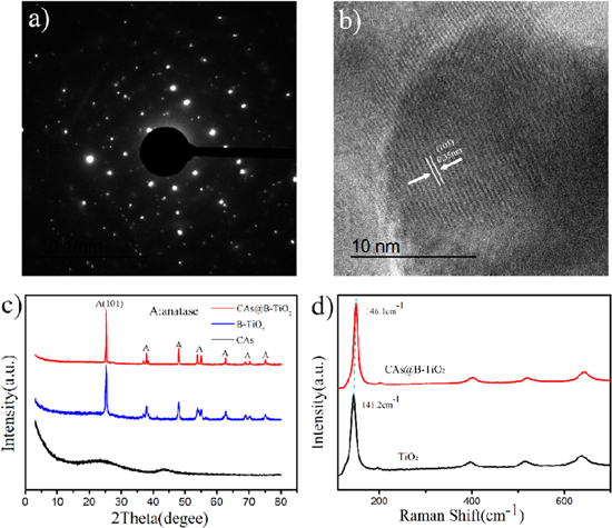
Figure 3. (a) Single crystal electron diffraction pattern of CAs@B-TiO2, (b) HRTEM images of CAs@B-TiO2, (c) XRD patterns of CAs, B-TiO2, CAs@B-TiO2, (d) Raman spectra of pristine TiO2 and CAs@B-TiO2.
Download figure:
Standard image High-resolution imageThe CAs with large surface area can acts as a carrier for the dispersion of B-TiO2. Figures S4(a), (b) show the BET and BHJ curves of CAs, respectively. As the shown in figure 3(a), the N2 isothermal adsorption curve is of type I was calculated to the BET surface area of CAs@B-TiO2 is 995.5070 m2 g−1 [40]. The mesoporous channels mainly distributed around 5 nm, which do not hinder the diffusion of TA molecules [41]. The large specific surface area and suitable pore distribution can enhance the contact between CAs@B-TiO2 and TA, thus providing facilitate for photodegradation of TA by CAs@B-TiO2. The XRD patterns shows that CAs@B-TiO2 possesses better crystallinity and mainly exhibits anatase crystal form (figure 4(c)) [42].
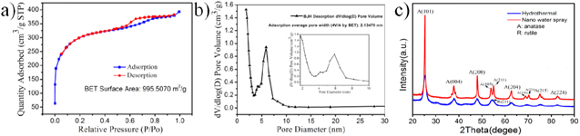
Figure 4. (a) Nitrogen adsorption/desorption isotherms of CAs@B-TiO2, (b) the corresponding pore size distribution curve of CAs@B-TiO2 and (c) XRD patterns of CAs@B-TiO2.
Download figure:
Standard image High-resolution imageThe Ti, O and C peaks are clearly recorded in the XPS survey spectra of CAs@B-TiO2 (figure S7(a)). The C 1s XPS spectrum shows four characteristic peaks at 284.7 eV, 285.1 eV, 286.2 eV, and 288.9 eV, which are belong to C–C, C=O, O=C–O, and C–O, respectively (figure S7(b)). This indicated that the surface of CAs was partially oxidized during nitric acid treatment to form oxygen-containing functional groups such as carboxyl group and hydroxyl group [43, 44]. In the O 1s spectrum, the peak at 530.8 eV was corresponding to the Ti=O in TiO2, together with the peak at 532.1 eV attributed to the oxygen vacancy (figure 5(b)) [45]. The enhanced area of the peak at ∼532.1 eV in CAs@B-TiO2 suggests that the concentration of oxygen vacancy in CAs@B-TiO2 are much higher than that of pure TiO2. The Ti 2p3/2 and Ti 2p1/2 corresponding to TiO2 are located at 459.8 eV and 465.7 eV, respectively (figure 5(c)). The peaks of Ti 2p in CAs@B-TiO2 were shifted to lower binding energy compared with the same peaks for pure TiO2. This small shift likely resulted from the presence of additional oxygen vacancy and Ti3+ in CAs@B-TiO2 [46]. The binding energies of Ti are consistent with other reported values of B-TiO2. The slight N peak is due to the defect in CAs caused by nitric acid treatment (figure S7(d)).

Figure 5. (a) XPS spectra of CAs, B-TiO2 and CAs@B-TiO2, (b) Ti 2p and (c) O 1s spectra of TiO2 and CAs@B-TiO2.
Download figure:
Standard image High-resolution imageThe defect level of pristine TiO2, B-TiO2 and CAs@B-TiO2 were verified through the UV/Vis spectra. Owing to the oxygen vacancy, the photoexcitation energy of the valance band to the defect level is reduced. As a result, CAs@B-TiO2 shows enhanced absorption in all bands of the spectrum (figure 6(a)). Benefits from the oxygen vacancy facilitating charge transfer, the electrons in the defect energy level can be transferred easier than the electrons in the conduction band. The narrow band gap width indicate that the CAs@B-TiO2 responds to a wide range of wavelengths of visible light, thus the CAs@B-TiO2 achieves higher light utilization to generate more holes (figure 6(b)).
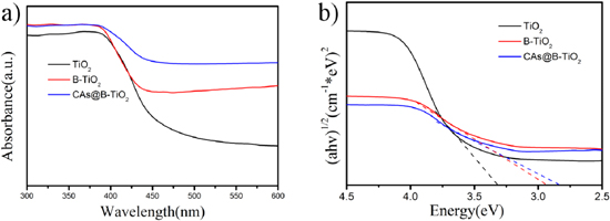
Figure 6. (a) UV/Vis diffuse reflection spectra of pristine TiO2, B-TiO2 and CAs@B-TiO2. (b) Plots of (α hv)1/2 versus the photon energy (hv).
Download figure:
Standard image High-resolution imageThe main function of CAs is to provide a carrier for B-TiO2, increasing its dispersion and photoactive area. The oxygen vacancies on B-TiO2 are mainly formed during the H2 gas sintering process. The resistance of the catalyst decreases, the conductivity increases, and the charge transport performance increases. To support this statement, impedance data was added to the manuscript. It can be seen from figure 7(a) that the impedance of CAs@B-TiO2 is the smallest. We can see from figure 7(b) that the photocurrent of CAs@B-TiO2 has increased significantly when the light is turned on.
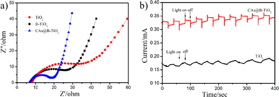
Figure 7. (a) EIS spectroscopy and (b) photoelectrochemical.
Download figure:
Standard image High-resolution image3.2. Photocatalytic activities
The photodegradation capability of CAs@B-TiO2 to TA under simulated solar irradiation was evaluated. The photocatalytic activities of nano-TiO2 and a series of CAs@B-TiO2 were demonstrated by degrading TA in the simulated wastewater (figure 8(a)). Under the dark reaction condition, CAs@B-TiO2 showed a weak adsorption of TA (about 20%), which is mainly attributed to the affinity of the carbon skeleton structure of CAs to organics [47]. Without any self-decompose, TA was photodegraded more than 90% by CAs@B-TiO2-30 in 40 min under the simulated solar irradiation. This result is mainly benefited from the coating of B-TiO2. Figure 8(b) shows the curve of TA concentration versus degradation time. Figure 8(c) shows the photodegradation curves of the different photocatalysts, in which CAs@B-TiO2 dominates the lower order. The fitting result suggest that the first-order kinetics of CAs@B-TiO2 (figure 8(d)).

Figure 8. (a) Photodegradation of TA by the TiO2, CAs@B-TiO2-10, CAs@B-TiO2-20, and CAs@B-TiO2-30, (b) original light degradation curve of CAs@B-TiO2-30, (c) different photocatalysts under irradiation at pH of 6.0 and temperature of 293 K and (d) fitted TA degradation process of different photocatalysts by the first-order kinetics. The initial concentrations of TA were 25 mg l−1.
Download figure:
Standard image High-resolution image3.3. Stabilization and reusability
Stability and recycling capacity are important indexes for evaluating photocatalysts. The CAs@B-TiO2 maintain 85% photodegradation capacity after being used for three times (figure 9). Limited by the inevitable mass and activity losses of the photocatalyst in the recovery process, the photodegradation capacity maintains 48% with the relative standard deviation of 1.72% after 10 cycles. This result suggests that CAs@B-TiO2 has good stability and is expected to be applied to real wastewater treatment.
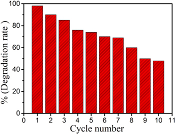
Figure 9. The effect of recyclability on the photocatalytic activity of catalyst.
Download figure:
Standard image High-resolution imageA scheme for photodegradation of TA by CAs@B-TiO2 was constructed (scheme
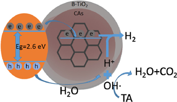
Scheme 1. The mechanism of photodegradation of TA by CAs@B-TiO2.
Download figure:
Standard image High-resolution image
The titanium dioxide layer covering on the surface of CA core is made up of titanium dioxide nanoparticles with a diameter of about 10 m rather a titanium dioxide film structure. Therefore, the part of exposed CA would not hinder the contact between electrons and hydrogen ions.
4. Conclusions
In this work, the CAs@B-TiO2 core–shell microspheres were successfully synthesized by controlling the hydrolysis rate of TBOT via nanoscale water spray assisted strategy. The obtained B-TiO2 was anatase crystal form with good crystallinity loaded on the surface of CAs core. The core–shell structure achieves good dispersion, which is beneficial to the rapid degradation of TA. The experimental results show that CAs@B-TiO2 degrade 98.6% of TA into H2O and CO2 in 40 min under visible-light irradiation. We established a photodegradation scheme of TA by CAs@B-TiO2 and discussed the photodegradation mechanism. This study reveals the importance of surface oxygen vacancies for reducing band gaps and developing highly active photocatalysts.
Acknowledgments
This work was supported by the Natural Science Foundation of China(21976148); Basic Scientific Research Project of China (JCKY2018404C008); the National key research and development Project of China (2016YFC1402500); the Project of State Key Laboratory of Environment-friendly Energy Materials, Southwest University of Science and Technology (18zxhk04); the Long Shan Talent Project (18LZX304, 18LZXT04) and the Doctoral Foundation Project of Southwest University of Science and Technology (Grant No. 18zx7148). Supported by Postgraduate Innovation Fund Project by Southwest University of Science and Technology (19ycx0014).