
Abstract
During the last decade, graphene foam emerged as a promising high porosity 3-dimensional (3D) structure for various applications. More specifically, it has attracted significant interest as a solution for thermal management in electronics. In this study, we investigate the possibility to use such porous materials as a heat sink and a container for a phase change material (PCM). Graphene foam (GF) was produced using chemical vapor deposition (CVD) process and attached to a thermal test chip using sintered silver nanoparticles (Ag NPs). The thermal conductivity of the graphene foam reached 1.3 W m−1 K−1, while the addition of Ag as a graphene foam silver composite (GF/Ag) enhanced further its effective thermal conductivity by 54%. Comparatively to nickel foam, GF and GF/Ag showed lower junction temperatures thanks to higher effective thermal conductivity and a better contact. A finite element model was developed to simulate the fluid flow through the foam structure model and showed a positive and a non-negligible contributions of the secondary microchannel within the graphene foam. A ratio of 15 times was found between the convective heat flux within the primary and secondary microchannel. Our paper successfully demonstrates the possibility of using such 3D porous material as a PCM container and heat sink and highlight the advantage of using the carbon-based high porosity material to take advantage of its additional secondary porosity.
Export citation and abstract BibTeX RIS

Original content from this work may be used under the terms of the Creative Commons Attribution 4.0 license. Any further distribution of this work must maintain attribution to the author(s) and the title of the work, journal citation and DOI.
1. Introduction
Due to the increasing demand for more functions and improved performances, while continuing the miniaturisation of systems and components, heat dissipation is of critical importance for the electronics components and systems. More specifically, many electronic components are subjected to intermittent and periodic pulsed thermal loads that might seldomly be exposed to extreme conditions. A practical solution to protect the electronic systems under these periodic and harsh conditions is through implementing a non-steady state system of the metallic component in combination with an organic phase, in a configuration to optimise the contact efficiency and homogeneity between the two components [1]. Consequently, the system of the metallic and the organic phases can provide sufficient cooling capacity during the pulsed load with high thermal conductivity of the former and dissipating that heat before the onset of heat absorption in the latent energy of the latter.
Organic phase change materials (PCMs) such as paraffin have been widely investigated as high latent thermal energy storage material capable of absorbing/releasing energy loads while being affordable, chemically stable and nontoxic with a low vapour pressure [2]. However, the low thermal conductivity of the organic paraffin PCM (e.g. ∼0.2 W m−1 K−1) was found to hinder its direct integration in the electronic packaging strategy. In order to address the thermal conductivity issue of paraffin, two main approaches based on movable and non- movable additives were developed. The movable approach based on nano/micro fillers has shown a considerable increase in the effective thermal conductivity of the nano/micro composites [3, 4], while the non-movable approach [5] based on fins, heat pipes and high porosity foam were found to provide further improvement in addition to structural advantages. High porosity metallic foams offer an excellent compromise between low density and lightweight, high surface area to volume [6], high elasticity and mechanical strength [7] and high heat dissipation with limited power and cost. The effective thermal conductivities of metallic open-cell foams were found to vary depending on the nature of the material and the fluids circulating within them [8, 9], and their level of porosity [10]. Aluminium foam effective thermal conductivity was measured to reach 6 W m−1 K−1 at 90.98% porosity[11–13] and with heat fluxes as high as 68.8 · 104 W m−2 when used as a heat sink [14].
The effort into combining the high thermal conductivity and high porosity foam with paraffin for thermal dissipation in electronics resulted in a mutual improvement in the thermal properties of the organic filler and the metallic matrix. The presence of the PCM has shown enhancement of the heat transfer at the pore level compared to other fillers as the natural convection strongly affects the melting front shape [15, 16] and temperature distribution [17]. On the other hand, the 3D porous structure improved the melting/solidification process with homogeneous nucleation of the paraffin and reduced void formation within the PCM to result in an increase in the effective thermal conductivity [18], while reducing the effect of the inclination of the PCM on the thermal response [19]. A trade-off is usually reported between the different parameters in the selection of the PCM and the high porosity material. The increase in the porosity level and the decrease in pores size and in the thermal conductivity of the foam results in extending the melting time of the PCM, and the application of a small amount of PCM results in a negligible effect on the thermal energy storage of the system [20–22]. In the case of PCM impregnated metallic copper foam, the thermal conductivity enhancement reached 200% comparatively with pure PCM [23], and a temperature drop of up to 30% was reported in the case of aluminium foam [15, 24]. Nickel foam was also filled with PCM and achieved a temperature reduction of 24% [25], and an increase of 23 fold by growing graphene on its surface that improved the thermal conductivity of the matrix [26].
The combination of PCM/metallic foam approach with heat transfer fluid (HTF) was also reported to highlight the possibility to take advantage of an additional porosity in the heat transfer strategy. Experimental and computational work established the role of the high porosity foam/PCM composite in the shell-and-tube heat exchanger and annuli filled with metal foam structures. The open-cell metal foam was found to have a significant improvement on the heat transfer and temperature uniformity [27]. The full melting time was reduced by up to 88.548% compared with the smooth tube while Chilton and Colburn J-factor was increased by 5186.91% [28]. A pronounced effect depending on the direction of the HTF inlet and its temperature was shown in addition to a negligible effect from its velocity [29].
In recent years, a focus has been given to the 3D high porosity graphene foam for heat dissipation as an alternative to overcome metallic foam practical issue (i.e. Copper is avoided in some electronic applications because current leakage and issue related to the distortion of an RF field). The 3D structure consisting of chemical vapor deposition (CVD) few-ultrathin graphite grown on open-celled reticulated nickel foam reached a value higher than 1500 W m−1 K−1 that is ten times higher than the thermal conductivity of aluminium for only the fifth of its density [30, 31]. The former thermal conductivity was shown to exhibit temperature-dependent electron and phonon transport highly sensitive to the foam preparation and processing steps [30]. While the increase in the number of layers of graphene is known to deteriorate its thermal properties and affect negatively the overall performances [32], the increase in the carbon based structure thickness was found to result in an additional enhancement through the increase in the high thermal conductivity solid matrix fraction. For instance, the effective thermal conductivity of electroplated copper on a reticulated vitreous carbon foam reached 100% enhancement at 5% solid density increase and up to 3500% enhancement at 52% in density [33].
Combined with PCM, carbon based high porosity foams was reported to be an effective thermal conductivity enhancer [34], with a conduction dominating cooling resulting in lower maximum temperatures and faster heating rates compared to aluminium foam at low power levels [35]. However, to our knowledge, despite developed models and experimental effort to apply high porosity materials in electronics packaging, the use of high thermal conductivity, low density, graphene foams has not been shown in the literature with a real study case combining the intrinsic thermal properties of graphene in 3D, with improved mechanical and thermal properties of metallic coating and the presence of an organic PCMs as thermal energy storage. In addition, even though many studies highlight the low density and surface area of the graphene foam, very little attention is given to investigate the contribution of the additional microporosity in the secondary microchannels. In fact, when graphene foam is produced, the metallic substrate is etched away, and the internal skeleton gives place to an additional porosity within the foam.
In this study, we report on the integration of high porosity 3D graphene foam as heat sink through the sintering of silver nanoparticles (Ag NPs). A transient temperature rises in the case above was compared to the use of metallic nickel foam. In order to further enhance the thermal properties of the prepared composite, different fractions of paraffin were infiltrated into the porous media, and the temperatures profiles were recorded. Finally, a model was developed to study the importance of the secondary microchannels within the foam.
2. Experiments
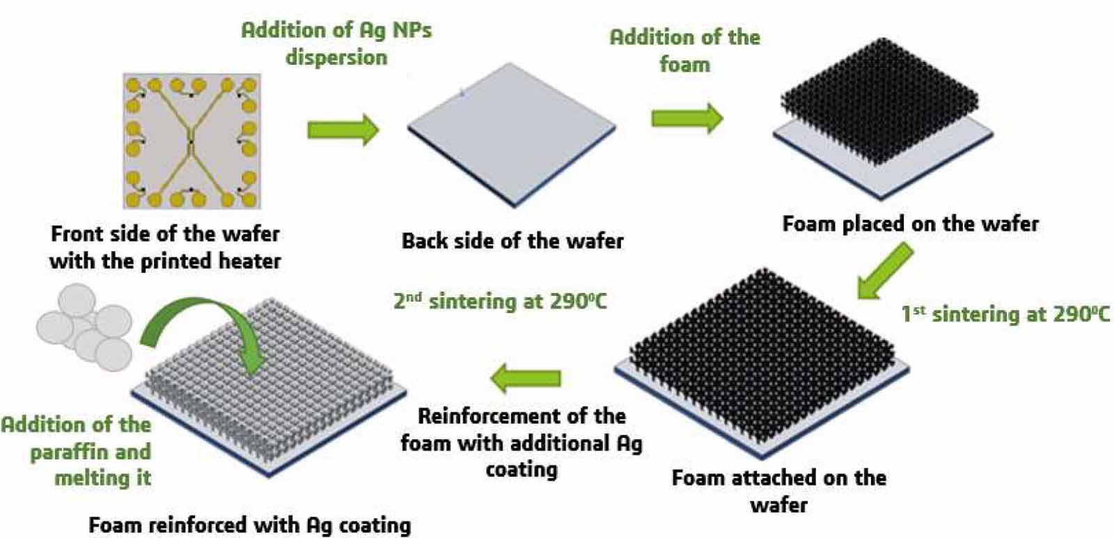
Graphene foam was grown using CVD method. The graphene growth is initiated through the introduction of ethanol gas in a tube furnace where the nickel foam was heated up to 1000 °C. More details of the growth process and characterisation can be found in previously published articles from the graphene foam source (NTU, Singapore) [36–38]. The graphene foam obtained was with pore size between 100–200 μm, 99.6% (i.e. including primary and secondary microporosity), 5 mg cm−3 density and 1.7 mm height. Nickel foam with a bulk density of 0.95 g cm−3 and 95% porosity and Ag NPs with a diameter less than 50 nm were purchased from Sigma Aldrich AB, Sweden. The nanoparticles were dispersed in ethylene glycol which acts as a stabilisation phase. Ethylene glycol was removed during the process of the sintering at temperatures higher than 150 °C. To attach the foam on the heater, a thin layer of Ag nanoparticles was disposed on the back surface of a heater with a thickness of 500 µm. A 20 · 20 mm2 piece of foam was cut and positioned on the back of the heater before being sintered at 290 °C in a vacuum oven. Additional 0.04 g of Ag NPs dispersion was added into the graphene foam by dropping the dispersion on top of the foam in an extra step and sintered as a coating under the same conditions. Finally, different amounts of paraffin were added to investigate the overall thermal performances of the high porosity foam with different weights of paraffin including 0.10 g, 0.15 g, 0.20 g,0.25 g, 0.30 g, 0.35 g and 0.40 g. The paraffin was introduced into the foam porosity by depositing an increment 0.05 g of paraffin gradually on top of the foam and raising the temperature of the heater above the melting temperature of the PCM. The liquid phase infiltrates the foam porosity in result of the gravity and capillary effect. Figure 1 summarises the sample preparations steps.

Figure 1. Schematic representation of the sample preparation. The foam is first attached on the back side of the heater using Ag NPs sintering. Then, additional Ag NPs dispersion was applied and sintered as a coating.
Download figure:
Standard image High-resolution imageThe microstructure of the graphene nickel foam, graphene foam and silver-coated graphene foam was observed with scanning electron microscopy (SEM—Zeiss Supra 55—EDX). The thermal conductivity of the graphene foam and the silver-coated graphene foam were measured using the self-heating method by the dependence resistance on temperature (DRT) [39]. Freestanding samples of 20 · 5 mm2 of graphene foam with and without silver coating were glued between two copper blocks that act as heat sinks for the measurements. To evaluate the graphene foam's heat spreading properties, a resistance thermometer was fabricated through microfabrication. The concept behind a resistance thermometer is to use a temperature-sensitive material and measure the temperature by monitoring the change in the electrical resistance [40]. The resistance thermometer chip consists of a 390 · 400 µm2 hot spot made of a 45 nm of gold on top of 5 nm thick layer of titanium. The heater was attached to a T-type thermocouple at the centre of the heater (i.e. gold pattern side) to track the evolution of the temperature using an Agilent (NI 9211 DAQ) data acquisition with LabView software and a 1 Hz frequency. The sensor was attached to the heater using a rubber gum in order to ensure contact and avoid convection on the heating side. The different power levels applied were 0.24 W, 0.35 W, 0.64 W to 1 W.
3. Results and discussion
The microstructures of the different samples are shown in figure 2. The addition of the coating is clearly distinguished with a bright contrast in the middle of the struts in result of the concave cross-section of the foam (cf figure 2(c)). The internal secondary microchannels along the foam struts are shown in figure 2(d) on a broken node before the addition of the metallic coating. It is understood that the hollow structure is formed because of the etching of the nickel phase that served as a growth substrate. The infiltrated Ag NPs in figure 2(e) can be observed covering part of the foam wall with a layer of less than 500 nm around the struts. After the addition of the solver coating, the fraction of the porosity slightly decreased and reached 99.44%. After sintering at 290 °C, the NPs densified and better contact was achieved along the metallic phase (cf figure 2(f)).

Figure 2. SEM observations of (a) nickel foam, (b) graphene foam, (c) graphene foam coated with Ag NPs, (d) internal secondary microchannels within showed on broken foam node, (e) Ag NPs deposited on graphene sheets, (f) sintered Ag NPs at 290 °C.
Download figure:
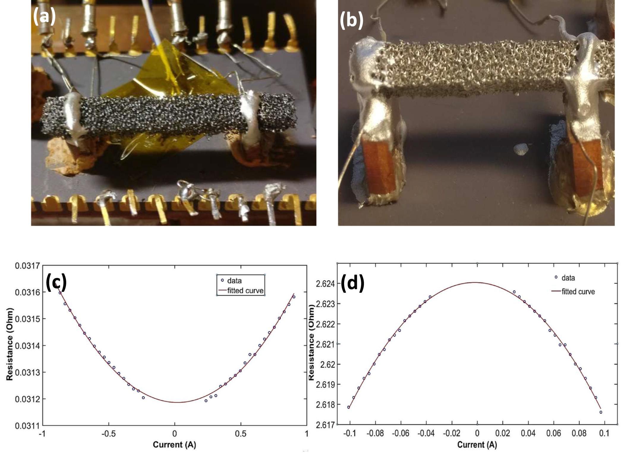
Standard image High-resolution imageThe thermal conductivity of graphene foam and graphene foam/silver (GF/Ag) were measured with DRT Joule heating with a standard error of less than 10%. The results are shown in figure 3. The thermal conductivity of the samples was calculated through the measurement of the resistance variation of the foams as a function of the Idc current as a direct result of the temperature rise [41]. The calculated effective thermal conductivities of the graphene foam and the graphene foam with silver coating corresponded to 1.3 W m−1 K−1 and 2 W m−1 K−1 with a resistivity of 1 · 10−3 Ωm and ρ = 1.35 · 10−5 Ωm, respectively.

Figure 3. DRT setup and results of the measurement. (a) photograph of the graphene foam suspended between two copper blocks; (b)photograph of graphene foam coated with silver and suspended between two copper blocks; (c) resistance measurement at different current of the graphene foam; (d) resistance measurement at different current of the graphene foam coated with silver.
Download figure:
Standard image High-resolution imageThe values of electrical resistivities in the case of graphene foam and GF/Ag foam were three order of magnitude and one order of magnitude lower than reported results on the electrical resistivity of sintered silver nanoparticles, respectively [42, 43]. It is worth noting that the GF/Ag electrical behaviour changed with the addition of the sintered metallic particles. Before the addition of the silver coating, the foam exhibited a typical graphene behaviour with a nonlinear inverse proportional resistance increase with the current due to the negative temperature coefficient of resistance of graphene (cf figure 3(c)) [44]. With a positive temperature coefficient of resistance, the presence of silver switched the mode of conduction to pure metallic behaviour with a proportional increase in the resistance with temperature as an ohmic linear behaviour (cf figure 3(d)). It is assumed that in the presence of the metallic phase, the valance electrons present in the conduction band contribute more in the electrical conduction with a weak interaction between silver and graphene (i.e. low carbon-carbon atomic distance 1.284 Å that indicate high atomic distance between carbon-silver [45]). The graphene foam is assumed to act as a scaffold for the metallic structure, and that the measured electrical resistivity is a result of the composite response where the graphene foam electrical property plays a negative role to degrade the properties the electrical response of the sintered silver nanoparticles.
The values of thermal conductivities measured are in accordance with previously reported values of graphene foam effective thermal conductivities between 0.26 to 1.70 W m−1 K−1 [30]. Using the parallel composite model and with a solid volume fraction of 0.4 vol.%, the thermal conductivity of the solid graphene foam was estimated to be 319 W m−1 K−1. While such thermal conductivity is as high as the gold thermal conductivity and higher than most metallic materials. The addition of the silver coating resulted in the improvement of the thermal conductivity. In fact, with a solid fraction of 0.56 vol.%, the composite effective thermal conductivity reached a value of 2 W m−1 K−1 that corresponds to a solid thermal conductivity of 352 W m−1 K−1. Such increase in the thermal conductivity of the foam with the silver coating is assumed to be due to the high thermal conductivity of silver and the increase in the carbon-based and metallic fraction in detriment of the porosity. In fact, the porosity level after the addition of the metallic coating decreased to 99.44% and was reported to affects inverse proportionally the effective thermal conductivity of the high porosity GF/Ag-PCM system [13, 22].
Figure 4 shows the temperature dependence of the hot spot at four different power levels (0.24 W, 0.35 W, 0.64 W and 1 W). As a reference, the temperature profiles at the centre of the heaters were compared to the case of the absence of a heat sink at the back of the heater.

Figure 4. Temperature rise at different power level in the case of (a) no heat sink and (b) three heat sinks (i.e. graphene foam (GF), nickel foam (Ni-F) and graphene foam coated with Ag (GF/Ag)). (c) SEM observation of the contact between the graphene struts and the substrate with multiple struts connected and (d) single column in contact with the substrate.
Download figure:
Standard image High-resolution imageAt 0.24 W, the junction temperature of the heater reached 34 °C and increased to 38 °C at 0.36 W before stabilising at 51 °C and 68 °C in the cases of 0.64 W and 1 W respectively. When nickel foam was added as the heat sink, it was found that the sintered pure nickel foam exhibited an even worse thermal cooling than the heater without a heat sink. While the temperatures at low powers (i.e. 0.24 W and 0.35 W) were comparable to the temperatures of only heater, those of 0.64 W and 1 W were 4 degrees and 6 degrees higher, respectively. In the case of the graphene foam as the heat sink, the junction temperatures at the four power levels decreased by a 1.5, 2, 6 and 12 degrees with the increased power levels. Finally, with the addition of the silver coating, the temperature achieved in the case of the four power levels reached 4 °C, 4.5 °C, 7.5 °C and 13 °C. The additional improvement in the thermal behaviour of the porous composite can be explained by the presence of a high thermal conductivity metallic phase and the increase in the density of the solid phase in the detriment of the porosity.
The SEM observations of the contact interface between the graphene foam on the substrate shown in figure 4(c) and (d) indicate good contact between the foam and the substrate. The structs were observed to open at the interface and maximise the contact between the foam and its substrate. In contrast, the rigid nickel foam was found to achieve poor contact small contact area that hinders high heat conduction away from the heater. When the metallic silver phase was added to the pre-attached foam as coating, the solid density increased without affecting the quality of the contact while the solid phase and its thermal conductivity were enhanced.
In the next step, the organic phase change materials were infiltrated into the 3D porous foam. Different amounts of paraffin were added, and the evolution of the temperature was recorded. It is worth mentioning that due to the porous nature of the foam, the infiltrated PCM was absorbed easily and contained in the 3D structure. The foam acted as a container with no leaking for the paraffin, and no additional setup was required to hold the organic solid and liquid within it at vertical and horizontal positions. The maximum amount of PCM contained with the experimented dimensions was 0.4 g. Above this weight, the melted PCM at high temperature was dripping.
The results of the thermal behaviour of the graphene foam coated with sintered silver and infiltrated with paraffin are shown in figure 5. At the lowest power level, (i.e. 0.24 W) the junction temperatures of the chip with different paraffin loads were below 35 °C. The maximum temperature achieved did not reach the melting point of the organic phase, and a minimal effect was observed on the transient heating (cf figure 5(a)). The difference in the values of the temperatures comparing the three samples is due to the enhancement in the heat flux through the solid phase. However, at 0.36 W in figure 5(b), the effect of the presence of the organic PCM was observed. The power level was high enough to melt the PCM and induces the solid phase changed into a liquid phase. Different temperature delays were observed depending on the PCM load.

Figure 5. Transient temperature of graphene foam coated with Ag with different PCM load at: (a) 0.24 W, (b) 0.35 W, (c) 0.64 W and (d) 1 W. (e) Measurment comparison of graphene foam coated with Ag at horizontal and vertical orientations. (f) Summary of the junction temperatures (blue) and time to reach the maximum temperature (green/red) at different power levels and PCM loads.
Download figure:
Standard image High-resolution imageIn the case of silver-coated graphene foam, the temperatures reached a maximum of 33 °C within 107 s. When the paraffin was added, a delay in the equilibrium temperature was observed. The higher the amount of PCM added, the higher the amount of energy absorbed to melt the solid organic phase and the longer it takes to achieve a stable temperature. The same trends were observed at higher power levels of 0.64 W and 1 W shown in figures 5(c) and (d). The temperatures of the heater raised above the melting of the PCM and a delay was observed in reaching the maximum temperatures. With higher amounts of PCM within the foam, the junction temperatures at the respective power levels are decreased.
Figure 5(f) summarises the junction temperatures and the time delay to reach them depending on the power level and the amount of PCM. The presence of the organic phase reduces the heat transfer via convection before melting and increases the conduction within the PCM. The thermal conductivity of the paraffin is known to be ten times higher than air and the addition of the different masses of paraffin resulted in a proportional improvement of the thermal conductivity. The presence of graphene foam achieved an improvement of the effective thermal conductivity of the composite and the silver coating increased further its effective thermal conductivity by increasing the thickness and the density of the matrix. As the conduction mode in such structure is considered dominating the heat transfer, the thickening of the matrix dimension is assumed to result in an increase in the heat transfer efficiency and in shortening the melting time of the PCM. With the small modification in the matrix density after the addition of the coating, the thermal energy storage capabilities are were not sacrificed.
4. Model of the airflow within the secondary microchannels and its contribution in the heat exchange
The experimental results of this work can be described by the heat conduction in solid and fluid flow through a high porosity medium when the substrate is subjected to a constant heat flux. The heat transfer and fluid flow were modelled using the finite element method (FEM) software COMSOL Multiphysics v5.4 to compute the thermal behaviour of the graphene foam and the convective airflow within it. In the study, the contribution from convection was considered while the radiative heat transfer and the temperature dependence of other properties were neglected. The structure of the graphene foam is complex, and it is delicate to reproduce to the last detail the nuances of the 3D structure. However, it is valid to simplify the representation to a model of interconnected fibres that allows to a fair degree to compute the properties and behaviour of the foam [46]. As the work focuses on the steady state of an incompressible fluid flow where the compressibility and viscosity effects are considerably smaller than the Bernoulli effect, a cubic unit cell with cross ligaments for the 2D cross-section of the representation of the foam microstructure for simplicity was adopted. The goal in this approach is to help understand the behaviour of the system qualitatively and identify the role of the additional microporosity within the foam. The temperature of the solid phase was assumed to be constant in the vertical direction as a result of the high thermal conductivity of the graphene foam (cf figure 6). A velocity of 0.1 m s−1 was forced in order to take into consideration the experiment conditions [47, 48].

Figure 6. (a) 3D model of the one single column part of the foam with five nodes, (b) 2D representation of the single column foam with lines profiles and local levels indicated for the studied parameters.
Download figure:
Standard image High-resolution imageThe CFD Module in COMSOL was used to study the fluid flow within such a structure. The model was developed through a 3D steady-state heat transfer of one column. Due to the high thermal conductivity of the solid phase of the graphene foam, we assumed the temperature along the vertical axis to be constant and fixed at 55 °C. As many studies have shed light on the airflow within the primary foam porosities in earlier studies, e.g. [49, 50], we focused in this study on identifying the role of the fluid flow within the secondary channels and its effect on the heat exchange process.
The velocity magnitudes were extracted from the simulation results and are shown in figure 7(a), while the pressure evolution and the convective heat flux magnitudes are shown in figures 7(b) and (c), respectively. To emphasis the difference in the profiles of the reported parameters, partitions of the volumes and insets images of the top part of the foam with limited scale values are presented. Comparatively to the flow within the primary microchannels, the air velocity in the secondary microchannels is more decelerated and reaches a value of o.005 m s−1 at 1.5 mm. The same value of velocity is reached within the primary microchannels at the height of 1.2 mm. Both profiles follow the deceleration trend with a higher air velocity in the primary microchannels. The pressure profile shows a pressure build-up at the entrance of the secondary channel that results in a lower airflow within the microchannel. The convective heat flux being proportional to the velocity of the fluid, it shows the same trend as the air velocity within the two microchannels (i.e. primary and secondary). The maximum convective flux is found at the top of the foam where the airflow has the maximum velocities of 6340 W m−2. In the case of the primary microchannels (cf figure 7(d), line profile 2), the convective heat flux slowly decreases as the airflow is slowed down. For the secondary microchannels (cf figure 7(d), line profile 1), the convective heat flux decreases gradually after each node along the vertical struts. However, the convective flux in the latter case is still comparable to the convective flux within the primary microchannels and contributes to the overall heat exchange. Table 1 summarises the values of the ratio between the airflow within the primary and the secondary microchannels at five different levels (cf figure 6). Comparatively to heat flux in high porosity foams such in the case of metallic foam, it appears that the connective heat flux plays a minor role in the cooling process as most of the cooling is achieved through the conduction mode.

Figure 7. 3D profile showing the (a) velocity magnitude with an inset of the top of the foam with a maximum scale limited to 10 · 10–4 m s−1, (b) pressure evolution along the vertical column with an inset of the top of the foam and a maximum scale limited to 0.1 Pa, (c) convective heat flux along the column with an inset of the top of the foam and a maximum scale limited to 5 · 102 W m−2 (d) profiles of the air flow velocity and convective heat flux magnitudes along the primary and secondary microchannels in the vertical direction.
Download figure:
Standard image High-resolution image
Table 1. Ratio values of velocity, pressure variation and convective heat flux magnitudes at five points along the foam column between the flow in the primary and secondary microchannels.
| Velocity magnitude ratio | Pressure variation ratio | Convective heat flux ratio | |
|---|---|---|---|
| Level 1 | 15.41 | 0.08 | 15.41 |
| Level 2 | 10.61 | 0.20 | 10.61 |
| Level 3 | 8.09 | 0.14 | 8.09 |
| Level 4 | 6.50 | 0.12 | 6.50 |
| Level 5 | 5.09 | 0.09 | 5.09 |
In the steady-state regime, the fluid flow within the primary microchannels follows the model of pipe flow within tubular walls where the diameter of the tube is smaller than its length in a conduit. The fluid entering the vertical column experience a pressure drop along the internal walls due to stress at the wall determined by the friction factor and results in a non-uniform fluid velocity across the strut section. Considering the lamellar regime, the fluid movement can be represented with parallel streamlines along the vertical parts of the foam column. At the level of the nodes, the fluid flow experiences an additional pressure drop due to the opening in the horizontal direction that results in a further decrease of its velocity. In contrast, the fluid flow in the primary channels follows the model of fluid flow in open conduits as a result of the open cell nature of the foam. The fluid flow in the primary microchannels experiences a slowdown in the velocity as a result of the interaction with the external walls and the stress built by the air layer at the contact of the wall. The heat flux being directly proportional to the velocity of the fluid, it is seen to follow the same behaviour in the secondary and the primary micros porosity, respectively.
5. Conclusion
This work was undertaken to investigate the effect of the use of graphene foam as a heat sink in combination with phase change materials. The graphene foam effective thermal conductivity was measured using DRT joule heating and further enhanced through the addition of a silver coating by sintering silver nanoparticles to reach a 54% increase in its effective thermal conductivity. Even though the thermal conductivity of the composite was found lower than that of pure copper, it is assumed that such structure can still be a good alternative for application in electronics where copper is not recommended. Further improvement of the thermal conductivity of the foam can be investigated by decreasing the graphene thickness in term of number of layers and proceeding to heat treatments to improve the structural properties of the foam and enhance the thermal transport capabilities. Also, the variation within the micrometre scale in other high porosity graphitic structures can be implemented in order to improve the effective thermal conductivity of the GF/Ag-PCM composite by increasing the solid matrix density.
The temperature rise of a heater underneath the porous foam was monitored under different power levels. The use of NPs sintering allowed to achieve a good quality sintering at relatively low temperatures. The flexibility of the graphene foam offered the possibility to connect a maximum number of vertical struts without the use of pressure. The temperature of the heater in the case of the graphene foam was found to be lower than in the case of the nickel foam as a result of the high thermal conductivity of the graphene foam and better contact with the substrate. The presence of Ag coating helped improve the thermal properties of the foam and lowered further the junction temperature of the heater. The impregnation of the organic PCM resulted in the slowdown of the temperature-rise considerably while showing a small effect on the maximum temperature.
A CFD model was developed and showed that the additional secondary microchannels within the foam contribute to the heat transfer. A pressure drop was observed along the horizontal axis of the foam within the internal secondary microchannels as well as a decrease in the heat transfer efficiency. However, the decrease in the convective heat exchange was found comparable to the value of the convective heat flux within the primary microchannels of the foam. Even though the conduction mode is dominating the heat transfer process in such systems, we found that the secondary microchannels in the case of graphene foam-based approach can have a positive and non-negligible contribution in the heat transfer process. This gives a chance to potential use of this system in advanced heat transfer strategies combining high conductivity material, high latent energy, and high convective heat flux approach.
Acknowledgments
We acknowledge the financial support from the Swedish Board for Strategic Research (SSF) with the contract No: GMT14-0045 and SE13-0061, from the Swedish Board for Innovation (Vinnova) under the SiO Grafen program, from Formas with the contract No: FR-2017/0009 and from the Swedish National Science Foundation with the contract No: 621-2007-4660 as well as from the Production Area of Advance at Chalmers University of Technology, Sweden. The authors would like to acknowledge the help and assistance from Dr. Gustav Mårtenssen regarding the study of the fluid flow model. The authors also would like to acknowledge Dr. Teo Hang Tong Edwin and Dr. Tsang Siu Hon from the Nanyang Technological University (NTU) for providing the 3D graphene foam. This work was performed in part at Myfab Chalmers facility.